2003 SSANGYONG MUSSO clutch
[x] Cancel search: clutchPage 1133 of 1574
5D2-44 TRANSFER CASE (TOD)
9. Remove the bolts that retain the front case to therear case. Make sure that the front case is facing downward so that the rear cover is facing upwards. Pry on the bosses and separate the front case fromthe rear case. Remove all traces of gasket sealantfrom the mating surfaces of the front case and rearcase.
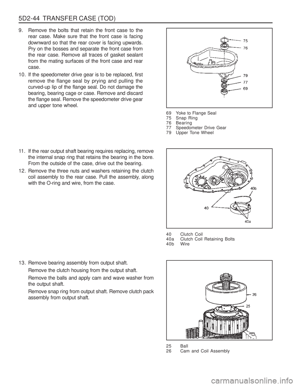
10. If the speedometer drive gear is to be replaced, first remove the flange seal by prying and pulling thecurved-up lip of the flange seal. Do not damage thebearing, bearing cage or case. Remove and discardthe flange seal. Remove the speedometer drive gearand upper tone wheel.
69 Yoke to Flange Seal
75 Snap Ring
76 Bearing
77 Speedometer Drive Gear
79 Upper Tone Wheel
40 Clutch Coil
40a Clutch Coil Retaining Bolts
40b Wire
11. If the rear output shaft bearing requires replacing, removethe internal snap ring that retains the bearing in the bore. From the outside of the case, drive out the bearing.
12. Remove the three nuts and washers retaining the clutch coil assembly to the rear case. Pull the assembly, alongwith the O-ring and wire, from the case.
13. Remove bearing assembly from output shaft. Remove the clutch housing from the output shaft. Remove the balls and apply cam and wave washer from the output shaft. Remove snap ring from output shaft. Remove clutch pack assembly from output shaft.
25 Ball
26 Cam and Coil Assembly
Page 1134 of 1574
TRANSFER CASE (TOD) 5D2-45
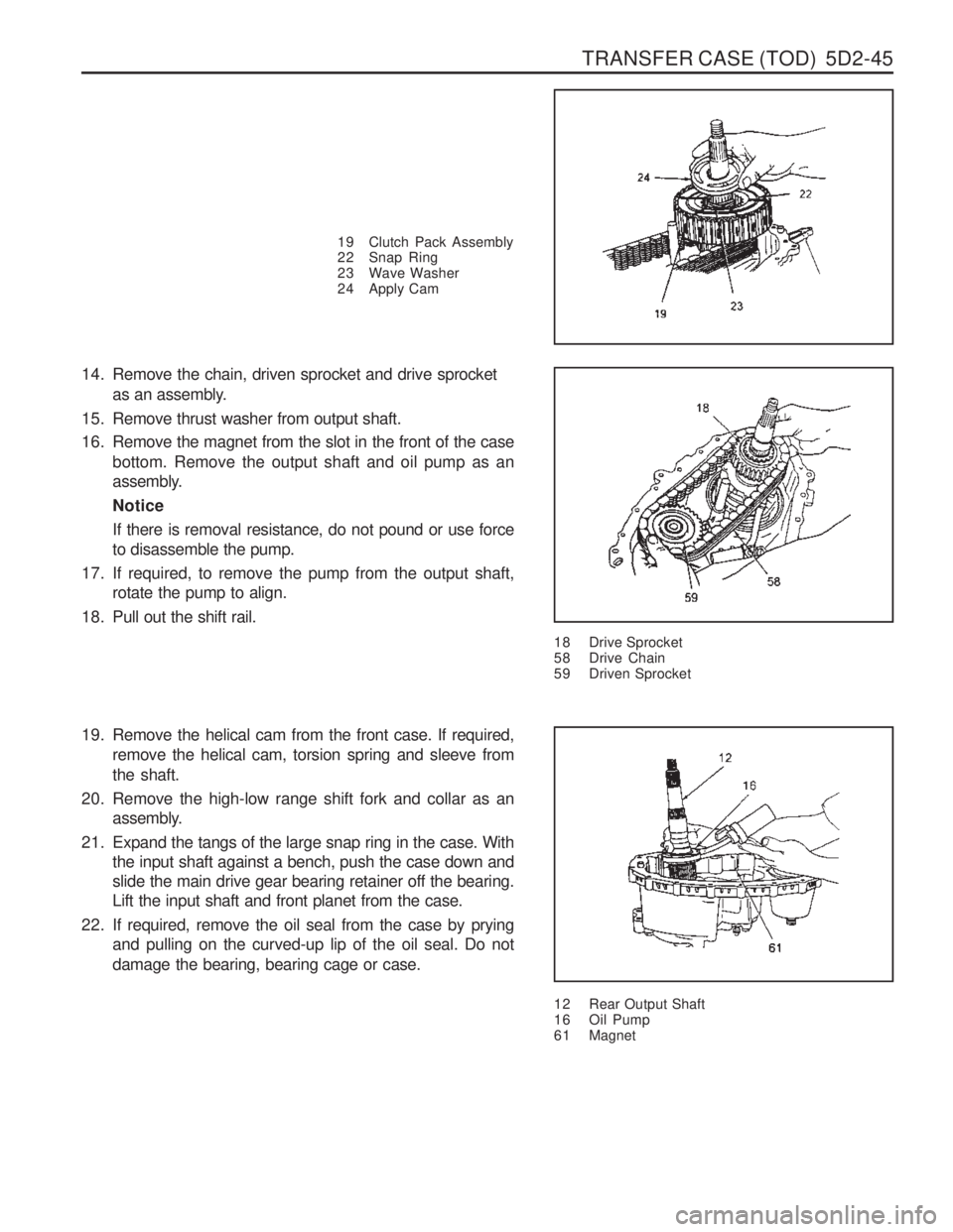
19 Clutch Pack Assembly
22 Snap Ring
23 Wave Washer
24 Apply Cam
14. Remove the chain, driven sprocket and drive sprocketas an assembly.
15. Remove thrust washer from output shaft.
16. Remove the magnet from the slot in the front of the case bottom. Remove the output shaft and oil pump as an
assembly. NoticeIf there is removal resistance, do not pound or use force to disassemble the pump.
17. If required, to remove the pump from the output shaft, rotate the pump to align.
18. Pull out the shift rail.
18 Drive Sprocket
58 Drive Chain
59 Driven Sprocket
12 Rear Output Shaft
16 Oil Pump
6 1 Magnet
19. Remove the helical cam from the front case. If required,
remove the helical cam, torsion spring and sleeve from the shaft.
20. Remove the high-low range shift fork and collar as an assembly.
21. Expand the tangs of the large snap ring in the case. With the input shaft against a bench, push the case down and slide the main drive gear bearing retainer off the bearing.Lift the input shaft and front planet from the case.
22. If required, remove the oil seal from the case by prying and pulling on the curved-up lip of the oil seal. Do not damage the bearing, bearing cage or case.
Page 1138 of 1574
TRANSFER CASE (TOD) 5D2-49
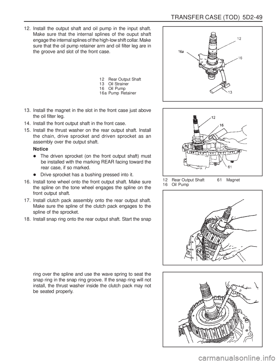
12. Install the output shaft and oil pump in the input shaft.Make sure that the internal splines of the ouput shaft
engage the internal splines of the high-low shift collar. Make sure that the oil pump retainer arm and oil filter leg are inthe groove and slot of the front case.
13. Install the magnet in the slot in the front case just above the oil filter leg.
14. Install the front output shaft in the front case.
15. Install the thrust washer on the rear output shaft. Install the chain, drive sprocket and driven sprocket as an assembly over the output shaft. Notice
�The driven sprocket (on the front output shaft) must
be installed with the marking REAR facing toward the rear case, if so marked.
� Drive sprocket has a bushing pressed into it.
16. Install tone wheel onto the front output shaft. Make sure the spline on the tone wheel engages the spline on thefront output shaft.
17. Install clutch pack assembly onto the rear output shaft. Make sure the spline of the clutch pack engages to the spline of the sprocket.
18. Install snap ring onto the rear output shaft. Start the snap
ring over the spline and use the wave spring to seat the snap ring in the snap ring groove. If the snap ring will notinstall, the thrust washer inside the clutch pack may not
be seated properly. 1 2 Rear Output Shaft
1 6 Oil Pump
6 1 Magnet
1 2 Rear Output Shaft
1 3 Oil Strainer
1 6 Oil Pump
1 6 a Pump Retainer
Page 1139 of 1574
5D2-50 TRANSFER CASE (TOD)
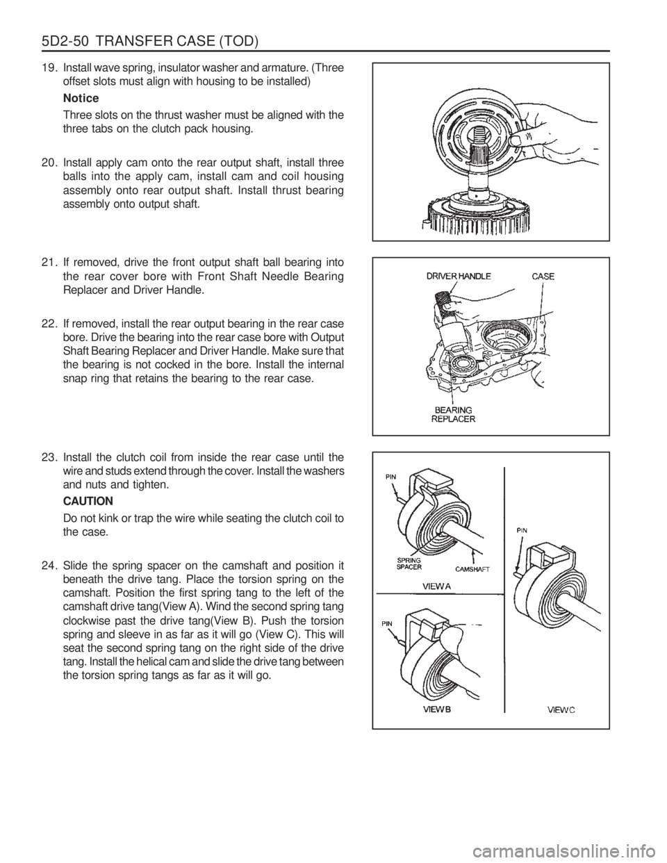
19. Install wave spring, insulator washer and armature. (Threeoffset slots must align with housing to be installed) NoticeThree slots on the thrust washer must be aligned with the three tabs on the clutch pack housing.
20. Install apply cam onto the rear output shaft, install three balls into the apply cam, install cam and coil housing assembly onto rear output shaft. Install thrust bearing assembly onto output shaft.
21. If removed, drive the front output shaft ball bearing into
the rear cover bore with Front Shaft Needle Bearing Replacer and Driver Handle.
22. If removed, install the rear output bearing in the rear case bore. Drive the bearing into the rear case bore with OutputShaft Bearing Replacer and Driver Handle. Make sure thatthe bearing is not cocked in the bore. Install the internalsnap ring that retains the bearing to the rear case.
23. Install the clutch coil from inside the rear case until the wire and studs extend through the cover. Install the washersand nuts and tighten. CAUTIONDo not kink or trap the wire while seating the clutch coil to the case.
24. Slide the spring spacer on the camshaft and position it beneath the drive tang. Place the torsion spring on thecamshaft. Position the first spring tang to the left of thecamshaft drive tang(View A). Wind the second spring tang clockwise past the drive tang(View B). Push the torsion spring and sleeve in as far as it will go (View C). This willseat the second spring tang on the right side of the drivetang. Install the helical cam and slide the drive tang betweenthe torsion spring tangs as far as it will go.
Page 1141 of 1574
5D2-52 TRANSFER CASE (TOD)
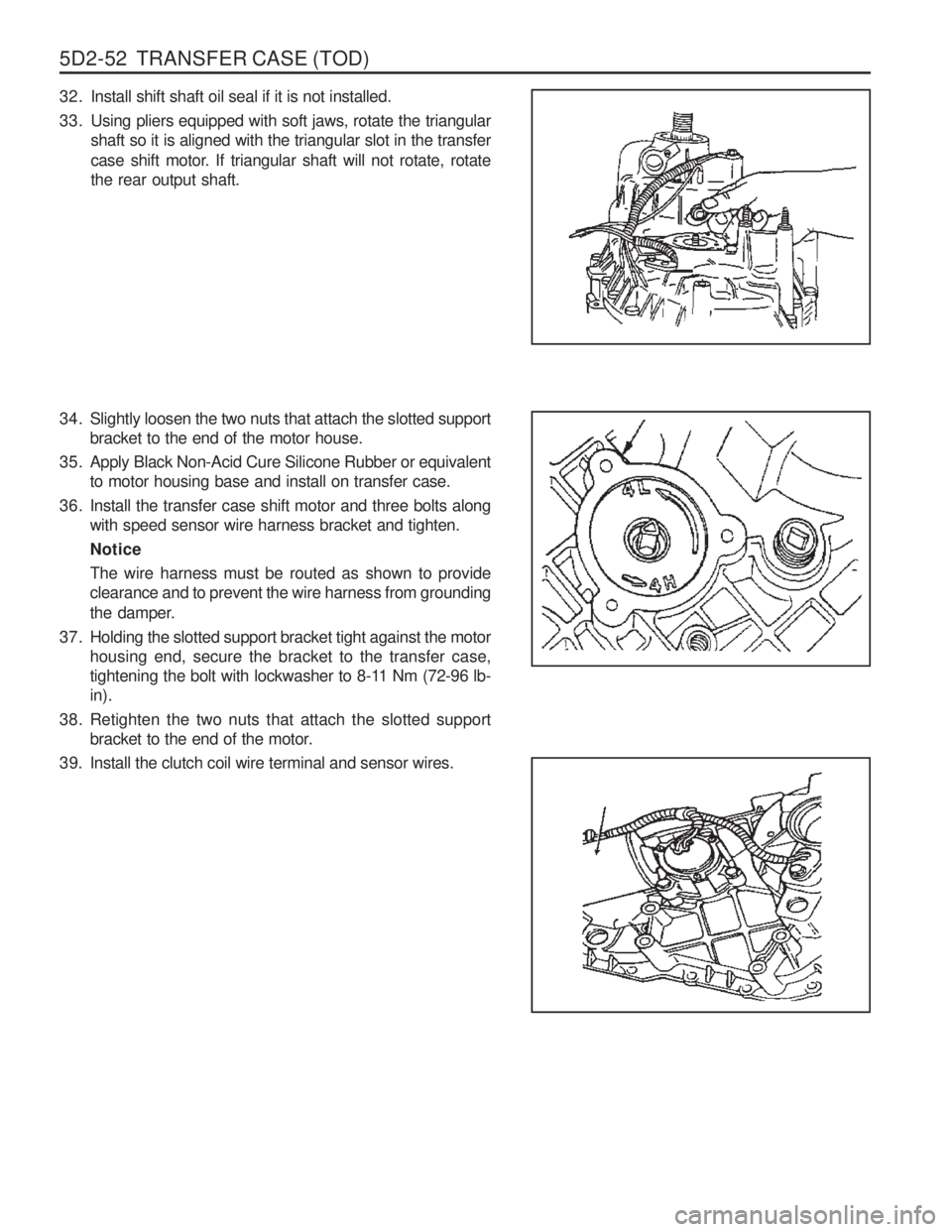
32. Install shift shaft oil seal if it is not installed.
33. Using pliers equipped with soft jaws, rotate the triangularshaft so it is aligned with the triangular slot in the transfer
case shift motor. If triangular shaft will not rotate, rotate the rear output shaft.
34. Slightly loosen the two nuts that attach the slotted support bracket to the end of the motor house.
35. Apply Black Non-Acid Cure Silicone Rubber or equivalent to motor housing base and install on transfer case.
36. Install the transfer case shift motor and three bolts along with speed sensor wire harness bracket and tighten. NoticeThe wire harness must be routed as shown to provide clearance and to prevent the wire harness from grounding
the damper.
37. Holding the slotted support bracket tight against the motor housing end, secure the bracket to the transfer case,
tightening the bolt with lockwasher to 8-11 Nm (72-96 lb-in).
38. Retighten the two nuts that attach the slotted support bracket to the end of the motor.
39. Install the clutch coil wire terminal and sensor wires.
Page 1208 of 1574
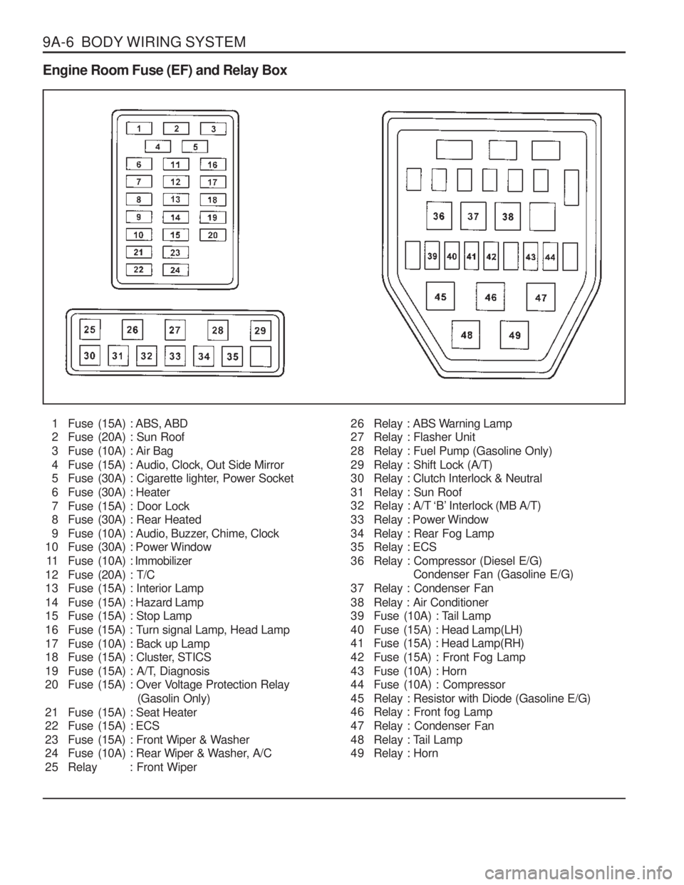
9A-6 BODY WIRING SYSTEM Engine Room Fuse (EF) and Relay Box1 Fuse (15A) : ABS, ABD
2 Fuse (20A) : Sun Roof
3 Fuse (10A) : Air Bag
4 Fuse (15A) : Audio, Clock, Out Side Mirror
5 Fuse (30A) : Cigarette lighter, Power Socket
6 Fuse (30A) : Heater
7 Fuse (15A) : Door Lock
8 Fuse (30A) : Rear Heated
9 Fuse (10A) : Audio, Buzzer, Chime, Clock
10 Fuse (30A) : Power Window
11 Fuse (10A) : Immobilizer
12 Fuse (20A) : T/C
13 Fuse (15A) : Interior Lamp
14 Fuse (15A) : Hazard Lamp
15 Fuse (15A) : Stop Lamp
16 Fuse (15A) : Turn signal Lamp, Head Lamp
17 Fuse (10A) : Back up Lamp
18 Fuse (15A) : Cluster, STICS
19 Fuse (15A) : A/T, Diagnosis
20 Fuse (15A) : Over Voltage Protection Relay (Gasolin Only)
21 Fuse (15A) : Seat Heater
22 Fuse (15A) : ECS
23 Fuse (15A) : Front Wiper & Washer
24 Fuse (10A) : Rear Wiper & Washer, A/C
25 Relay : Front Wiper 26 Relay : ABS Warning Lamp
27 Relay : Flasher Unit
28 Relay : Fuel Pump (Gasoline Only)
29 Relay : Shift Lock (A/T)
30 Relay : Clutch Interlock & Neutral
31 Relay : Sun Roof
32 Relay : A/T ‘B’ Interlock (MB A/T)
33 Relay : Power Window
34 Relay : Rear Fog Lamp
35 Relay : ECS
36 Relay : Compressor (Diesel E/G)
Condenser Fan (Gasoline E/G)
37 Relay : Condenser Fan
38 Relay : Air Conditioner
39 Fuse (10A) : Tail Lamp
40 Fuse (15A) : Head Lamp(LH)
41 Fuse (15A) : Head Lamp(RH)
42 Fuse (15A) : Front Fog Lamp
43 Fuse (10A) : Horn
44 Fuse (10A) : Compressor
45 Relay : Resistor with Diode (Gasoline E/G)
46 Relay : Front fog Lamp
47 Relay : Condenser Fan
48 Relay : Tail Lamp
49 Relay : Horn
Page 1210 of 1574
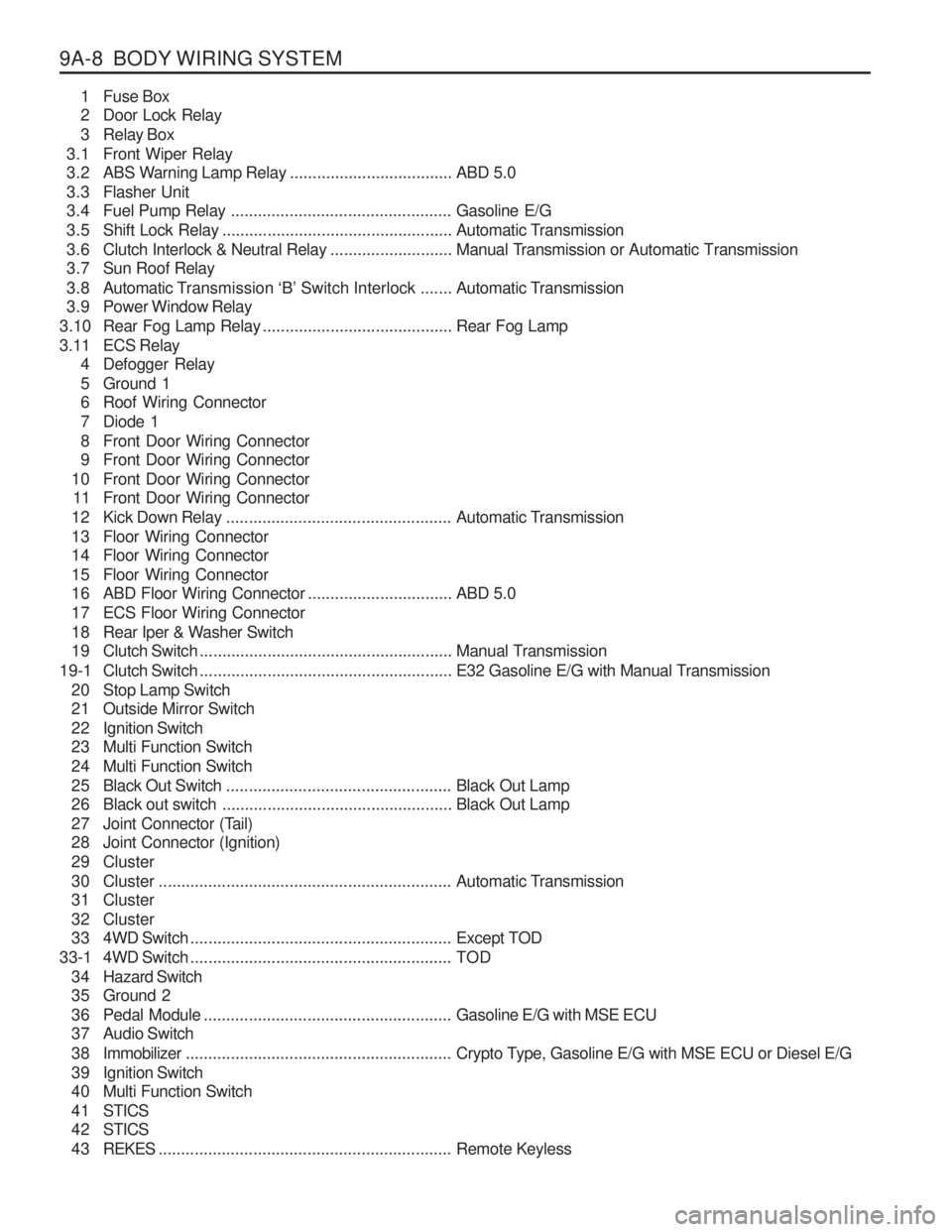
9A-8 BODY WIRING SYSTEM1 Fuse Box
2 Door Lock Relay
3 Relay Box
3.1 Front Wiper Relay
3.2 ABS Warning Lamp Relay ....................................ABD 5.0
3.3 Flasher Unit
3.4 Fuel Pump Relay ................................................. Gasoline E/G
3.5 Shift Lock Relay ................................................... Automatic Transmission
3.6 Clutch Interlock & Neutral Relay ...........................Manual Transmission or Automatic Transmission
3.7 Sun Roof Relay
3.8 Automatic T ransmission ‘B’ Switch Interlock ....... Automatic Transmission
3.9 Power Window Relay
3.10 Rear Fog Lamp Relay .......................................... Rear Fog Lamp
3.11 ECS Relay 4 Defogger Relay
5 Ground 1
6 Roof Wiring Connector
7 Diode 1
8 Front Door Wiring Connector
9 Front Door Wiring Connector
10 Front Door Wiring Connector 11 Front Door Wiring Connector
12 Kick Down Relay .................................................. Automatic Transmission
13 Floor Wiring Connector
14 Floor Wiring Connector
15 Floor Wiring Connector
16 ABD Floor Wiring Connector ................................ABD 5.0
17 ECS Floor Wiring Connector
18 Rear Iper & Washer Switch
19 Clutch Switch ........................................................ Manual Transmission
19-1 Clutch Switch ........................................................ E32 Gasoline E/G with Manual Transmission
20 Stop Lamp Switch
21 Outside Mirror Switch
22 Ignition Switch
23 Multi Function Switch
24 Multi Function Switch
25 Black Out Switch .................................................. Black Out Lamp
26 Black out switch ................................................... Black Out Lamp
27 Joint Connector (Tail)
28 Joint Connector (Ignition)
29 Cluster
30 Cluster ................................................................. Automatic Transmission
31 Cluster
32 Cluster
33 4WD Switch .......................................................... Except TOD
33-1 4WD Switch .......................................................... TOD
3 4 Hazard Switch
35 Ground 2
36 Pedal Module ....................................................... Gasoline E/G with MSE ECU
37 Audio Switch
3 8 Immobilizer ........................................................... Crypto Type, Gasoline E/G with MSE ECU or Diesel E/G
39 Ignition Switch
40 Multi Function Switch
4 1 STICS
4 2 STICS
4 3 REKES ................................................................. Remote Keyless
Page 1315 of 1574
MUSSO-SPORTS 1A-3
SUPPLEMENT
HUBER EGR
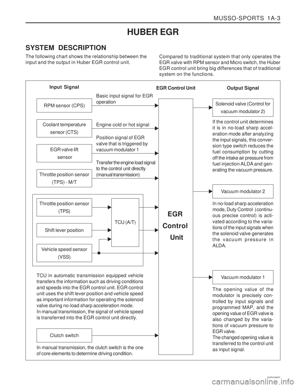
SYSTEM DESCRIPTION The following chart shows the relationship between the input and the output in Huber EGR control unit. Compared to traditional system that only operates theEGR valve with RPM sensor and Micro switch, the HuberEGR control unit bring big differences that of traditionalsystem on the functions.
Input Signal
RPM sensor (CPS)
EGR valve lift sensor
Throttle position sensor (TPS) - M/T
Shift lever position
Throttle position sensor (TPS)
Vehicle speed sensor(VSS) Basic input signal for EGR operation Engine cold or hot signal
Position signal of EGR valve that is triggered by vacuum modulator 1 Transfer the engine load signal to the control unit directly (manual transmission)
TCU (A/T)
EGR
Control
Unit
Coolant temperature sensor (CTS)
Solenoid valve (Control forvacuum modulator 2)
If the control unit determines it is in no-load sharp accel- eration mode after analyzing the input signals, this conver- sion type switch reduces the fuel consumption by cutting off the intake air pressure from
fuel injection ALDA and gen- erating the vacuum pressure. In no-load sharp acceleration
mode, Duty Control ( continu- ous precise control) is acti- vated according to the varia- tions of the input signals when the solenoid valve generates the vacuum pressure in ALDA.
Vacuum modulator 2
The opening value of the modulator is precisely con- trolled by input signals and programmed MAP, and the opening value of EGR valve is also changed by the varia- tions of vacuum pressure to EGR valve. The changed opening value is transferred to the control unit as input signal.
Vacuum modulator 1
TCU in automatic transmission equipped vehicle transfers the information such as driving conditions and speeds into the EGR control unit. EGR control unit uses the shift lever position and vehicle speed as important information for operating the solenoid valve during no-load sharp acceleration mode. In manual transmission, the signal of vehicle speed is transferred into the EGR control unit directly.
Clutch switch
In manual transmission, the clutch switch is the one of core elements to determine driving condition. Output Signal
EGR Control Unit