Page 1154 of 1574
STEERING WHEEL AND COLUMN 6E-3
Removal & Installation Procedure
1. Remove the horn pad from the steering wheel anddisconnect the connectors .
2. Place an alignment marks on the column shaft end and fixing nut and then remove the fixing nut. Installation Notice
3. Remove the steering wheel.
4. Remove the combination switch upper cover .
Tightening Torque 50 - 80 Nm
5. Release the crash pad panel. Notice Remove the hood release wire and the other switch connectors.
Page 1155 of 1574
6E-4 STEERING WHEEL AND COLUMN
6. Disconnect each connectors.
7. Remove the vacuum hose from the ignition switch(Dieselonly) .
9. Remove the lower shaft by removing the bolt of the steering column shaft. Installation Notice
Tightening Torque 9 - 14 Nm
8. Remove the combination switch assembly.
10. Remove the dash panel mounting bolts. Installation Notice
Tightening Torque 30 - 40 Nm
Page 1156 of 1574
STEERING WHEEL AND COLUMN 6E-5
Tightening Torque 30 - 40 Nm
11. Remove the steering column upper mounting bolt and pull
out steering column assembly. Installation Notice
12. Installation is reverse order of the removal.
Page 1183 of 1574

SUPPLEMENTAL RESTRAINT SYSTEM(SRS) 8B-3
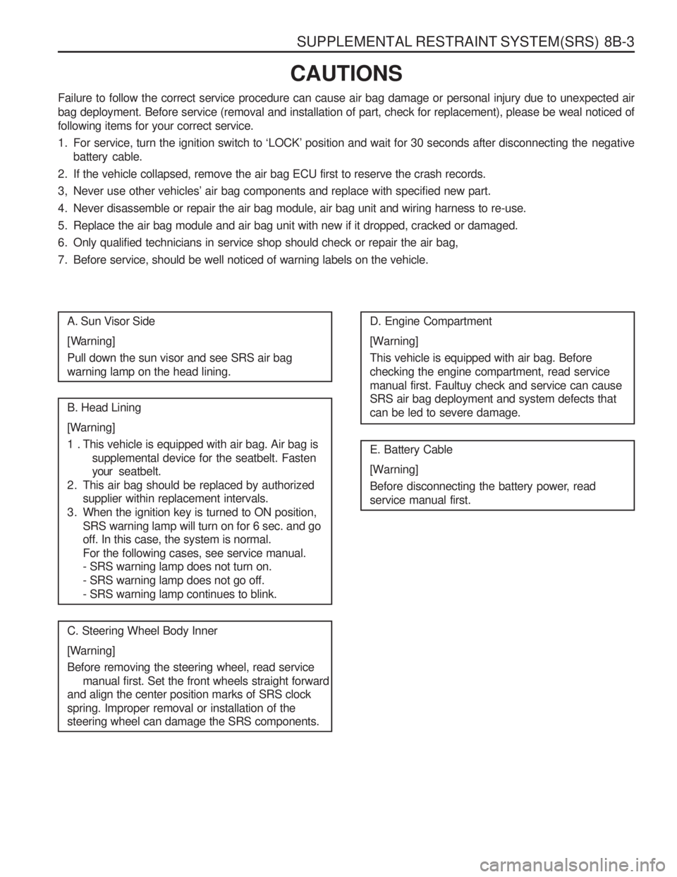
CAUTIONS
Failure to follow the correct service procedure can cause air bag damage or personal injury due to unexpected air
bag deployment. Before service (removal and installation of part, check for replacement), please be weal noticed offollowing items for your correct service.
1. For service, turn the ignition switch to ‘LOCK’ position and wait for 30 seconds after disconnecting the negative battery cable.
2. If the vehicle collapsed, remove the air bag ECU first to reserve the crash records.
3, Never use other vehicles’ air bag components and replace with specified new part.
4. Never disassemble or repair the air bag module, air bag unit and wiring harness to re-use.
5. Replace the air bag module and air bag unit with new if it dropped, cracked or damaged.
6. Only qualified technicians in service shop should check or repair the air bag,
7. Before service, should be well noticed of warning labels on the vehicle.
A. Sun Visor Side
[Warning] Pull down the sun visor and see SRS air bag warning lamp on the head lining. B. Head Lining
[Warning]
1 . This vehicle is equipped with air bag. Air bag is supplemental device for the seatbelt. Fasten your seatbelt.
2. This air bag should be replaced by authorized supplier within replacement intervals.
3. When the ignition key is turned to ON position, SRS warning lamp will turn on for 6 sec. and go off. In this case, the system is normal. For the following cases, see service manual. - SRS warning lamp does not turn on. - SRS warning lamp does not go off.- SRS warning lamp continues to blink.
C. Steering Wheel Body Inner
[Warning] Before removing the steering wheel, read service manual first. Set the front wheels straight forward
and align the center position marks of SRS clock spring. Improper removal or installation of the steering wheel can damage the SRS components. D. Engine Compartment
[Warning] This vehicle is equipped with air bag. Before checking the engine compartment, read servicemanual first. Faultuy check and service can cause SRS air bag deployment and system defects that can be led to severe damage. E. Battery Cable
[Warning]
Before disconnecting the battery power, read service manual first.
Page 1186 of 1574
8B-6 SUPPLEMENTAL RESTRAINT SYSTEM(SRS) AIR BAG MODULE
Air bag module is installed in the pad of steering wheel center and inflator is consisted of igniter, explosives, gas generating material and bag. When crashed, the air bag control unit sends current to the air bag module through squib line and this current ignites as ignition energy (6mJ) momentarily igniting explosives and bag will be inflated by nitrogen gas protecting driver at the same and then deflates.1 Air bag Module
2 Module Housing
3 Bag
4 Module Bracket
5 Retainer Ring
6 Inflator
7 Horn Switch
8 Backing Plate
Page 1198 of 1574
8B-18 SUPPLEMENTAL RESTRAINT SYSTEM(SRS)
MAINTENANCE AND REPAIR ON-VEHICLE SERVICE AIR BAG MODULE Removal & Installation Procedure
1. Remove the steering wheel rid (LH,RH) with a screwdriver.Installation Notice Each position mark (LH,RH) is stamped on the inner surface of the rids.
Tightening Torque 7 - 11 Nm
3. Disconnect the connectors and remove the air bag module.
4. Installation should follow the removal procedure in thereverse order.
2. Unscrew the bolts from both sides.
Installation Notice
Page 1200 of 1574
8B-20 SUPPLEMENTAL RESTRAINT SYSTEM(SRS) Removal & Installation Procedure preceding work : removal of steering wheel
1. Turn the ignition switch to “OFF” position and disconnectthe battery negative cable. Start the procedure after waiting over 3oseconds.
2. Unscrew 3 screws from lower cover on steering column shaft and remove the lower cover.
3. Unscrew 4 screws from clock spring and remove the clock
spring
Installation Notice
� Don’t try to repair and modify the clock spring.
� When aligning the neutral position, turn to clockwise until it stops, and turn to counter clockwise until the marks are aligned
Page 1211 of 1574

BODY WIRING SYSTEM 9A-9
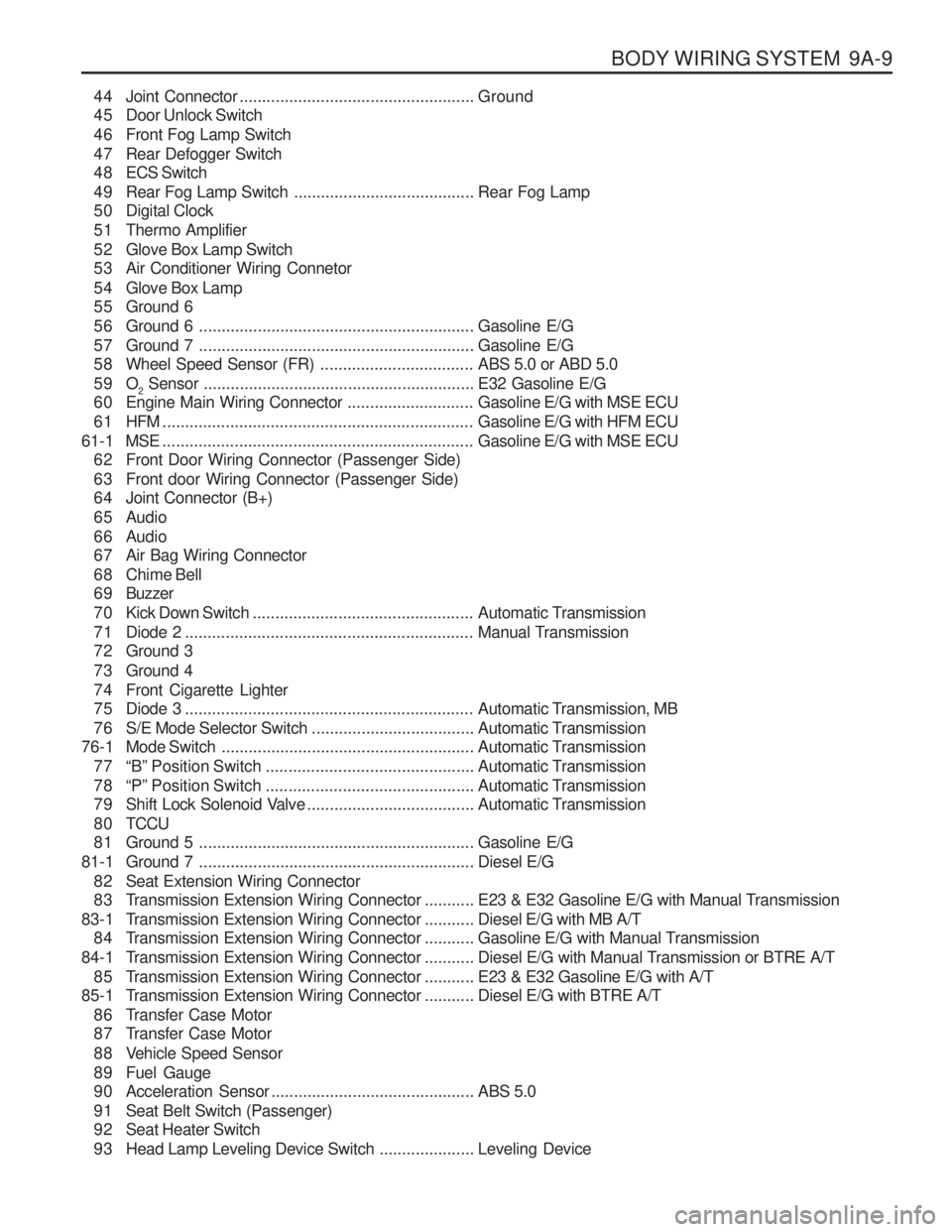
44 Joint Connector.................................................... Ground
45 Door Unlock Switch
46 Front Fog Lamp Switch
47 Rear Defogger Switch
4 8 ECS Switch
49 Rear Fog Lamp Switch ........................................Rear Fog Lamp
50 Digital Clock
51 Thermo Amplifier
52 Glove Box Lamp Switch
53 Air Conditioner Wiring Connetor
54 Glove Box Lamp
55 Ground 6
56 Ground 6 ............................................................. Gasoline E/G
57 Ground 7 ............................................................. Gasoline E/G
58 Wheel Speed Sensor (FR) ..................................ABS 5.0 or ABD 5.0
59 O 2 Sensor
............................................................ E32 Gasoline E/G
60 Engine Main Wiring Connector ............................Gasoline E/G with MSE ECU
61 HFM ..................................................................... Gasoline E/G with HFM ECU
61-1 MSE ..................................................................... Gasoline E/G with MSE ECU
62 Front Door Wiring Connector (Passenger Side)
63 Front door Wiring Connector (Passenger Side)
64 Joint Connector (B+)
65 Audio
66 Audio
67 Air Bag Wiring Connector
68 Chime Bell
6 9 Buzzer
70 Kick Down Switch ................................................. Automatic Transmission
71 Diode 2 ................................................................ Manual Transmission
72 Ground 3
73 Ground 4
74 Front Cigarette Lighter
75 Diode 3 ................................................................ Automatic Transmission, MB
76 S/E Mode Selector Switch ....................................Automatic Transmission
76-1 Mode Switch ........................................................ Automatic Transmission
77 “B” Position Switch .............................................. Automatic Transmission
78 “P” Position Switch .............................................. Automatic Transmission
79 Shift Lock Solenoid Valve .....................................Automatic Transmission
8 0 TCCU
81 Ground 5 ............................................................. Gasoline E/G
81-1 Ground 7 ............................................................. Diesel E/G
82 Seat Extension Wiring Connector
83 Transmission Extension Wiring Connector ...........E23 & E32 Gasoline E/G with Manual Transmission
83-1 T ransmission Extension Wiring Connector ...........Diesel E/G with MB A/T
84 Transmission Extension Wiring Connector ...........Gasoline E/G with Manual Transmission
84-1 T ransmission Extension Wiring Connector ...........Diesel E/G with Manual Transmission or BTRE A/T
85 Transmission Extension Wiring Connector ...........E23 & E32 Gasoline E/G with A/T
85-1 T ransmission Extension Wiring Connector ...........Diesel E/G with BTRE A/T
86 Transfer Case Motor
87 Transfer Case Motor
88 Vehicle Speed Sensor
89 Fuel Gauge
90 Acceleration Sensor ............................................. ABS 5.0
91 Seat Belt Switch (Passenger)
92 Seat Heater Switch
93 Head Lamp Leveling Device Switch .....................Leveling Device