2003 SSANGYONG MUSSO manual transmission
[x] Cancel search: manual transmissionPage 1094 of 1574
TRANSFER CASE (TOD) 5D2-5
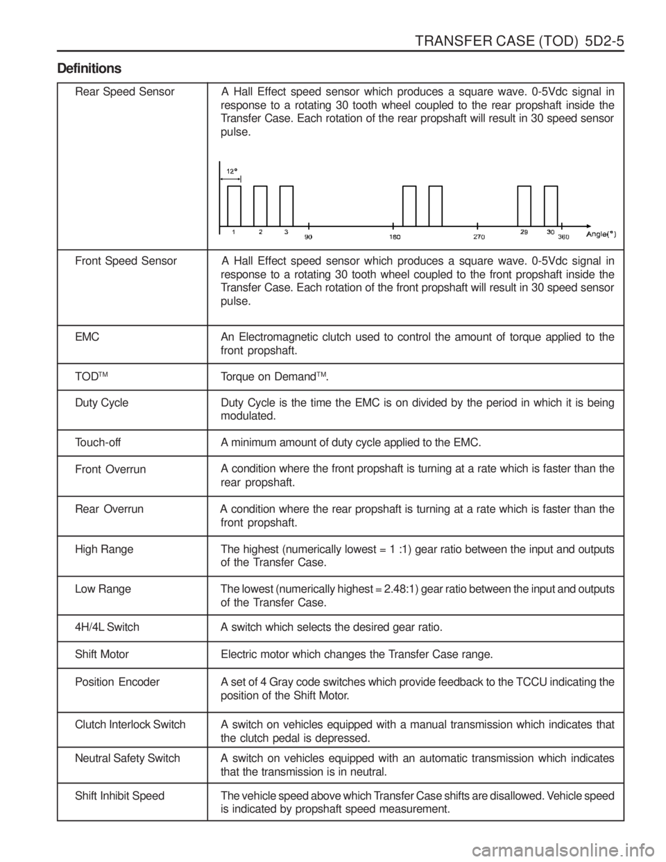
Definitions
Rear Speed Sensor A Hall Effect speed sensor which produces a square wave. 0-5Vdc signal inresponse to a rotating 30 tooth wheel coupled to the rear propshaft inside the
Transfer Case. Each rotation of the rear propshaft will result in 30 speed sensor pulse.
Front Speed Sensor A Hall Effect speed sensor which produces a square wave. 0-5Vdc signal in response to a rotating 30 tooth wheel coupled to the front propshaft inside the
Transfer Case. Each rotation of the front propshaft will result in 30 speed sensor pulse.
EMC An Electromagnetic clutch used to control the amount of torque applied to the front propshaft.
TOD TM
Torque on DemandTM
.
Duty Cycle Duty Cycle is the time the EMC is on divided by the period in which it is being modulated.
Touch-off A minimum amount of duty cycle applied to the EMC.
Front OverrunA condition where the front propshaft is turning at a rate which is faster than the rear propshaft.
Rear Overrun A condition where the rear propshaft is turning at a rate which is faster than the
front propshaft.
High Range The highest (numerically lowest = 1 :1) gear ratio between the input and outputsof the Transfer Case.
Low Range The lowest (numerically highest = 2.48:1) gear ratio between the input and outputs
of the Transfer Case.
4H/4L Switch A switch which selects the desired gear ratio.
Shift Motor Electric motor which changes the Transfer Case range.
Position Encoder A set of 4 Gray code switches which provide feedback to the TCCU indicating theposition of the Shift Motor.
Clutch Interlock Switch A switch on vehicles equipped with a manual transmission which indicates that the clutch pedal is depressed.
Neutral Safety Switch A switch on vehicles equipped with an automatic transmission which indicatesthat the transmission is in neutral.
Shift Inhibit Speed The vehicle speed above which Transfer Case shifts are disallowed. Vehicle speedis indicated by propshaft speed measurement.
Page 1108 of 1574
TRANSFER CASE (TOD) 5D2-19
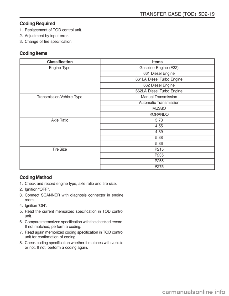
ClassificationEngine Type
Transmission/Vehicle Type Axle Ratio
Tire Size
Coding Required
1. Replacement of TOD control unit.
2. Adjustment by input error.
3. Change of tire specification.
Items
Gasoline Engine (E32) 661 Diesel Engine
661LA Diesel Turbo Engine
662 Diesel Engine
662LA Diesel Turbo Engine Manual Transmission
Automatic Transmission MUSSO
KORANDO 3.734.554.895.38 5.86
P215 P235P255P275
Coding Method
1. Check and record engine type, axle ratio and tire size.
2. Ignition “OFF ”.
3. Connect SCANNER with diagnosis connector in engine room.
4. Ignition “ON ”.
5. Read the current memorized specification in TOD control unit.
6. Compare memorized specification with the checked record. If not matched, perform a coding.
7. Read again memorized coding specification in TOD control unit for confirmation of coding.
8. Check coding specification whether it matches with vehicle or not. If not, perform a coding again.
Coding items
Page 1124 of 1574
TRANSFER CASE (TOD) 5D2-35
Removal & Installation Procedure1. Disconnect (-) cable from battery.
2. Lift on vehicle and make sure on safety. NoticeBe careful for catalytic converter due to high temperature after driving or engine running.
3. Prepare a vessel to drain transfer case and manual transmission oil.
4. Release drain plug and drain transfer case and manual transmission oil. If planar damper is installed, unscrew 4 bolts and remove
the planar damper. NoticeOil drain should be along with whole transfer case
disassembly and assembly.
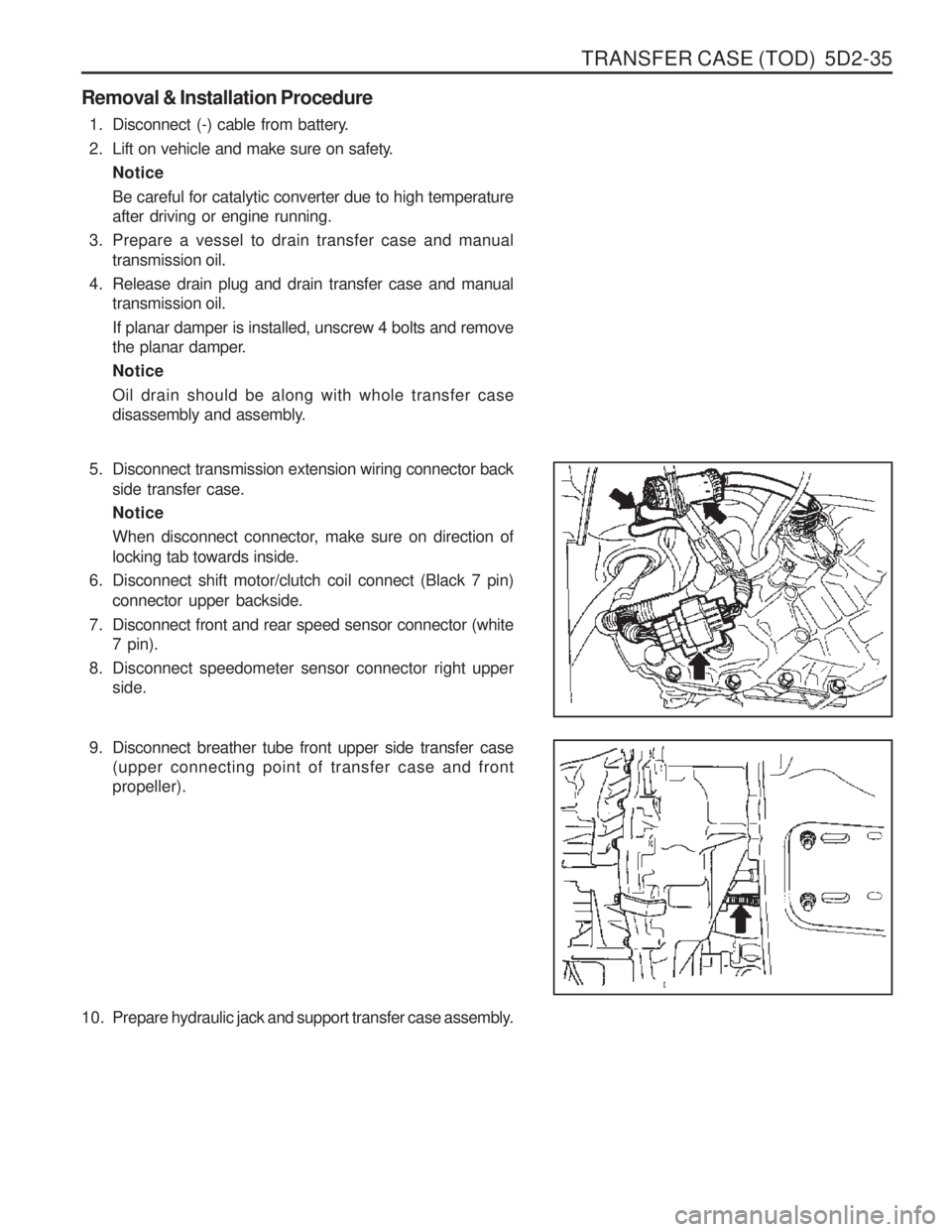
5. Disconnect transmission extension wiring connector back
side transfer case. Notice
When disconnect connector, make sure on direction of locking tab towards inside.
6. Disconnect shift motor/clutch coil connect (Black 7 pin) connector upper backside.
7. Disconnect front and rear speed sensor connector (white 7 pin).
8. Disconnect speedometer sensor connector right upper side.
9. Disconnect breather tube front upper side transfer case (upper connecting point of transfer case and front propeller).
10. Prepare hydraulic jack and support transfer case assembly.
Page 1203 of 1574
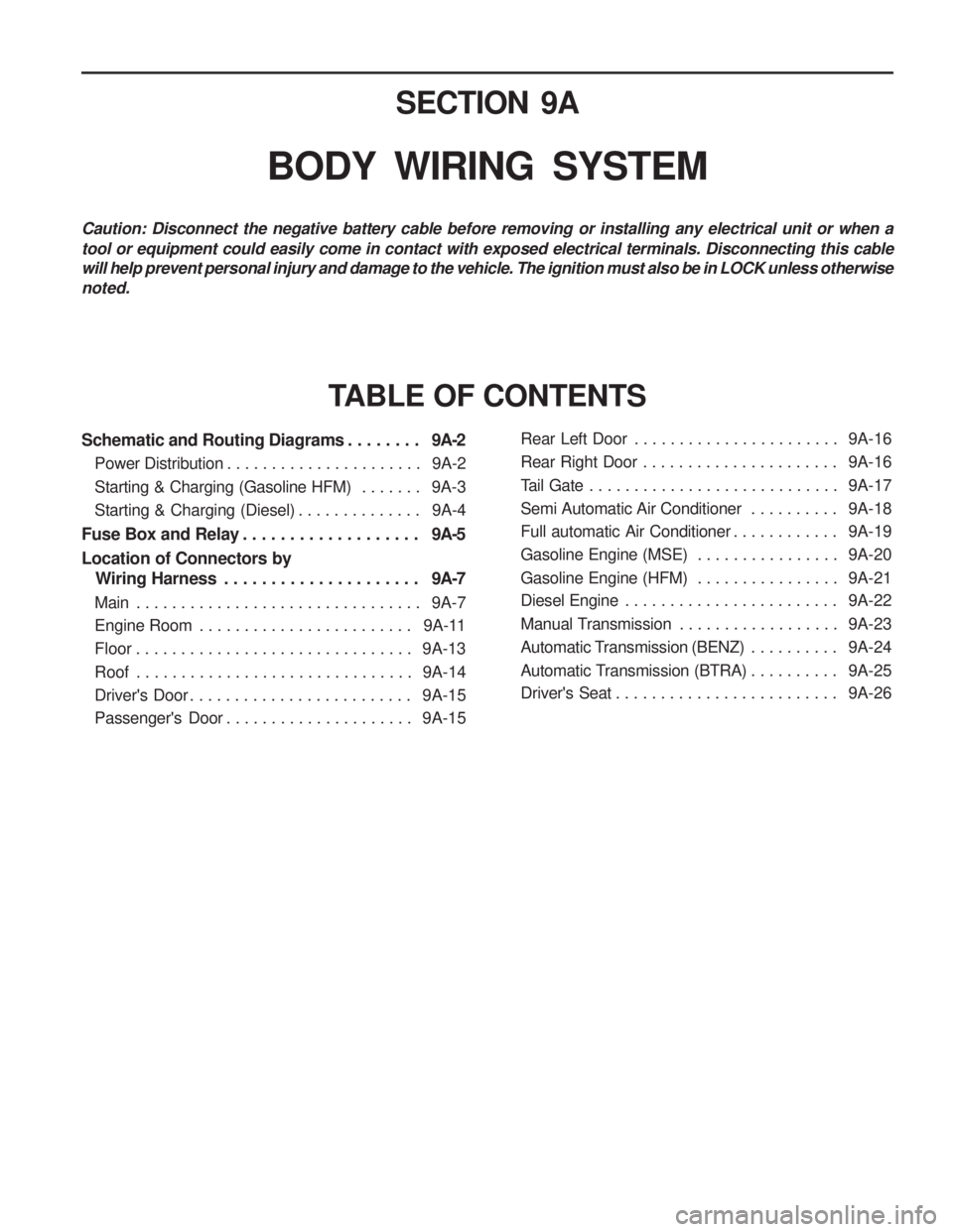
SECTION 9A
BODY WIRING SYSTEM
Schematic and Routing Diagrams . . . . . . . . 9A-2
Power Distribution . . . . . . . . . . . . . . . . . . . . . . 9A-2
Starting & Charging (Gasoline HFM) . . . . . . . 9A-3
Starting & Charging (Diesel) . . . . . . . . . . . . . . 9A-4
Fuse Box and Relay . . . . . . . . . . . . . . . . . . . 9A-5
Location of Connectors by
Wiring Harness . . . . . . . . . . . . . . . . . . . . . 9A-7
Main . . . . . . . . . . . . . . . . . . . . . . . . . . . . . . . . 9A-7
Engine Room . . . . . . . . . . . . . . . . . . . . . . . . 9A-11
Floor . . . . . . . . . . . . . . . . . . . . . . . . . . . . . . . 9A-13
Roof . . . . . . . . . . . . . . . . . . . . . . . . . . . . . . . 9A-14
Driver's Door . . . . . . . . . . . . . . . . . . . . . . . . . 9A-15
Passenger's Door . . . . . . . . . . . . . . . . . . . . . 9A-15
TABLE OF CONTENTS
Caution: Disconnect the negative battery cable before removing or installing any electrical unit or when a tool or equipment could easily come in contact with exposed electrical terminals. Disconnecting this cable will help prevent personal injury and damage to the vehicle. The ignition must also be in LOCK unless otherwisenoted.
Rear Left Door . . . . . . . . . . . . . . . . . . . . . . . 9A-16
Rear Right Door . . . . . . . . . . . . . . . . . . . . . . 9A-16
Tail Gate . . . . . . . . . . . . . . . . . . . . . . . . . . . . 9A-17
Semi Automatic Air Conditioner . . . . . . . . . . 9A-18
Full automatic Air Conditioner . . . . . . . . . . . . 9A-19
Gasoline Engine (MSE) . . . . . . . . . . . . . . . . 9A-20
Gasoline Engine (HFM) . . . . . . . . . . . . . . . . 9A-21
Diesel Engine . . . . . . . . . . . . . . . . . . . . . . . . 9A-22
Manual Transmission . . . . . . . . . . . . . . . . . . 9A-23
Automatic Transmission (BENZ) . . . . . . . . . . 9A-24
Automatic Transmission (BTRA) . . . . . . . . . . 9A-25
Driver's Seat . . . . . . . . . . . . . . . . . . . . . . . . . 9A-26
Page 1210 of 1574
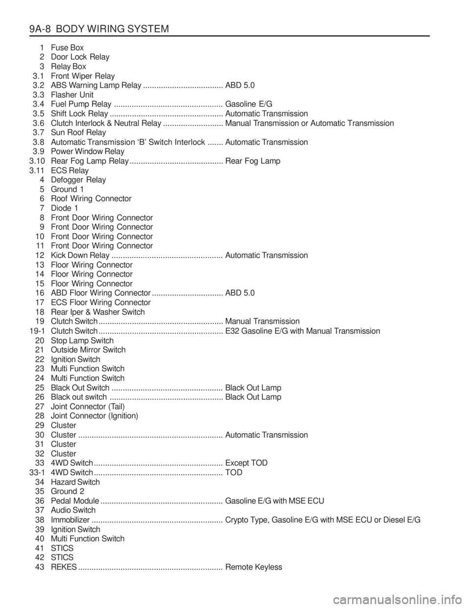
9A-8 BODY WIRING SYSTEM1 Fuse Box
2 Door Lock Relay
3 Relay Box
3.1 Front Wiper Relay
3.2 ABS Warning Lamp Relay ....................................ABD 5.0
3.3 Flasher Unit
3.4 Fuel Pump Relay ................................................. Gasoline E/G
3.5 Shift Lock Relay ................................................... Automatic Transmission
3.6 Clutch Interlock & Neutral Relay ...........................Manual Transmission or Automatic Transmission
3.7 Sun Roof Relay
3.8 Automatic T ransmission ‘B’ Switch Interlock ....... Automatic Transmission
3.9 Power Window Relay
3.10 Rear Fog Lamp Relay .......................................... Rear Fog Lamp
3.11 ECS Relay 4 Defogger Relay
5 Ground 1
6 Roof Wiring Connector
7 Diode 1
8 Front Door Wiring Connector
9 Front Door Wiring Connector
10 Front Door Wiring Connector 11 Front Door Wiring Connector
12 Kick Down Relay .................................................. Automatic Transmission
13 Floor Wiring Connector
14 Floor Wiring Connector
15 Floor Wiring Connector
16 ABD Floor Wiring Connector ................................ABD 5.0
17 ECS Floor Wiring Connector
18 Rear Iper & Washer Switch
19 Clutch Switch ........................................................ Manual Transmission
19-1 Clutch Switch ........................................................ E32 Gasoline E/G with Manual Transmission
20 Stop Lamp Switch
21 Outside Mirror Switch
22 Ignition Switch
23 Multi Function Switch
24 Multi Function Switch
25 Black Out Switch .................................................. Black Out Lamp
26 Black out switch ................................................... Black Out Lamp
27 Joint Connector (Tail)
28 Joint Connector (Ignition)
29 Cluster
30 Cluster ................................................................. Automatic Transmission
31 Cluster
32 Cluster
33 4WD Switch .......................................................... Except TOD
33-1 4WD Switch .......................................................... TOD
3 4 Hazard Switch
35 Ground 2
36 Pedal Module ....................................................... Gasoline E/G with MSE ECU
37 Audio Switch
3 8 Immobilizer ........................................................... Crypto Type, Gasoline E/G with MSE ECU or Diesel E/G
39 Ignition Switch
40 Multi Function Switch
4 1 STICS
4 2 STICS
4 3 REKES ................................................................. Remote Keyless
Page 1211 of 1574
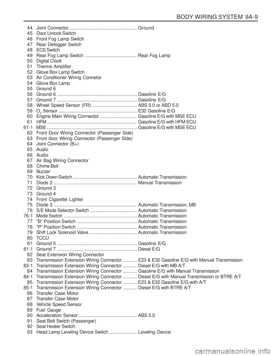
BODY WIRING SYSTEM 9A-9
44 Joint Connector.................................................... Ground
45 Door Unlock Switch
46 Front Fog Lamp Switch
47 Rear Defogger Switch
4 8 ECS Switch
49 Rear Fog Lamp Switch ........................................Rear Fog Lamp
50 Digital Clock
51 Thermo Amplifier
52 Glove Box Lamp Switch
53 Air Conditioner Wiring Connetor
54 Glove Box Lamp
55 Ground 6
56 Ground 6 ............................................................. Gasoline E/G
57 Ground 7 ............................................................. Gasoline E/G
58 Wheel Speed Sensor (FR) ..................................ABS 5.0 or ABD 5.0
59 O 2 Sensor
............................................................ E32 Gasoline E/G
60 Engine Main Wiring Connector ............................Gasoline E/G with MSE ECU
61 HFM ..................................................................... Gasoline E/G with HFM ECU
61-1 MSE ..................................................................... Gasoline E/G with MSE ECU
62 Front Door Wiring Connector (Passenger Side)
63 Front door Wiring Connector (Passenger Side)
64 Joint Connector (B+)
65 Audio
66 Audio
67 Air Bag Wiring Connector
68 Chime Bell
6 9 Buzzer
70 Kick Down Switch ................................................. Automatic Transmission
71 Diode 2 ................................................................ Manual Transmission
72 Ground 3
73 Ground 4
74 Front Cigarette Lighter
75 Diode 3 ................................................................ Automatic Transmission, MB
76 S/E Mode Selector Switch ....................................Automatic Transmission
76-1 Mode Switch ........................................................ Automatic Transmission
77 “B” Position Switch .............................................. Automatic Transmission
78 “P” Position Switch .............................................. Automatic Transmission
79 Shift Lock Solenoid Valve .....................................Automatic Transmission
8 0 TCCU
81 Ground 5 ............................................................. Gasoline E/G
81-1 Ground 7 ............................................................. Diesel E/G
82 Seat Extension Wiring Connector
83 Transmission Extension Wiring Connector ...........E23 & E32 Gasoline E/G with Manual Transmission
83-1 T ransmission Extension Wiring Connector ...........Diesel E/G with MB A/T
84 Transmission Extension Wiring Connector ...........Gasoline E/G with Manual Transmission
84-1 T ransmission Extension Wiring Connector ...........Diesel E/G with Manual Transmission or BTRE A/T
85 Transmission Extension Wiring Connector ...........E23 & E32 Gasoline E/G with A/T
85-1 T ransmission Extension Wiring Connector ...........Diesel E/G with BTRE A/T
86 Transfer Case Motor
87 Transfer Case Motor
88 Vehicle Speed Sensor
89 Fuel Gauge
90 Acceleration Sensor ............................................. ABS 5.0
91 Seat Belt Switch (Passenger)
92 Seat Heater Switch
93 Head Lamp Leveling Device Switch .....................Leveling Device
Page 1225 of 1574
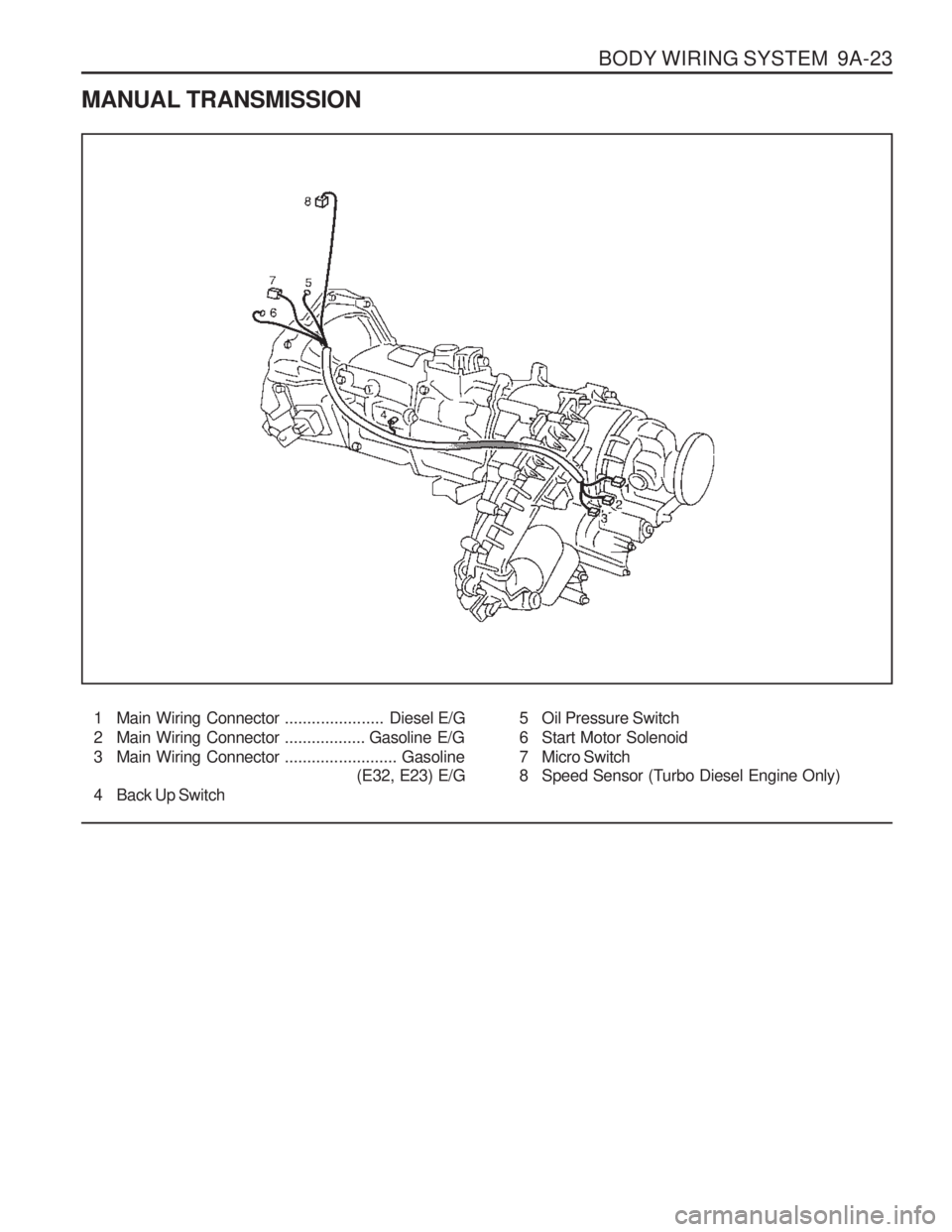
BODY WIRING SYSTEM 9A-23
MANUAL TRANSMISSION1 Main Wiring Connector ......................Diesel E/G
2 Main Wiring Connector ..................Gasoline E/G
3 Main Wiring Connector .........................Gasoline
(E32, E23) E/G
4 Back Up Switch 5 Oil Pressure Switch
6 Start Motor Solenoid
7 Micro Switch
8 Speed Sensor (Turbo Diesel Engine Only)
Page 1315 of 1574
MUSSO-SPORTS 1A-3
SUPPLEMENT
HUBER EGR
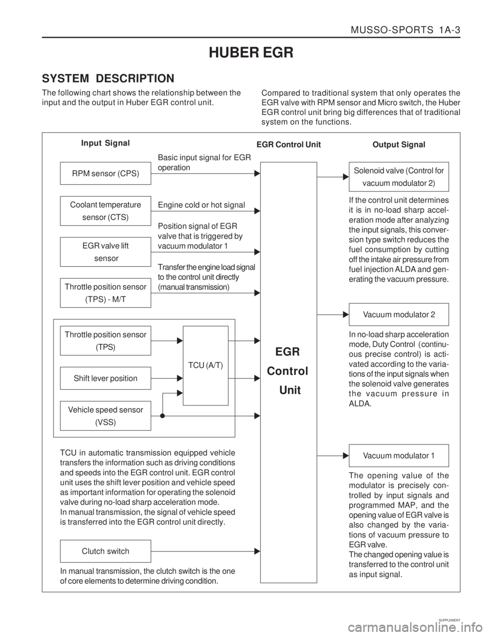
SYSTEM DESCRIPTION The following chart shows the relationship between the input and the output in Huber EGR control unit. Compared to traditional system that only operates theEGR valve with RPM sensor and Micro switch, the HuberEGR control unit bring big differences that of traditionalsystem on the functions.
Input Signal
RPM sensor (CPS)
EGR valve lift sensor
Throttle position sensor (TPS) - M/T
Shift lever position
Throttle position sensor (TPS)
Vehicle speed sensor(VSS) Basic input signal for EGR operation Engine cold or hot signal
Position signal of EGR valve that is triggered by vacuum modulator 1 Transfer the engine load signal to the control unit directly (manual transmission)
TCU (A/T)
EGR
Control
Unit
Coolant temperature sensor (CTS)
Solenoid valve (Control forvacuum modulator 2)
If the control unit determines it is in no-load sharp accel- eration mode after analyzing the input signals, this conver- sion type switch reduces the fuel consumption by cutting off the intake air pressure from
fuel injection ALDA and gen- erating the vacuum pressure. In no-load sharp acceleration
mode, Duty Control ( continu- ous precise control) is acti- vated according to the varia- tions of the input signals when the solenoid valve generates the vacuum pressure in ALDA.
Vacuum modulator 2
The opening value of the modulator is precisely con- trolled by input signals and programmed MAP, and the opening value of EGR valve is also changed by the varia- tions of vacuum pressure to EGR valve. The changed opening value is transferred to the control unit as input signal.
Vacuum modulator 1
TCU in automatic transmission equipped vehicle transfers the information such as driving conditions and speeds into the EGR control unit. EGR control unit uses the shift lever position and vehicle speed as important information for operating the solenoid valve during no-load sharp acceleration mode. In manual transmission, the signal of vehicle speed is transferred into the EGR control unit directly.
Clutch switch
In manual transmission, the clutch switch is the one of core elements to determine driving condition. Output Signal
EGR Control Unit