2003 SSANGYONG MUSSO ECU
[x] Cancel search: ECUPage 1133 of 1574
5D2-44 TRANSFER CASE (TOD)
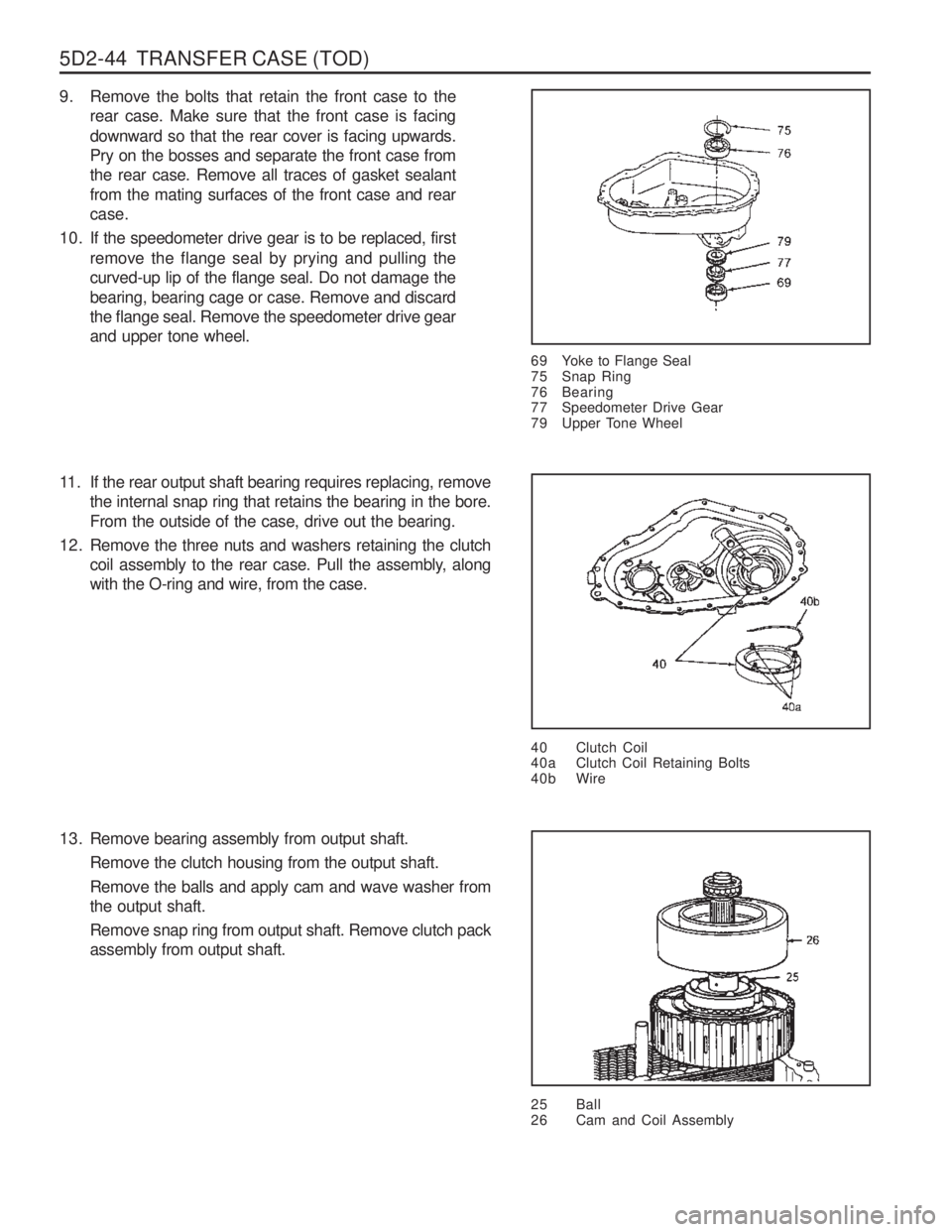
9. Remove the bolts that retain the front case to therear case. Make sure that the front case is facing downward so that the rear cover is facing upwards. Pry on the bosses and separate the front case fromthe rear case. Remove all traces of gasket sealantfrom the mating surfaces of the front case and rearcase.
10. If the speedometer drive gear is to be replaced, first remove the flange seal by prying and pulling thecurved-up lip of the flange seal. Do not damage thebearing, bearing cage or case. Remove and discardthe flange seal. Remove the speedometer drive gearand upper tone wheel.
69 Yoke to Flange Seal
75 Snap Ring
76 Bearing
77 Speedometer Drive Gear
79 Upper Tone Wheel
40 Clutch Coil
40a Clutch Coil Retaining Bolts
40b Wire
11. If the rear output shaft bearing requires replacing, removethe internal snap ring that retains the bearing in the bore. From the outside of the case, drive out the bearing.
12. Remove the three nuts and washers retaining the clutch coil assembly to the rear case. Pull the assembly, alongwith the O-ring and wire, from the case.
13. Remove bearing assembly from output shaft. Remove the clutch housing from the output shaft. Remove the balls and apply cam and wave washer from the output shaft. Remove snap ring from output shaft. Remove clutch pack assembly from output shaft.
25 Ball
26 Cam and Coil Assembly
Page 1137 of 1574
5D2-48 TRANSFER CASE (TOD)
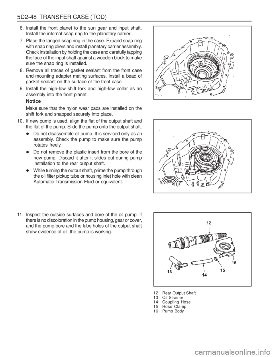
6. Install the front planet to the sun gear and input shaft.Install the internal snap ring to the planetary carrier.
7. Place the tanged snap ring in the case. Expand snap ring with snap ring pliers and install planetary carrier assembly. Check installation by holding the case and carefully tappingthe face of the input shaft against a wooden block to makesure the snap ring is installed.
8. Remove all traces of gasket sealant from the front case and mounting adapter mating surfaces. Install a bead ofgasket sealant on the surface of the front case.
9. Install the high-low shift fork and high-low collar as an assembly into the front planet. Notice Make sure that the nylon wear pads are installed on the shift fork and snapped securely into place.
12 Rear Output Shaft
13 Oil Strainer
14 Coupling Hose
15 Hose Clamp
16 Pump Body
10. If new pump is used, align the flat of the output shaft and
the flat of the pump. Slide the pump onto the output shaft.
�Do not disassemble oil pump. It is serviced only as an
assembly. Check the pump to make sure the pump
rotates freely.
� Do not remove the plastic insert from the bore of the
new pump. Discard it after it slides out during pumpinstallation to the rear output shaft.
� While turning the output shaft, prime the pump through
the oil filter pickup tube or housing inlet hole with clean
Automatic Transmission Fluid or equivalent.
11. Inspect the outside surfaces and bore of the oil pump. If there is no discoloration in the pump housing, gear or cover,and the pump bore and the lube holes of the output shaft show evidence of oil, the pump is working.
Page 1141 of 1574
5D2-52 TRANSFER CASE (TOD)
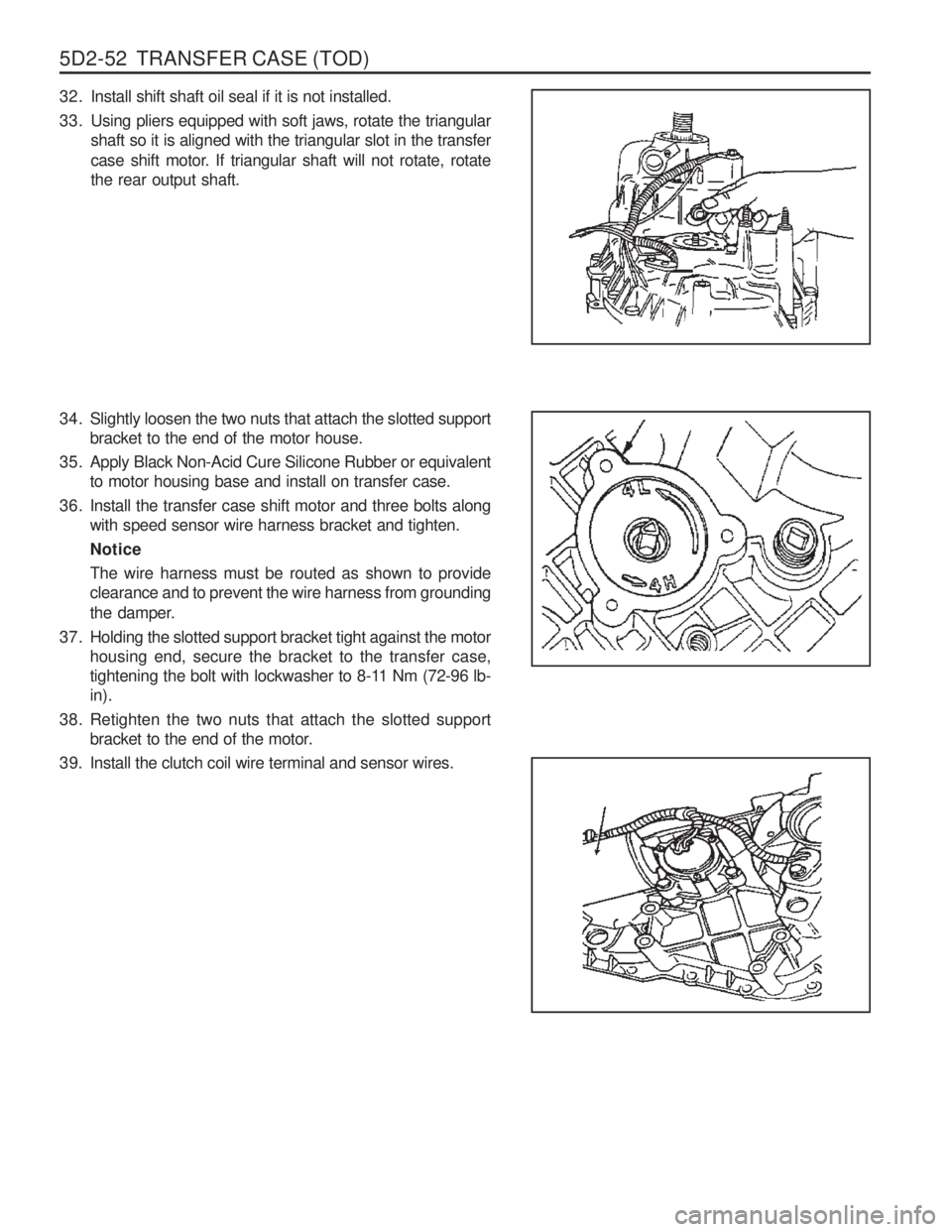
32. Install shift shaft oil seal if it is not installed.
33. Using pliers equipped with soft jaws, rotate the triangularshaft so it is aligned with the triangular slot in the transfer
case shift motor. If triangular shaft will not rotate, rotate the rear output shaft.
34. Slightly loosen the two nuts that attach the slotted support bracket to the end of the motor house.
35. Apply Black Non-Acid Cure Silicone Rubber or equivalent to motor housing base and install on transfer case.
36. Install the transfer case shift motor and three bolts along with speed sensor wire harness bracket and tighten. NoticeThe wire harness must be routed as shown to provide clearance and to prevent the wire harness from grounding
the damper.
37. Holding the slotted support bracket tight against the motor housing end, secure the bracket to the transfer case,
tightening the bolt with lockwasher to 8-11 Nm (72-96 lb-in).
38. Retighten the two nuts that attach the slotted support bracket to the end of the motor.
39. Install the clutch coil wire terminal and sensor wires.
Page 1161 of 1574
FATC-HAVC 7D-5
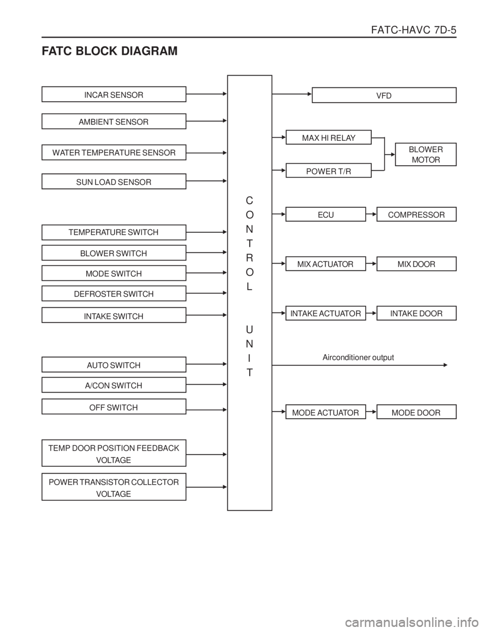
FATC BLOCK DIAGRAM
INCAR SENSOR
AMBIENT SENSOR
WATER TEMPERATURE SENSOR
SUN LOAD SENSOR
TEMPERATURE SWITCH
BLOWER SWITCH
MODE SWITCH
DEFROSTER SWITCH
INTAKE SWITCH
AUTO SWITCH
A/CON SWITCH
OFF SWITCH
TEMP DOOR POSITION FEEDBACKVOLTAGE
POWER TRANSISTOR COLLECTORVOLTAGE
VFD
MAX HI RELAY
POWER T/R
BLOWERMOTOR
ECUCOMPRESSOR
MIX ACTUATORMIX DOOR
INTAKE ACTUATORINTAKE DOOR
MODE ACTUATORMODE DOOR
Airconditioner output
C ON
T
RO L
UN I
T
Page 1180 of 1574
8A-4 SEAT BELTGENERAL DESCRIPTION
AND SYSTEM OPERATION
DRIVER SEAT BELT WARNING The driver's safety belt incorporates a safety belt reminder light in the instment cluster remind the driver if the safety beltis not fastened when the ignition is turnd ON.
OPERATION AND FUNCTIONAL CHECKS Caution :
� Keep sharp objects and potentially damaging objects away from the seat belts.
� Avoid bending or damaging any portion of the buckleor the latch plate.
� Do not bleach or dye the belt webbing. Use only mild soap and water in order to clean the belts.
� When installing the seat belt anchor bolts and thescrews, start the bolts and screws by hand in order to prevent crossthreading.
� Do not attempt any repairs on the retractormechsemblies with new assemblies.
� Replace any belts that are cut r damaged in any way.
1. Inspect all saet belt anchor bolts and the screw in order to verify that they are secure.
2. Inspect the seat belt buckle. The buckle must lock and unlock easily.
3. After inserting the latch into the buckle, tug sharply on the belt. The buckle must remain locked.
4. Fully extend the shoulder belt portion to make sure that there is no twisting or tears in the belt.
5. Let the shoulder belt retract fully. The belt should retract easily.
Page 1183 of 1574
SUPPLEMENTAL RESTRAINT SYSTEM(SRS) 8B-3
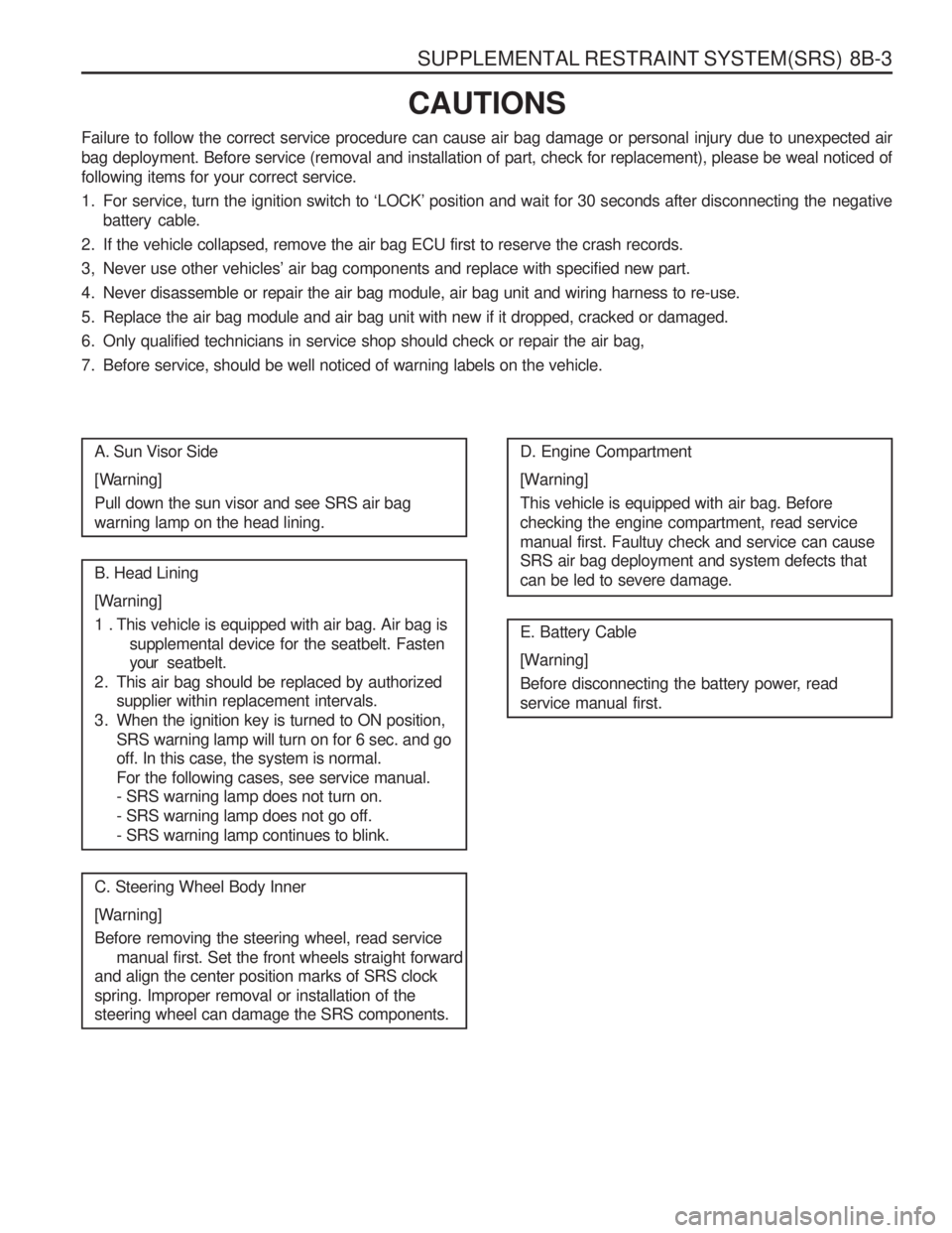
CAUTIONS
Failure to follow the correct service procedure can cause air bag damage or personal injury due to unexpected air
bag deployment. Before service (removal and installation of part, check for replacement), please be weal noticed offollowing items for your correct service.
1. For service, turn the ignition switch to ‘LOCK’ position and wait for 30 seconds after disconnecting the negative battery cable.
2. If the vehicle collapsed, remove the air bag ECU first to reserve the crash records.
3, Never use other vehicles’ air bag components and replace with specified new part.
4. Never disassemble or repair the air bag module, air bag unit and wiring harness to re-use.
5. Replace the air bag module and air bag unit with new if it dropped, cracked or damaged.
6. Only qualified technicians in service shop should check or repair the air bag,
7. Before service, should be well noticed of warning labels on the vehicle.
A. Sun Visor Side
[Warning] Pull down the sun visor and see SRS air bag warning lamp on the head lining. B. Head Lining
[Warning]
1 . This vehicle is equipped with air bag. Air bag is supplemental device for the seatbelt. Fasten your seatbelt.
2. This air bag should be replaced by authorized supplier within replacement intervals.
3. When the ignition key is turned to ON position, SRS warning lamp will turn on for 6 sec. and go off. In this case, the system is normal. For the following cases, see service manual. - SRS warning lamp does not turn on. - SRS warning lamp does not go off.- SRS warning lamp continues to blink.
C. Steering Wheel Body Inner
[Warning] Before removing the steering wheel, read service manual first. Set the front wheels straight forward
and align the center position marks of SRS clock spring. Improper removal or installation of the steering wheel can damage the SRS components. D. Engine Compartment
[Warning] This vehicle is equipped with air bag. Before checking the engine compartment, read servicemanual first. Faultuy check and service can cause SRS air bag deployment and system defects that can be led to severe damage. E. Battery Cable
[Warning]
Before disconnecting the battery power, read service manual first.
Page 1191 of 1574
SUPPLEMENTAL RESTRAINT SYSTEM(SRS) 8B-11
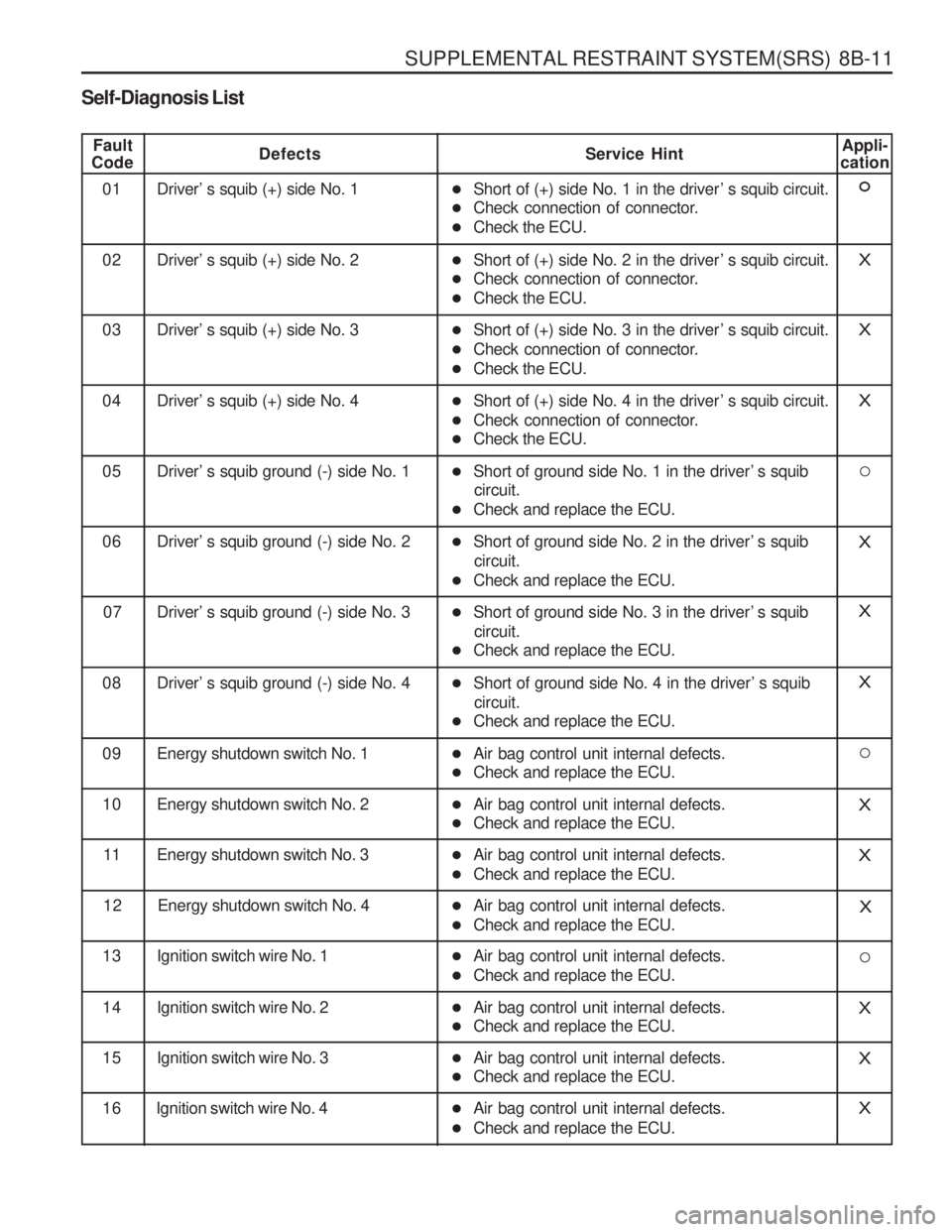
Self-Diagnosis List
Fault
CodeDefects Service Hint
01 Driver’ s squib (+) side No. 1 �Short of (+) side No. 1 in the driver ’ s squib circuit.
� Check connection of connector.
� Check the ECU.Appli-
cation
02 Driver’ s squib (+) side No. 2 �Short of (+) side No. 2 in the driver ’ s squib circuit.
� Check connection of connector.
� Check the ECU.X
03 Driver’ s squib (+) side No. 3 �Short of (+) side No. 3 in the driver ’ s squib circuit.
� Check connection of connector.
� Check the ECU.X
04 Driver’ s squib (+) side No. 4 �Short of (+) side No. 4 in the driver ’ s squib circuit.
� Check connection of connector.
� Check the ECU.X
05 Driver’ s squib ground (-) side No. 1 �Short of ground side No. 1 in the driver ’ s squib
circuit.
� Check and replace the ECU.
06 Driver’ s squib ground (-) side No. 2 �Short of ground side No. 2 in the driver ’ s squib
circuit.
� Check and replace the ECU.X
07 Driver’ s squib ground (-) side No. 3 �Short of ground side No. 3 in the driver ’ s squib
circuit.
� Check and replace the ECU.X
08 Driver’ s squib ground (-) side No. 4 �Short of ground side No. 4 in the driver ’ s squib
circuit.
� Check and replace the ECU.X
09 Energy shutdown switch No. 1 �Air bag control unit internal defects.
� Check and replace the ECU.
10 Energy shutdown switch No. 2 �Air bag control unit internal defects.
� Check and replace the ECU.X
11 Energy shutdown switch No. 3 �Air bag control unit internal defects.
� Check and replace the ECU.X
12 Energy shutdown switch No. 4 �Air bag control unit internal defects.
� Check and replace the ECU.X
13 Ignition switch wire No. 1 �Air bag control unit internal defects.
� Check and replace the ECU.
14 Ignition switch wire No. 2 �Air bag control unit internal defects.
� Check and replace the ECU.X
15 Ignition switch wire No. 3 �Air bag control unit internal defects.
� Check and replace the ECU.X
16 Ignition switch wire No. 4X�Air bag control unit internal defects.
� Check and replace the ECU.
Page 1192 of 1574
8B-12 SUPPLEMENTAL RESTRAINT SYSTEM(SRS)
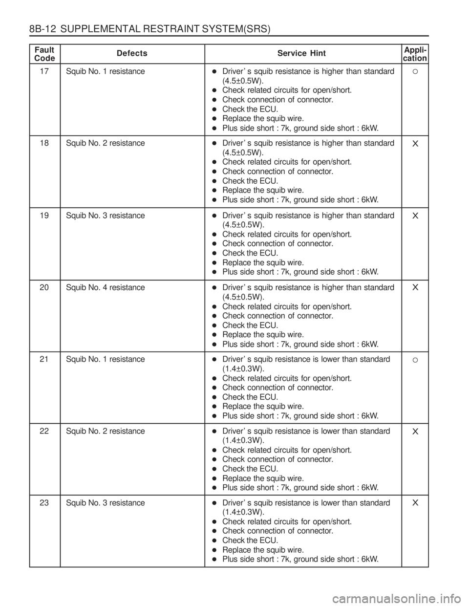
Fault
CodeDefects Service HintAppli-
cation
17 Squib No. 1 resistance
18 Squib No. 2 resistanceX
19 Squib No. 3 resistanceX
20 Squib No. 4 resistanceX
21 Squib No. 1 resistance
22 Squib No. 2 resistanceX
� Driver ’ s squib resistance is higher than standard (4.5±0.5W).
� Check related circuits for open/short.
� Check connection of connector.
� Check the ECU.
� Replace the squib wire.
� Plus side short : 7k, ground side short : 6kW.
� Driver ’ s squib resistance is higher than standard(4.5±0.5W).
� Check related circuits for open/short.
� Check connection of connector.
� Check the ECU.
� Replace the squib wire.
� Plus side short : 7k, ground side short : 6kW.
� Driver ’ s squib resistance is higher than standard (4.5±0.5W).
� Check related circuits for open/short.
� Check connection of connector.
� Check the ECU.
� Replace the squib wire.
� Plus side short : 7k, ground side short : 6kW.
� Driver ’ s squib resistance is higher than standard (4.5±0.5W).
� Check related circuits for open/short.
� Check connection of connector.
� Check the ECU.
� Replace the squib wire.
� Plus side short : 7k, ground side short : 6kW.
� Driver ’ s squib resistance is lower than standard(1.4±0.3W).
� Check related circuits for open/short.
� Check connection of connector.
� Check the ECU.
� Replace the squib wire.
� Plus side short : 7k, ground side short : 6kW.
� Driver ’ s squib resistance is lower than standard (1.4±0.3W).
� Check related circuits for open/short.
� Check connection of connector.
� Check the ECU.
� Replace the squib wire.
� Plus side short : 7k, ground side short : 6kW.
23 Squib No. 3 resistanceX�Driver ’ s squib resistance is lower than standard (1.4±0.3W).
� Check related circuits for open/short.
� Check connection of connector.
� Check the ECU.
� Replace the squib wire.
� Plus side short : 7k, ground side short : 6kW.