Page 3673 of 4179

STARTING SYSTEM
SC-29
C
D
E
F
G
H
I
J
L
MA
B
SC
InspectionEKS0031L
MAGNETIC SWITCH CHECK
�Before starting to check, disconnect the battery cable from the negative terminal.
�Disconnect “M” terminal of starter motor.
1. Continuity test (between “S” terminal and switch body).
�No continuity... Replace.
2. Continuity test (between “S” terminal and “M” terminal).
�No continuity... Replace.
PINION/CLUTCH CHECK
1. Inspect pinion teeth.
�Replace pinion if teeth are worn or damaged. (Also check
condition of ring gear teeth.)
2. Inspect reduction gear teeth (If equipped).
�Replace reduction gear if teeth are worn or damaged. (Also
check condition of armature shaft gear teeth.)
3. Check to see if pinion locks in one direction and rotates
smoothly in the opposite direction.
�If it locks or rotates in both directions, or unusual resistance is
evident.... Replace.
BRUSH CHECK
Brush
Check wear of brush.
�Excessive wear... Replace.
SEL555E
SEL556E
MEL139L
Wear limit length : Refer to SDS. SC-34, "Starter" .
SEL014Z
Page 3674 of 4179
SC-30
STARTING SYSTEM
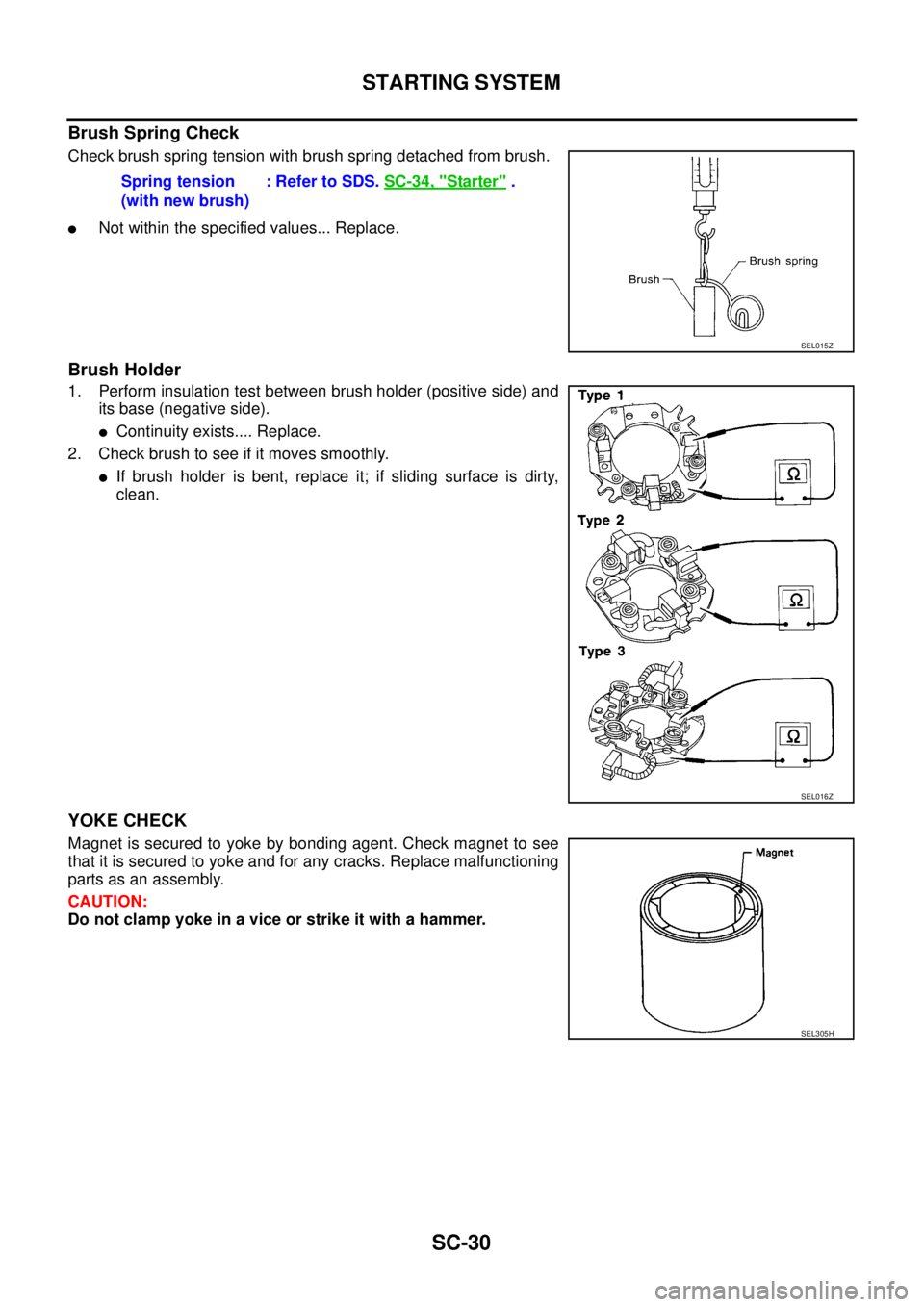
Brush Spring Check
Check brush spring tension with brush spring detached from brush.
�Not within the specified values... Replace.
Brush Holder
1. Perform insulation test between brush holder (positive side) and
its base (negative side).
�Continuity exists.... Replace.
2. Check brush to see if it moves smoothly.
�If brush holder is bent, replace it; if sliding surface is dirty,
clean.
YOKE CHECK
Magnet is secured to yoke by bonding agent. Check magnet to see
that it is secured to yoke and for any cracks. Replace malfunctioning
parts as an assembly.
CAUTION:
Do not clamp yoke in a vice or strike it with a hammer.Spring tension
(with new brush): Refer to SDS. SC-34, "
Starter" .
SEL015Z
SEL016Z
SEL305H
Page 3675 of 4179
STARTING SYSTEM
SC-31
C
D
E
F
G
H
I
J
L
MA
B
SC
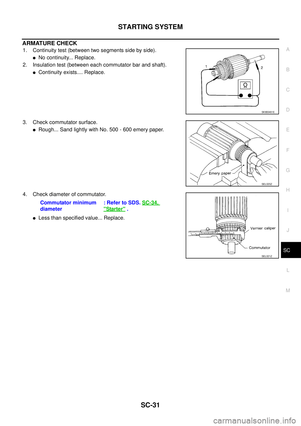
ARMATURE CHECK
1. Continuity test (between two segments side by side).
�No continuity... Replace.
2. Insulation test (between each commutator bar and shaft).
�Continuity exists.... Replace.
3. Check commutator surface.
�Rough... Sand lightly with No. 500 - 600 emery paper.
4. Check diameter of commutator.
�Less than specified value... Replace.
SKIB0461E
SEL020Z
Commutator minimum
diameter: Refer to SDS. SC-34,
"Starter" .
SEL021Z
Page 3676 of 4179
SC-32
STARTING SYSTEM
5. Check depth of insulating mold from commutator surface.
�Less than 0.2 mm (0.008 in)... Undercut to 0.5 to 0.8 mm
(0.020 to 0.031 in).
AssemblyEKS0031M
Apply high-temperature grease to lubricate the bearing, gears and frictional surface when assembling the
starter.
Carefully observe the following instructions.
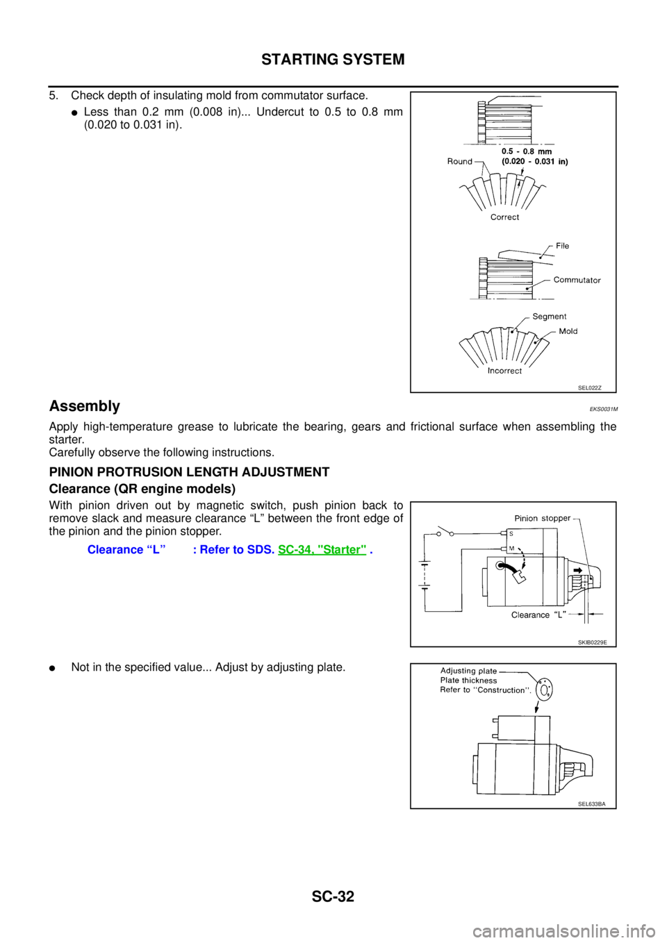
PINION PROTRUSION LENGTH ADJUSTMENT
Clearance (QR engine models)
With pinion driven out by magnetic switch, push pinion back to
remove slack and measure clearance “L” between the front edge of
the pinion and the pinion stopper.
�Not in the specified value... Adjust by adjusting plate.
SEL022Z
Clearance “L” : Refer to SDS. SC-34, "Starter" .
SKIB0229E
SEL633BA
Page 3677 of 4179
STARTING SYSTEM
SC-33
C
D
E
F
G
H
I
J
L
MA
B
SC
Movement (YD engine models)
Compare movement “L” in height of pinion when it is pushed out with
magnetic switch energized and when it is pulled out by hand until it
touches stopper.
�Not in the specified value...Adjust by adjusting plate.Movement “L” : Refer to SDS. SC-34, "
Starter" .
SKIB0230E
SEL633BA
Page 3678 of 4179

SERVICE DATA AND SPECIFICATIONS (SDS)PFP:00030
BatteryEKS0031Q
StarterEKS0031R
AlternatorEKS0031S
Applied modelQR20, QR25 engine
YD22 engine
Except
for N")
SC-34
SERVICE DATA AND SPECIFICATIONS (SDS)
SERVICE DATA AND SPECIFICATIONS (SDS)PFP:00030
BatteryEKS0031Q
StarterEKS0031R
AlternatorEKS0031S
Applied modelQR20, QR25 engine
YD22 engine
Except
for Northern EuropeFor Northern
Europe
Type 55D23L 80D23L 110D26L
Capacity [V - AH] 12-48 12-52 12-64
Applied modelQR20, QR25 engine
YD22 engine
A/T M/T
Ty p eS114-844 M0T87081 M8T71471
HITACHI make MITSUBISHI make
Reduction
System voltage [V] 12
No-loadTerminal voltage [V] 11.0
Current [A] Less than 90 Less than 90 Less than 145
Revolution [rpm] More than 2,700 More than 2,500 More than 3,300
Minimum diameter of commutator [mm (in)] 28.0 (1.102) 28.8 (1.134) 31.4 (1.236)
Minimum length of brush [mm (in)] 10.5 (0.413) 7.0 (0.276) 11.0 (0.433)
Brush spring tension [N (kg, lb)] 16.2 (1.65, 3.64)15.0 - 20.4
(1.5 - 2.1, 3.4 - 4.6)26.7 - 36.1
(2.7 - 3.7, 6.0 - 8.2)
Clearance between bearing metal and armature shaft [mm (in)] Less than 0.2 (0.008) —
Clearance “L” between pinion front edge and pinion
stopper[mm (in)]0.3 - 2.5
(0.012 - 0.098)0.5 - 2.0
(0.020 - 0.079)—
Movement “L” in height of pinion assembly [mm (in)] —0.5 - 2.0
(0.020 - 0.079)
Applied model QR20, QR25 engine YD22 engine
Ty p eLR1110-713 A3TB0771
HITACHI make MITSUBISHI make
Nominal rating [V - A] 12-110 12-90
Ground polarityNegative
Minimum revolutions under no-load
(When 13.5 V is applied)[rpm] Less than 1,100 Less than 1,300
Hot output current (When 13.5V is applied) [A/rpm](More than 35/1,300)
More than 70/1,800
More than 91/2,500
More than 110/5,000More than 29/1,300
More than 76/2,500
More than 88/5,000
Regulated output voltage [V] 14.1 - 14.7
Minimum length of brush [mm (in)] More than 6.0 (0.236) More than 5.0 (0.197)
Brush spring pressure [N (g, oz)]1.0 - 3.43
(102 - 350, 3.60 - 12.34)4.8 - 6.0
(490 - 610, 17.28 - 21.51)
Slip ring minimum diameter [mm (in)] More than 26.0 (1.024) More than 22.1 (0.870)
Rotor coil resistance at 20 °C (68 °F) [Ω] 2.31 2.1 - 2.5
Page 3682 of 4179

DI-4
COMBINATION METERS
COMBINATION METERSPFP:24814
System DescriptionEKS00EGZ
UNIFIED CONTROL METER
�Speedometer, odo/trip meter, tachometer, fuel gauge and water temperature gauge are controlled by the
unified meter control unit, which is built into the combination meter.
�Digital meter is adopted for odo/trip meter.*
*The record of the odo meter is kept even if the battery cable is disconnected. The record of the trip meter
is erased when the battery cable is disconnected.
�Odo/trip meter segments can be checked in diagnosis mode.
�Meter/gauge can be checked in diagnosis mode.
HOW TO CHANGE THE DISPLAY FOR ODO/TRIP METER
�The vehicle speed signal and the memory signals from the meter memory circuit are processed by the
combination meter and the mileage is displayed.
�Ambient temperature indicator indicates signal from ambient sensor processed by combination meter.
�Depressing the odo/trip meter switch toggles the mode in the following order.
�The odo/trip meter display mode toggling and trip display resetting can be identified by the amount of time
that elapses from pressing the odo/trip meter switch to releasing it.
�When resetting with trip A displayed, only trip A display is reset (Trip B operates the same way).
POWER SUPPLY AND GROUND CIRCUIT
Power is supplied at all times
�through 10A fuse [No. 28, located in the fuse block (J/B)]
�to combination meter terminal 1.
With the ignition switch in the ON or START position, power is supplied
�through 10A fuse [No. 11, located in the fuse block (J/B)]
�to combination meter terminals 2.
Ground is supplied
�to combination meter terminals 21
�through body grounds M27 and M70.
WATER TEMPERATURE GAUGE
The water temperature gauge indicates the engine coolant temperature.
ECM provides an engine coolant temperature signal to combination meter for water temperature gauge with
CAN communication line.
SKIA8917E
Page 3732 of 4179

DI-54
WARNING CHIME
WARNING CHIMEPFP:24814
System DescriptionEKS002XF
POWER SUPPLY AND GROUND CIRCUIT
Power is supplied at all times
�to combination switch terminal 11 and
�to daytime light control unit terminal 1 (with daytime light system)
�through 10A fuse (No. 31, located in fuse and fusible link box), and
�to key switch terminal 1 (RHD models) and
�to time control unit terminal 1
�through 10A fuse [No. 28, located in the fuse block (J/B)].
With ignition switch in ON or START position, power is supplied
�to time control unit terminal 17
�through 10A fuse [No. 5, located in the fuse block (J/B)].
Ground is supplied
�to time control unit terminal 16
�through grounds M27 and M70.
LIGHT WARNING CHIME
With ignition switch OFF position, driver's door open, and lighting switch in 1ST or 2ND position, warning
chime will sound. Power is supplied
�from the lighting switch terminal 12 or daytime light control unit terminal 11 (with daytime light system)
�to time control unit terminal 19.
Ground is supplied
�to time control unit terminal 30
�through front door switch (driver side) terminal 2.
Front door switch (driver side) terminal 3 is grounded through grounds B8 and B18.
SEAT BELT WARNING CHIME
When the vehicle speed exceeds 25 km/h (16 MPH) with driver side or passenger seat belt unfastened (seat
belt switch ON), warning chime will sound. Refer to SB-6, "
SEAT BELT WARNING SYSTEM" .
KEY REMINDER WARNING CHIME [FOR RHD MODELS]
Key reminder chime will sound, at the same time, key reminder system will start operating.
When the following three conditions are simultaneously met.
�Key is inserted in the ignition key cylinder.
�Driver`s door is opened.
�The setting of driver`s door lock knob is “LOCK”.
For information regarding key reminder system, refer to BL-43, "
Key reminder system" in BL section.

Compare movement “L” in height of pinion when it is pushed out with
magnetic switch energized and when it is pulled ou")