Page 2475 of 4179
DISASSEMBLY
AT-439
[ALL]
D
E
F
G
H
I
J
K
L
MA
B
AT
45. Remove return spring and parking pawl spacer with flat-bladed
screwdriver from parking shaft.
46. Draw out parking shaft and remove parking pawl from transaxle
case.
47. Check parking pawl and shaft for damage or wear.
48. Remove parking actuator support from transaxle case.
49. Check parking actuator support for damage or wear.
50. Remove LH differential side oil seal with flat-bladed screwdriver
from transaxle case.
CAUTION:
Be careful not to scratch transaxle case.
SCIA4881E
SAT066D
SAT040F
Page 2539 of 4179
REPAIR FOR COMPONENT PARTS
AT-503
[ALL]
D
E
F
G
H
I
J
K
L
MA
B
AT
Final DriveECS00ECB
COMPONENTS
DISASSEMBLY
1. Remove final gear.
2. Press out differential side bearings.
CAUTION:
Be careful not to mix up the right and left bearings.
1. Pinion mate gear 2. Pinion mate gear thrust washer 3. Pinion mate shaft
4. Lock pin 5. Side gear 6. Side gear thrust washer
7. Differential side bearing 8. Differential case 9. Final gear
10. Differential side bearing 11. Differential side bearing adjusting
shim
SCIA3346E
SMT505B
SMT744AA
Page 2540 of 4179
AT-504
[ALL]
REPAIR FOR COMPONENT PARTS
3. Remove differential side bearing outer race, and side bearing
adjusting shim from transaxle case.
4. Drive out lock pin.
5. Draw out pinion mate shaft.
6. Remove pinion mate gears, pinion mate gear thrust washers,
side gears and side gear thrust washers.
INSPECTION
Gear, Washer, Shaft and Case
�Check mating surfaces of differential case, side gears, pinion
mate gears and pinion mate shaft.
�Check washers for wear.
SAT010FA
SAT904DA
SAT316D
SAT544F
Page 2541 of 4179
REPAIR FOR COMPONENT PARTS
AT-505
[ALL]
D
E
F
G
H
I
J
K
L
MA
B
AT
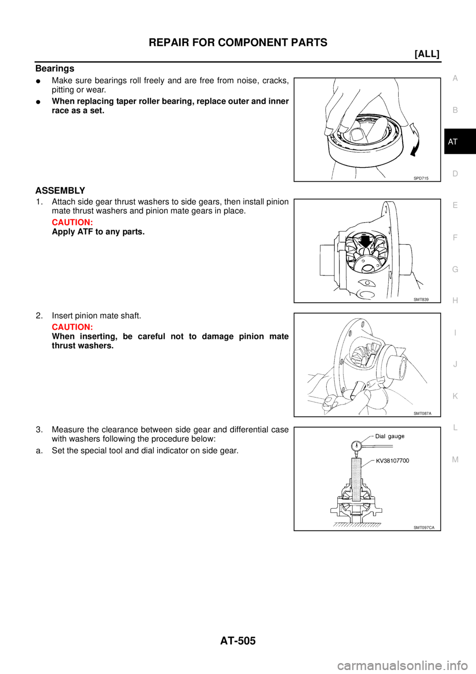
Bearings
�Make sure bearings roll freely and are free from noise, cracks,
pitting or wear.
�When replacing taper roller bearing, replace outer and inner
race as a set.
ASSEMBLY
1. Attach side gear thrust washers to side gears, then install pinion
mate thrust washers and pinion mate gears in place.
CAUTION:
Apply ATF to any parts.
2. Insert pinion mate shaft.
CAUTION:
When inserting, be careful not to damage pinion mate
thrust washers.
3. Measure the clearance between side gear and differential case
with washers following the procedure below:
a. Set the special tool and dial indicator on side gear.
SPD715
SMT839
SMT087A
SMT097CA
Page 2542 of 4179
AT-506
[ALL]
REPAIR FOR COMPONENT PARTS
b. Move side gear up and down to measure dial indicator deflec-
tion. Always measure indicator deflection on both side gears.
c. If not within specification, adjust the clearance by changing the
thickness of differential side gear thrust washers. Refer to AT-
535, "Final Drive" .
4. Install lock pin.
CAUTION:
�Do not reuse lock pin.
�Make sure that lock pin is flush with case.
5. Press on differential side bearings.
CAUTION:
Apply ATF to differential side bearings.
6. Install differential side bearing outer race and differential side
bearing adjusting shim on transaxle case. Refer to AT- 5 0 8 ,
"Adjustment (1)" .
7. Tighten final gear and tighten fixing bolts to the specified torque
in numerical order shown in the figure after temporarily tighten-
ing them. Refer to AT- 5 0 3 , "
COMPONENTS" . Clearance between side gear and differential case
with washer:
0.1 - 0.2 mm (0.004 - 0.008 in)
SMT611A
SMT699BA
SAT545FA
ATM0432D
Page 2543 of 4179
ASSEMBLY
AT-507
[ALL]
D
E
F
G
H
I
J
K
L
MA
B
AT
ASSEMBLYPFP:00000
Assembly (1)ECS004MD
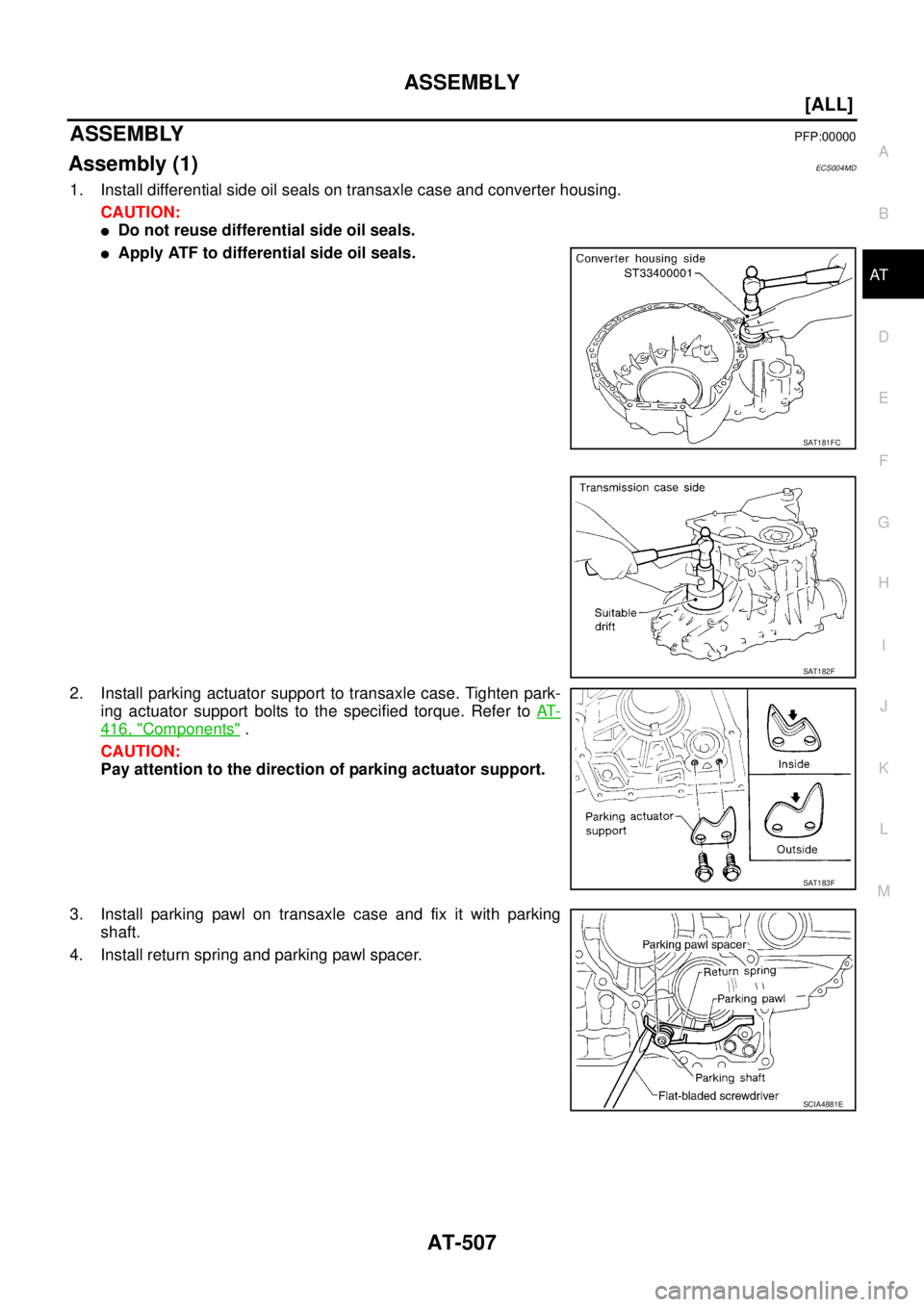
1. Install differential side oil seals on transaxle case and converter housing.
CAUTION:
�Do not reuse differential side oil seals.
�Apply ATF to differential side oil seals.
2. Install parking actuator support to transaxle case. Tighten park-
ing actuator support bolts to the specified torque. Refer to AT-
416, "Components" .
CAUTION:
Pay attention to the direction of parking actuator support.
3. Install parking pawl on transaxle case and fix it with parking
shaft.
4. Install return spring and parking pawl spacer.
SAT181FC
SAT182F
SAT183F
SCIA4881E
Page 2544 of 4179
![NISSAN X-TRAIL 2003 Service Repair Manual AT-508
[ALL]
ASSEMBLY
Adjustment (1)ECS004ME
DIFFERENTIAL SIDE BEARING PRELOAD
1. Install differential side bearing outer race without differential side
bearing adjusting shim on transaxle case.
CAU](/manual-img/5/57404/w960_57404-2543.png "NISSAN X-TRAIL 2003 Service Repair Manual AT-508
[ALL]
ASSEMBLY
Adjustment (1)ECS004ME
DIFFERENTIAL SIDE BEARING PRELOAD
1. Install differential side bearing outer race without differential side
bearing adjusting shim on transaxle case.
CAU")
AT-508
[ALL]
ASSEMBLY
Adjustment (1)ECS004ME
DIFFERENTIAL SIDE BEARING PRELOAD
1. Install differential side bearing outer race without differential side
bearing adjusting shim on transaxle case.
CAUTION:
Apply ATF to differential side bearing outer race.
2. Install differential side bearing outer race on converter housing.
CAUTION:
Apply ATF to differential side bearing outer race.
3. Place final drive assembly on transaxle case.
4. Install transaxle case on converter housing. Tighten transaxle
case fixing bolts to the specified torque. Refer to AT- 4 1 6 , "
Com-
ponents" .
5. Attach dial indicator on differential case at converter housing
side.
6. Insert Tool into differential side gear from transaxle case side.
7. Move SST up and down and measure dial indicator deflection.
8. Select proper thickness of differential side bearing adjusting
shim(s). Refer to AT- 5 3 6 , "
DIFFERENTIAL SIDE BEARING
PRELOAD ADJUSTING SHIMS" .
Suitable shim thickness = Dial indicator deflection + Speci-
fied bearing preload
SAT870D
ATM0024D
Bearing preload:
0.05 - 0.09 mm (0.0020 - 0.0035 in)
SAT186FA
Page 2545 of 4179
![NISSAN X-TRAIL 2003 Service Repair Manual ASSEMBLY
AT-509
[ALL]
D
E
F
G
H
I
J
K
L
MA
B
AT
9. Remove converter housing from transaxle case.
10. Remove final drive assembly from transaxle case.
11. Remove differential side bearing outer race](/manual-img/5/57404/w960_57404-2544.png "NISSAN X-TRAIL 2003 Service Repair Manual ASSEMBLY
AT-509
[ALL]
D
E
F
G
H
I
J
K
L
MA
B
AT
9. Remove converter housing from transaxle case.
10. Remove final drive assembly from transaxle case.
11. Remove differential side bearing outer race")
ASSEMBLY
AT-509
[ALL]
D
E
F
G
H
I
J
K
L
MA
B
AT
9. Remove converter housing from transaxle case.
10. Remove final drive assembly from transaxle case.
11. Remove differential side bearing outer race from transaxle case.
12. Reinstall differential side bearing outer race and differential side
bearing adjusting shim selected from SDS table on transaxle
case. Refer to AT- 5 3 6 , "
DIFFERENTIAL SIDE BEARING PRE-
LOAD ADJUSTING SHIMS" .
13. Reinstall converter housing on transaxle case and tighten con-
verter housing mounting bolts to the specified torque. Refer to
AT- 4 1 6 , "
Components" .
14. Insert SST and measure turning torque of final drive assembly.
�Turn final drive assembly in both directions several times
to seat bearing rollers correctly.
�When old bearing is used again, turning torque will be
slightly less than the above.
�Make sure torque is close to the specified range.
REDUCTION PINION GEAR BEARING PRELOAD
1. Remove converter housing and final drive assembly from tran-
saxle case.
2. Select proper thickness of reduction pinion gear adjusting shim
using the following procedures.
a. Place reduction pinion gear on transaxle case as shown.
b. Place idler gear bearing on transaxle case.
c. Measure the dimensions “B” “C” and “D” and calculate dimen-
sion “A”.
SAT010FC
Turning torque of final drive assembly (New bearing):
0.78 - 1.37 N-m (0.8 - 14.0 kg-cm, 6.9 - 12.2 in-lb)
Preload adapter: KV38105210
SAT188FA
SAT332DA
A = D − (B + C)
“A”: Distance between the surface of idler gear bear-
ing inner race and the adjusting shim mating
surface of reduction pinion gear.
SAT333DA
![NISSAN X-TRAIL 2003 Service Repair Manual DISASSEMBLY
AT-439
[ALL]
D
E
F
G
H
I
J
K
L
MA
B
AT
45. Remove return spring and parking pawl spacer with flat-bladed
screwdriver from parking shaft.
46. Draw out parking shaft and remove parking paw](/manual-img/5/57404/w960_57404-2474.png "NISSAN X-TRAIL 2003 Service Repair Manual DISASSEMBLY
AT-439
[ALL]
D
E
F
G
H
I
J
K
L
MA
B
AT
45. Remove return spring and parking pawl spacer with flat-bladed
screwdriver from parking shaft.
46. Draw out parking shaft and remove parking paw")
![NISSAN X-TRAIL 2003 Service Repair Manual REPAIR FOR COMPONENT PARTS
AT-503
[ALL]
D
E
F
G
H
I
J
K
L
MA
B
AT
Final DriveECS00ECB
COMPONENTS
DISASSEMBLY
1. Remove final gear.
2. Press out differential side bearings.
CAUTION:
Be careful not to](/manual-img/5/57404/w960_57404-2538.png "NISSAN X-TRAIL 2003 Service Repair Manual REPAIR FOR COMPONENT PARTS
AT-503
[ALL]
D
E
F
G
H
I
J
K
L
MA
B
AT
Final DriveECS00ECB
COMPONENTS
DISASSEMBLY
1. Remove final gear.
2. Press out differential side bearings.
CAUTION:
Be careful not to")
![NISSAN X-TRAIL 2003 Service Repair Manual AT-504
[ALL]
REPAIR FOR COMPONENT PARTS
3. Remove differential side bearing outer race, and side bearing
adjusting shim from transaxle case.
4. Drive out lock pin.
5. Draw out pinion mate shaft.
6.](/manual-img/5/57404/w960_57404-2539.png "NISSAN X-TRAIL 2003 Service Repair Manual AT-504
[ALL]
REPAIR FOR COMPONENT PARTS
3. Remove differential side bearing outer race, and side bearing
adjusting shim from transaxle case.
4. Drive out lock pin.
5. Draw out pinion mate shaft.
6.")
![NISSAN X-TRAIL 2003 Service Repair Manual AT-506
[ALL]
REPAIR FOR COMPONENT PARTS
b. Move side gear up and down to measure dial indicator deflec-
tion. Always measure indicator deflection on both side gears.
c. If not within specification,](/manual-img/5/57404/w960_57404-2541.png "NISSAN X-TRAIL 2003 Service Repair Manual AT-506
[ALL]
REPAIR FOR COMPONENT PARTS
b. Move side gear up and down to measure dial indicator deflec-
tion. Always measure indicator deflection on both side gears.
c. If not within specification,")