Page 118 of 4179
EM-66
[QR]
OIL SEAL
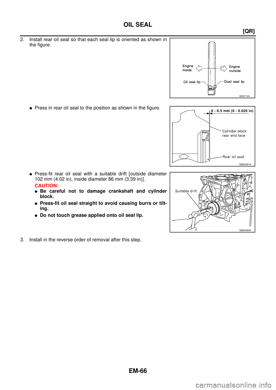
2. Install rear oil seal so that each seal lip is oriented as shown in
the figure.
�Press in rear oil seal to the position as shown in the figure.
�Press-fit rear oil seal with a suitable drift [outside diameter
102 mm (4.02 in), inside diameter 86 mm (3.39 in)].
CAUTION:
�Be careful not to damage crankshaft and cylinder
block.
�Press-fit oil seal straight to avoid causing burrs or tilt-
ing.
�Do not touch grease applied onto oil seal lip.
3. Install in the reverse order of removal after this step.
SEM715A
SBIA0281E
SBIA0280E
Page 120 of 4179
![NISSAN X-TRAIL 2003 Service Repair Manual EM-68
[QR]
CYLINDER HEAD
–If the compression pressure remains at low level despite the addition of engine oil, valves may be mal-
functioning. Check valves for damage. Replace valve or valve seat](/manual-img/5/57404/w960_57404-119.png "NISSAN X-TRAIL 2003 Service Repair Manual EM-68
[QR]
CYLINDER HEAD
–If the compression pressure remains at low level despite the addition of engine oil, valves may be mal-
functioning. Check valves for damage. Replace valve or valve seat")
EM-68
[QR]
CYLINDER HEAD
–If the compression pressure remains at low level despite the addition of engine oil, valves may be mal-
functioning. Check valves for damage. Replace valve or valve seat accordingly.
�If two adjacent cylinders have respectively low compression pressure and their compression remains
low even after the addition of engine oil, gaskets are leaking. In such a case, replace cylinder head gas-
kets.
7. After inspection is completed, install removed parts.
8. Start engine, and confirm that engine runs smoothly.
9. Perform trouble diagnosis. If DTC appears, erase it. Refer to EC-73, "
TROUBLE DIAGNOSIS" (WITH
EURO-OBD) or EC-520, "
TROUBLE DIAGNOSIS" (WITHOUT EURO-OBD).
Removal and InstallationEBS00KNQ
REMOVAL
1. Release fuel pressure. Refer to EC-48, "FUEL PRESSURE RELEASE" (WITH EURO-OBD) or EC-510,
"FUEL PRESSURE RELEASE" (WITHOUT EURO-OBD).
2. Drain engine coolant and engine oil. Refer to CO-9, "
Changing Engine Coolant" and LU-8, "Changing
Engine Oil" .
3. Remove the following components and related parts.
�Exhaust manifold and three way catalyst assembly; Refer to EM-23, "EXHAUST MANIFOLD AND
THREE WAY CATALYST" .
�Intake manifold and fuel tube assembly (QR20DE); Refer to EM-17, "Removal and Installation
(QR20DE)" .
�Intake manifold collector, intake manifold and fuel tube assembly (QR25DE); Refer to EM-20, "Removal
and Installation (QR25DE)" .
�Water control valve and housing (water outlet); Refer to CO-22, "THERMOSTAT AND WATER CON-
TROL VALVE" .
NOTE:
Can be removed and installed even when assembled with cylinder head.
4. Remove front cover and timing chain. Refer to EM-44, "
TIMING CHAIN" .
5. Remove camshafts. Refer to EM-53, "
CAMSHAFT" .
6. Securely support bottom of cylinder block with a jack or equivalent tool, and release the hoist that was
supporting it.
1. Cylinder head assembly 2. Cylinder head gasket 3. Cylinder head bolt
PBIC2185E
Page 121 of 4179
![NISSAN X-TRAIL 2003 Service Repair Manual CYLINDER HEAD
EM-69
[QR]
C
D
E
F
G
H
I
J
K
L
MA
EM
7. Remove cylinder head loosening bolts in reverse order as
shown in the figure.
�Using the following tool, loosen cylinder head bolts.
NOTE:
Ther](/manual-img/5/57404/w960_57404-120.png "NISSAN X-TRAIL 2003 Service Repair Manual CYLINDER HEAD
EM-69
[QR]
C
D
E
F
G
H
I
J
K
L
MA
EM
7. Remove cylinder head loosening bolts in reverse order as
shown in the figure.
�Using the following tool, loosen cylinder head bolts.
NOTE:
Ther")
CYLINDER HEAD
EM-69
[QR]
C
D
E
F
G
H
I
J
K
L
MA
EM
7. Remove cylinder head loosening bolts in reverse order as
shown in the figure.
�Using the following tool, loosen cylinder head bolts.
NOTE:
There are two types of cylinder head bolt because of parallel
manufacture.
8. Remove cylinder head gasket.
INSPECTION AFTER REMOVAL
Cylinder Head Bolts Outer Diameter
�Cylinder head bolts are tightened by plastic zone tightening
method. Whenever the size difference between “d1” and “d2”
exceeds the limit, replace them with a new one.
�If reduction of outer diameter appears in a position other than
“d2”, use it as “d2” point.
NOTE:
When replacing any cylinder head bolts, it is possible to use them
with mixing flange bolt and bolt with washer.
Cylinder Head Distortion
NOTE:
When performing this inspection, cylinder block distortion should be also checking. Refer to EM-102, "
CYLIN-
DER BLOCK DISTORTION" .
1. Wipe off engine oil and remove water scale (like deposit), gasket, sealant, carbon, etc. with a scraper.
CAUTION:
Use utmost care not to allow gasket debris to enter passages for engine oil or water.
2. At each of several locations on bottom surface of cylinder head,
measure the distortion in six directions.
�If it exceeds the limit, replace cylinder head.
INSTALLATION
1. Install cylinder head gasket.Bolt with washer
:Hexagonal wrench [size 10 mm (0.39 in)]
Flange bolt
:TORX socket (size E20)
KBIA0058E
Limit (“d1” – “d2”): 0.23 mm (0.0091 in)
SBIA0269E
Limit: 0.1 mm (0.004 in)
PBIC0075E
Page 122 of 4179
![NISSAN X-TRAIL 2003 Service Repair Manual EM-70
[QR]
CYLINDER HEAD
2. Tighten cylinder head bolts in numerical order as shown in figure
with the following procedure, and install cylinder head.
CAUTION:
If cylinder head bolts are re-used, ch](/manual-img/5/57404/w960_57404-121.png "NISSAN X-TRAIL 2003 Service Repair Manual EM-70
[QR]
CYLINDER HEAD
2. Tighten cylinder head bolts in numerical order as shown in figure
with the following procedure, and install cylinder head.
CAUTION:
If cylinder head bolts are re-used, ch")
EM-70
[QR]
CYLINDER HEAD
2. Tighten cylinder head bolts in numerical order as shown in figure
with the following procedure, and install cylinder head.
CAUTION:
If cylinder head bolts are re-used, check their outer diame-
ters before installation. Refer to EM-69, "
Cylinder Head
Bolts Outer Diameter" .
a. Apply new engine oil to threads and seating surface of mounting
bolts.
b. Tighten all bolts.
c. Turn all bolts 60 degrees clockwise (angle tightening).
d. Completely loosen.
CAUTION:
In this step, loosen bolts in reverse order of that indicated in the figure.
e. Tighten all bolts.
f. Turn all bolts 75 degrees clockwise (angle tightening).
g. Turn all bolts 75 degrees clockwise again (angle tightening).
CAUTION:
Check and confirm the tightening angle by using an angle
wrench (special service tool) or protractor. Avoid judgment
by visual inspection without the tool.
3. Install in the reverse order of removal after this step. : 5.0 N·m (0.51 kg-m, 4 ft-lb)
: 0 N·m (0 kg-m, 0 ft-lb)
: 39.2 N·m (4.0 kg-m, 29 ft-lb)
KBIA0058E
KBIA0059E
Page 134 of 4179
EM-82
[QR]
CYLINDER BLOCK
CYLINDER BLOCKPFP:11010
Disassembly and AssemblyEBS00KNU
1. Cylinder block 2. O-ring 3. Crankshaft position sensor (POS)
4. Knock sensor 5. Water drain plug 6. Lower cylinder block
7. Lower cylinder block mounting bolt 8. Snap ring 9. Connecting rod
10. Connecting rod bearing 11. Connecting rod bearing cap 12. Connecting rod bolt
13. Piston 14. Oil ring 15. Second ring
16. Top ring 17. Piston pin 18. Thrust bearing
19. Main bearing upper 20. Crankshaft 21. Crankshaft key
22. Main bearing lower 23. Rear oil seal 24. Pilot convertor (A/T models)
25. Signal plate 26. Drive plate (A/T models) 27. Reinforce plate (A/T models)
28. Flywheel (M/T models)
PBIC2189E
Page 135 of 4179
CYLINDER BLOCK
EM-83
[QR]
C
D
E
F
G
H
I
J
K
L
MA
EM
DISASSEMBLY
1. Remove engine, transaxle and transfer assembly from vehicle, and separate transaxle and transfer
assembly from engine. Refer to EM-78, "
ENGINE ASSEMBLY" .
2. Mount engine on an engine stand with the following procedure:
a. Remove oil cooler with oil cooler bracket on right side of cylinder block. Refer to LU-11, "
OIL COOLER" .
b. Install engine sub-attachment (special service tool) to right side
of cylinder block.
�Do not use bolt hole at the upper right looking from bolt inser-
tion side as shown in the figure.
�Machine a bolt hole at the lower right of the engine sub-
attachment looking from bolt insertion side as shown in the
figure.
c. Lift engine, and mount it onto the engine stand (special service
tool).
PBIC2190E
SBIA0272E
KBIA0140E
Page 136 of 4179
![NISSAN X-TRAIL 2003 Service Repair Manual EM-84
[QR]
CYLINDER BLOCK
�A widely use engine stand can be used.
NOTE:
This example is an engine stand for holding at transaxle
mounting side with flywheel (M/T models) or drive plate (A/T
models)](/manual-img/5/57404/w960_57404-135.png "NISSAN X-TRAIL 2003 Service Repair Manual EM-84
[QR]
CYLINDER BLOCK
�A widely use engine stand can be used.
NOTE:
This example is an engine stand for holding at transaxle
mounting side with flywheel (M/T models) or drive plate (A/T
models)")
EM-84
[QR]
CYLINDER BLOCK
�A widely use engine stand can be used.
NOTE:
This example is an engine stand for holding at transaxle
mounting side with flywheel (M/T models) or drive plate (A/T
models) removed.
3. Drain engine oil. Refer to LU-8, "
Changing Engine Oil" .
4. Drain engine coolant by removing water drain plug from inside of
engine.
5. Remove cylinder head. Refer to EM-67, "
CYLINDER HEAD" .
6. Remove knock sensor.
CAUTION:
Carefully handle knock sensor avoiding shocks.
7. Remove crankshaft position sensor (POS).
CAUTION:
�Avoid impacts such as a dropping.
�Do not disassemble.
�Keep it away from metal particles.
�Do not place sensor in a location where it is exposed to
magnetism.
8. Remove clutch cover and clutch disc (M/T models). Refer to CL-14, "
CLUTCH DISC, CLUTCH COVER
AND FLYWHEEL" .
9. Remove flywheel (M/T models) or drive plate (A/T models).
�Secure crankshaft with a stopper plate, and remove mounting
bolts.
�Using the following TORX socket, loosen mounting bolts.
CAUTION:
Be careful not to damage contact surface for clutch disc of
flywheel (M/T models).
PBIC0085E
PBIC2443E
PBIC2191E
Flywheel (M/T models)
: size T55 (commercial service tool)
Drive plate (A/T models)
: size E20
PBIC2352E
Page 137 of 4179
![NISSAN X-TRAIL 2003 Service Repair Manual CYLINDER BLOCK
EM-85
[QR]
C
D
E
F
G
H
I
J
K
L
MA
EM
NOTE:
The flywheel, two block construction, allows movement in response to transaxle side pressure, or when
twisted in its rotational direction. T](/manual-img/5/57404/w960_57404-136.png "NISSAN X-TRAIL 2003 Service Repair Manual CYLINDER BLOCK
EM-85
[QR]
C
D
E
F
G
H
I
J
K
L
MA
EM
NOTE:
The flywheel, two block construction, allows movement in response to transaxle side pressure, or when
twisted in its rotational direction. T")
CYLINDER BLOCK
EM-85
[QR]
C
D
E
F
G
H
I
J
K
L
MA
EM
NOTE:
The flywheel, two block construction, allows movement in response to transaxle side pressure, or when
twisted in its rotational direction. Therefore, some amount of noise is normal.
10. Remove pilot converter using pilot bushing puller (special ser-
vice tool) or suitable tool. (A/T models)
NOTE:
M/T models have no pilot bushing.
11. Remove piston and connecting rod assembly with the following procedure:
�Before removing piston and connecting rod assembly, check the connecting rod side clearance. Refer
to EM-99, "
CONNECTING ROD SIDE CLEARANCE" .
a. Position crankshaft pin corresponding to connecting rod to be removed onto the bottom dead center.
b. Remove connecting rod cap.
c. Using a hammer handle or similar tool, push piston and connect-
ing rod assembly out to the cylinder head side.
12. Remove connecting rod bearings.
CAUTION:
When removing them, note the installation position. Keep them in the correct order.
13. Remove piston rings form piston.
�Use a piston ring expander (commercial service tool).
CAUTION:
�When removing piston rings, be careful not to damage
the piston.
�Be careful not to damage piston rings by expanding
them excessively.
14. Remove piston from connecting rod with the following procedure:
SBIA0274E
PBIC0259E
PBIC0087E
![NISSAN X-TRAIL 2003 Service Repair Manual EM-82
[QR]
CYLINDER BLOCK
CYLINDER BLOCKPFP:11010
Disassembly and AssemblyEBS00KNU
1. Cylinder block 2. O-ring 3. Crankshaft position sensor (POS)
4. Knock sensor 5. Water drain plug 6. Lower cylind](/manual-img/5/57404/w960_57404-133.png "NISSAN X-TRAIL 2003 Service Repair Manual EM-82
[QR]
CYLINDER BLOCK
CYLINDER BLOCKPFP:11010
Disassembly and AssemblyEBS00KNU
1. Cylinder block 2. O-ring 3. Crankshaft position sensor (POS)
4. Knock sensor 5. Water drain plug 6. Lower cylind")
![NISSAN X-TRAIL 2003 Service Repair Manual CYLINDER BLOCK
EM-83
[QR]
C
D
E
F
G
H
I
J
K
L
MA
EM
DISASSEMBLY
1. Remove engine, transaxle and transfer assembly from vehicle, and separate transaxle and transfer
assembly from engine. Refer to EM-](/manual-img/5/57404/w960_57404-134.png "NISSAN X-TRAIL 2003 Service Repair Manual CYLINDER BLOCK
EM-83
[QR]
C
D
E
F
G
H
I
J
K
L
MA
EM
DISASSEMBLY
1. Remove engine, transaxle and transfer assembly from vehicle, and separate transaxle and transfer
assembly from engine. Refer to EM-")