Page 3491 of 4179
TROUBLE DIAGNOSIS
ATC-95
C
D
E
F
G
H
I
K
L
MA
B
AT C
Dual-Pressure Switch (With Diesel Engine)
Thermal Protector (With diesel engine)
Check continuity between compressor harness terminal and field
coil.
RJIA2954E
Compressor: ON
kPa (bar, kg/cm2 , psi)Compressor: OFF
kPa (bar, kg/cm2 , psi)
Low-pressure side 186 (1.86, 1.9, 27) 177 (1.77, 1.8, 26)
High-pressure side 1,569 (15.7, 16, 228) 2,746 (27.5, 28, 398)
RJIA0691E
RHA671H
Page 3528 of 4179
ATC-132
HEATER & COOLING UNIT ASSEMBLY
9. Remove steering member.
10. Remove heater & cooling unit.
CAUTION:
Cap or wrap the joint of the pipe with suitable material such as vinyl tape to avoid the entry of air.
INSTALLATION
Installation is basically the reverse order of removal.
CAUTION:
�Replace the O-ring of the low-pressure flexible hose and the high-pressure pipe with a new one,
and then apply compressor oil to it when installing it.
�When recharging refrigerant, check for leaks.
NOTE:
When filling radiator with coolant, refer to CO-9, "
Changing Engine Coolant" for QR engine or CO-31, "Chang-
ing Engine Coolant" for YD engine.
Disassembly and AssemblyEJS000UU
NOTE:
This illustration is for RHD models. The layout for LHD models is symmetrically opposite.
RJIA2404E
Page 3542 of 4179
ATC-146
REFRIGERANT LINES
6. Remove mounting bolts from compressor.
7. Remove compressor from the lower side of the vehicle.
INSTALLATION
Installation is basically the reverse order of removal.
CAUTION:
�Replace the O-ring of low-pressure flexible hose and high-pressure flexible hose with a new one,
then apply compressor oil to it when installing it.
�When recharging refrigerant, check for leaks.
Removal and Installation of Compressor ClutchEJS000VA
REMOVAL
Overhaul (With Gasoline Engine: CWV-615M Compressor)
1. When removing center bolt, hold clutch disc with wrench.
RJIA0021E
RJIA0580E
RHA136E
Page 3544 of 4179
ATC-148
REFRIGERANT LINES
5. Remove field coil harness clip using a pair of pliers.
6. Remove snap ring using external snap ring pliers.
Overhaul (With Diesel Engine: DKV-11G Compressor)
1. Remove two screws holding connector bracket, thermal protec-
tor to compressor.
2. When removing center bolt, hold clutch disc with clutch disc
wrench.
RHA125F
RHA145E
RHA669H
SHA097EA
Page 3546 of 4179
ATC-150
REFRIGERANT LINES
Inspection
Clutch disc
If the contact surface shows signs of damage due to excessive heat,
replace clutch disc and pulley.
Pulley
Check the appearance of the pulley assembly. If contact surface of
pulley shows signs of excessive grooving, replace clutch disc and
pulley. The contact surfaces of the pulley assembly should be
cleaned with a suitable solvent before reinstallation.
Coil
Check coil for loose connection or cracked insulation.
INSTALLATION
With Gasoline Engine (CWV-615M Compressor)
1. Install field coil.
Be sure to align the coil's pin with the hole in the compressor’s
front head.
2. Install field coil harness clip using a screwdriver.
3. Install pulley assembly using installer and a hand press, and
then install snap ring using snap ring pliers.
RJIA0582E
RJIA0583E
RHA142E
RHA143E
Page 3547 of 4179
REFRIGERANT LINES
ATC-151
C
D
E
F
G
H
I
K
L
MA
B
AT C
4. Install clutch disc on drive shaft, together with original shim(s).
Press clutch disc down by hand.
5. Using the holder to prevent clutch disc rotation.
After tightening the bolt, check that the pulley rotates smoothly.
6. Check clearance around the entire periphery of clutch disc.
If the specified clearance is not obtained, replace adjusting
spacer and readjust.
With Diesel Engine (DKV-11G Compressor)
1. Install field coil.
Be sure to align the coil’s pin with the hole in the compressor’s
front head.
2. Install field coil harness clip using a screwdriver.
RHA127F
Tightening torque : 14 N·m (1.4 kg-m, 10 ft-lb)
RHA086E
Disc to pulley clear-
ance: 0.3 - 0.6 mm (0.012 - 0.024 in)
RHA087E
RHA076C
Page 3551 of 4179

REFRIGERANT LINES
ATC-155
C
D
E
F
G
H
I
K
L
MA
B
AT C
INSTALLATION
Installation is basically the reverse order of removal.
CAUTION:
�Replace the O-ring of high-pressure flexible hose with a new one, then apply compressor oil to it
when installing it.
�When recharging refrigerant, check for leaks.
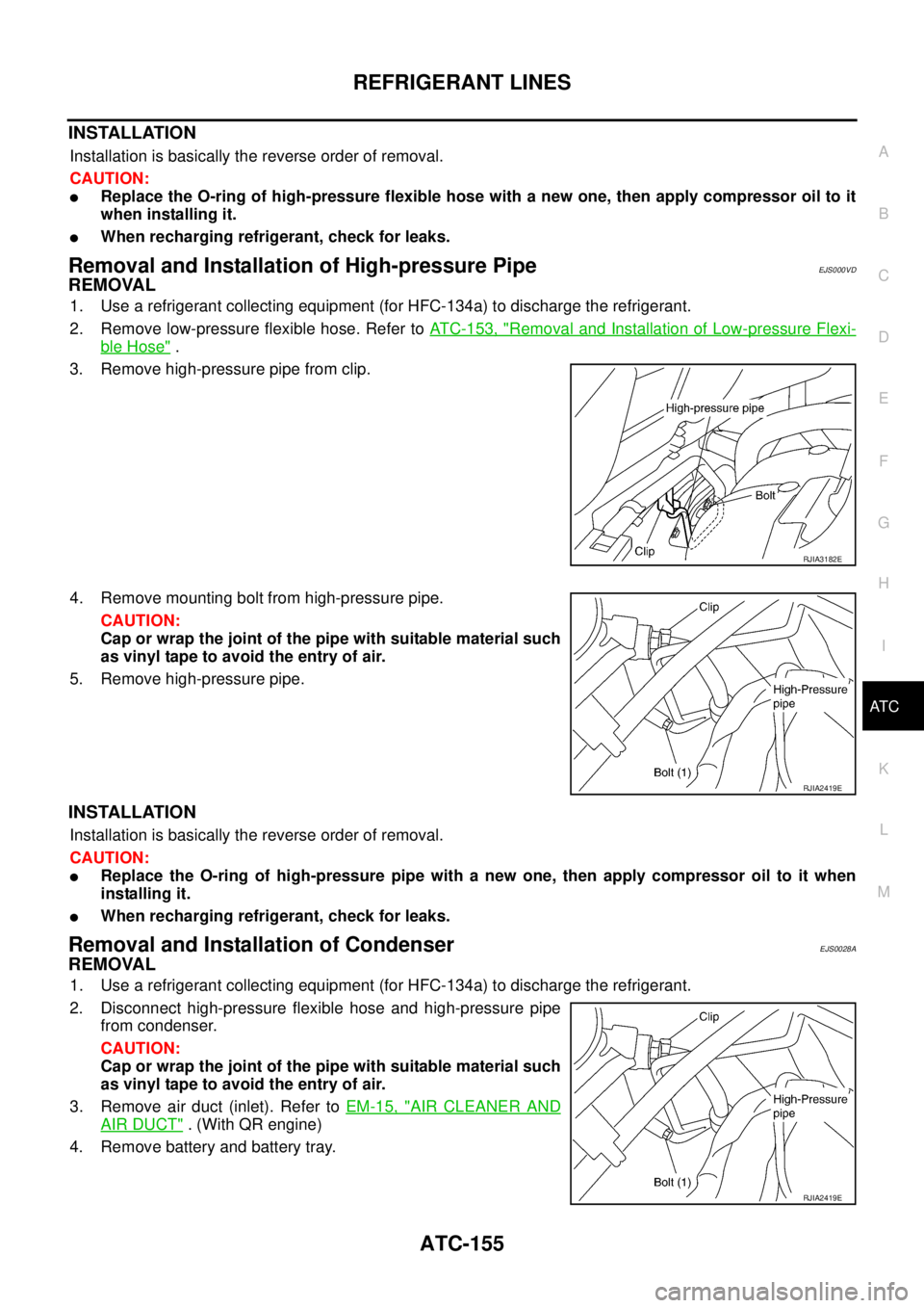
Removal and Installation of High-pressure PipeEJS000VD
REMOVAL
1. Use a refrigerant collecting equipment (for HFC-134a) to discharge the refrigerant.
2. Remove low-pressure flexible hose. Refer to ATC-153, "
Removal and Installation of Low-pressure Flexi-
ble Hose" .
3. Remove high-pressure pipe from clip.
4. Remove mounting bolt from high-pressure pipe.
CAUTION:
Cap or wrap the joint of the pipe with suitable material such
as vinyl tape to avoid the entry of air.
5. Remove high-pressure pipe.
INSTALLATION
Installation is basically the reverse order of removal.
CAUTION:
�Replace the O-ring of high-pressure pipe with a new one, then apply compressor oil to it when
installing it.
�When recharging refrigerant, check for leaks.
Removal and Installation of CondenserEJS0028A
REMOVAL
1. Use a refrigerant collecting equipment (for HFC-134a) to discharge the refrigerant.
2. Disconnect high-pressure flexible hose and high-pressure pipe
from condenser.
CAUTION:
Cap or wrap the joint of the pipe with suitable material such
as vinyl tape to avoid the entry of air.
3. Remove air duct (inlet). Refer to EM-15, "
AIR CLEANER AND
AIR DUCT" . (With QR engine)
4. Remove battery and battery tray.
RJIA3182E
RJIA2419E
RJIA2419E
Page 3552 of 4179

ATC-156
REFRIGERANT LINES
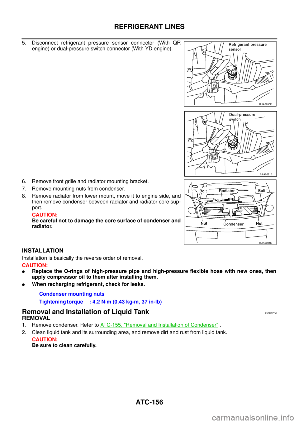
5. Disconnect refrigerant pressure sensor connector (With QR
engine) or dual-pressure switch connector (With YD engine).
6. Remove front grille and radiator mounting bracket.
7. Remove mounting nuts from condenser.
8. Remove radiator from lower mount, move it to engine side, and
then remove condenser between radiator and radiator core sup-
port.
CAUTION:
Be careful not to damage the core surface of condenser and
radiator.
INSTALLATION
Installation is basically the reverse order of removal.
CAUTION:
�Replace the O-rings of high-pressure pipe and high-pressure flexible hose with new ones, then
apply compressor oil to them after installing them.
�When recharging refrigerant, check for leaks.
Removal and Installation of Liquid TankEJS0028C
REMOVAL
1. Remove condenser. Refer to ATC-155, "Removal and Installation of Condenser" .
2. Clean liquid tank and its surrounding area, and remove dirt and rust from liquid tank.
CAUTION:
Be sure to clean carefully.
RJIA0690E
RJIA0691E
RJIA0081E
Condenser mounting nuts
Tightening torque : 4.2 N·m (0.43 kg-m, 37 in-lb)