Page 3671 of 4179
STARTING SYSTEM
SC-27
C
D
E
F
G
H
I
J
L
MA
B
SC
A/T Models
1. Pinion stopper clip 2. Pinion stopper 3. Pinion
4. Pinion spring 5. Gear case assembly 6. Shift lever set
7. Dust cover kit 8. Magnetic switch assembly 9. Clutch assembly
10. E-ring 11. Thrust washer 12. Center bracket (P)
13. Packing 14. Planetary gear 15. Internal gear
16. Center bracket (A) 17. Yoke assembly 18. Armature assembly
19. Brush holder assembly 20. Brush (-) 21. Brush spring
22. Thrust washer 23. Rear cover assembly
Through-bolt:
: 4.9 - 6.4 N·m (0.50 - 0.65 kg-m, 43.4 - 56.4 in-lb)
PKIA0466E
Page 3672 of 4179
SC-28
STARTING SYSTEM
YD ENGINE MODELS
1. Stopper clip 2. Pinion stopper 3. Pinion
4. Spring 5. Gear case 6. Plate
7. Packing 8. Adjusting plate 9. Magnetic switch assembly
10. Snap ring 11. Retainer ring 12. Over running clutch
13. Internal gear 14. Planetary gear 15. Ball
16. Packing 17. Cover 18. Yoke
19. Armature 20. Washer 21. Rear bearing
22. Brush holder assembly 23. Brush spring 24. Brush (-)
25. Rear cover
Through-bolt:
: 5.6 - 10.4 N·m (0.57 - 1.06 kg-m, 49.5 - 92.0 in-lb)
PKIA0465E
Page 3676 of 4179
SC-32
STARTING SYSTEM
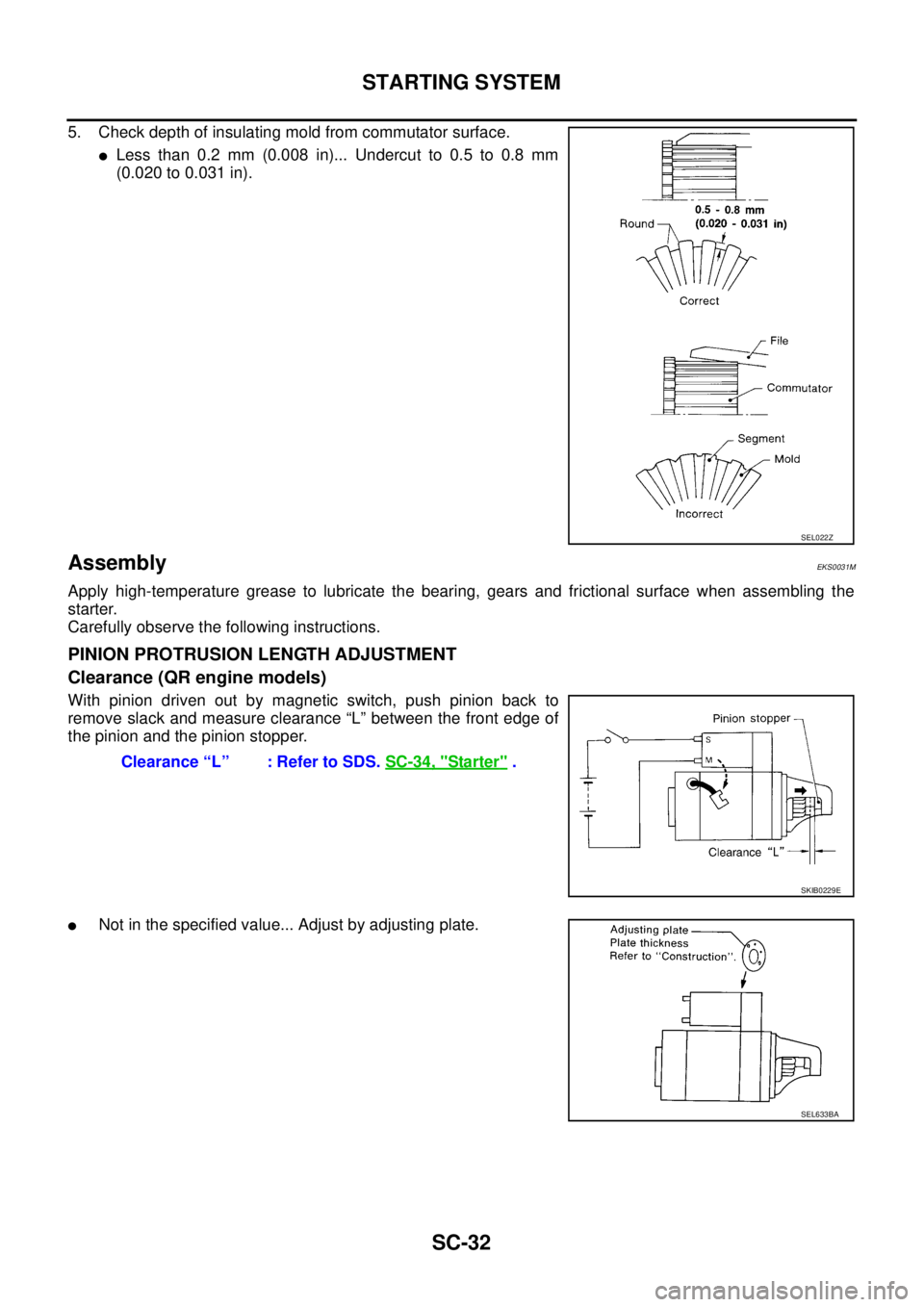
5. Check depth of insulating mold from commutator surface.
�Less than 0.2 mm (0.008 in)... Undercut to 0.5 to 0.8 mm
(0.020 to 0.031 in).
AssemblyEKS0031M
Apply high-temperature grease to lubricate the bearing, gears and frictional surface when assembling the
starter.
Carefully observe the following instructions.
PINION PROTRUSION LENGTH ADJUSTMENT
Clearance (QR engine models)
With pinion driven out by magnetic switch, push pinion back to
remove slack and measure clearance “L” between the front edge of
the pinion and the pinion stopper.
�Not in the specified value... Adjust by adjusting plate.
SEL022Z
Clearance “L” : Refer to SDS. SC-34, "Starter" .
SKIB0229E
SEL633BA
Page 3677 of 4179
STARTING SYSTEM
SC-33
C
D
E
F
G
H
I
J
L
MA
B
SC
Movement (YD engine models)
Compare movement “L” in height of pinion when it is pushed out with
magnetic switch energized and when it is pulled out by hand until it
touches stopper.
�Not in the specified value...Adjust by adjusting plate.Movement “L” : Refer to SDS. SC-34, "
Starter" .
SKIB0230E
SEL633BA
Page 3678 of 4179

SERVICE DATA AND SPECIFICATIONS (SDS)PFP:00030
BatteryEKS0031Q
StarterEKS0031R
AlternatorEKS0031S
Applied modelQR20, QR25 engine
YD22 engine
Except
for N")
SC-34
SERVICE DATA AND SPECIFICATIONS (SDS)
SERVICE DATA AND SPECIFICATIONS (SDS)PFP:00030
BatteryEKS0031Q
StarterEKS0031R
AlternatorEKS0031S
Applied modelQR20, QR25 engine
YD22 engine
Except
for Northern EuropeFor Northern
Europe
Type 55D23L 80D23L 110D26L
Capacity [V - AH] 12-48 12-52 12-64
Applied modelQR20, QR25 engine
YD22 engine
A/T M/T
Ty p eS114-844 M0T87081 M8T71471
HITACHI make MITSUBISHI make
Reduction
System voltage [V] 12
No-loadTerminal voltage [V] 11.0
Current [A] Less than 90 Less than 90 Less than 145
Revolution [rpm] More than 2,700 More than 2,500 More than 3,300
Minimum diameter of commutator [mm (in)] 28.0 (1.102) 28.8 (1.134) 31.4 (1.236)
Minimum length of brush [mm (in)] 10.5 (0.413) 7.0 (0.276) 11.0 (0.433)
Brush spring tension [N (kg, lb)] 16.2 (1.65, 3.64)15.0 - 20.4
(1.5 - 2.1, 3.4 - 4.6)26.7 - 36.1
(2.7 - 3.7, 6.0 - 8.2)
Clearance between bearing metal and armature shaft [mm (in)] Less than 0.2 (0.008) —
Clearance “L” between pinion front edge and pinion
stopper[mm (in)]0.3 - 2.5
(0.012 - 0.098)0.5 - 2.0
(0.020 - 0.079)—
Movement “L” in height of pinion assembly [mm (in)] —0.5 - 2.0
(0.020 - 0.079)
Applied model QR20, QR25 engine YD22 engine
Ty p eLR1110-713 A3TB0771
HITACHI make MITSUBISHI make
Nominal rating [V - A] 12-110 12-90
Ground polarityNegative
Minimum revolutions under no-load
(When 13.5 V is applied)[rpm] Less than 1,100 Less than 1,300
Hot output current (When 13.5V is applied) [A/rpm](More than 35/1,300)
More than 70/1,800
More than 91/2,500
More than 110/5,000More than 29/1,300
More than 76/2,500
More than 88/5,000
Regulated output voltage [V] 14.1 - 14.7
Minimum length of brush [mm (in)] More than 6.0 (0.236) More than 5.0 (0.197)
Brush spring pressure [N (g, oz)]1.0 - 3.43
(102 - 350, 3.60 - 12.34)4.8 - 6.0
(490 - 610, 17.28 - 21.51)
Slip ring minimum diameter [mm (in)] More than 26.0 (1.024) More than 22.1 (0.870)
Rotor coil resistance at 20 °C (68 °F) [Ω] 2.31 2.1 - 2.5
Page 3744 of 4179

WW-4
FRONT WIPER AND WASHER SYSTEM
FRONT WIPER AND WASHER SYSTEMPFP:28810
System DescriptionEKS0032N
WIPER OPERATION
The wiper switch is controlled by a lever built into the combination switch.
There are three wiper switch positions:
�LO speed
�HI speed
�INT (Intermittent)
With the ignition switch in the ON or START position, power is supplied
�through 20A fuse [No. 6, located in the fuse block (J/B)]
�to front wiper motor terminal 2.
Low and High Speed Wiper Operation
Ground is supplied to front wiper and washer switch terminal 17 through body grounds E24 and E50.
When the wiper switch is placed in the LO position, ground is supplied
�through front wiper and washer switch terminal 14
�to front wiper motor terminal 3.
With power and ground supplied, the wiper motor operates at low speed.
When the wiper switch is placed in the HI position, ground is supplied
�through front wiper and washer switch terminal 16
�to front wiper motor terminal 5.
With power and ground supplied, the wiper motor operates at high speed.
Auto Stop Operation
With wiper switch turned OFF, wiper motor will continue to operate until wiper arms reach windshield base.
When wiper arms are not located at base of windshield with wiper switch OFF, ground is provided
�from front wiper and washer switch terminal 14
�to front wiper motor terminal 3, in order to continue wiper motor operation at low speed.
Ground is also supplied
�through front wiper and washer switch terminal 13
�to front wiper motor terminal 4
�through terminal 1 of the front wiper motor terminal 1 and
�through grounds E24 and E50.
When wiper arms reach base of windshield, front wiper motor terminals 2 and 4 are connected instead of ter-
minals 1 and 4. Wiper motor will then stop wiper arms at the STOP position.
Intermittent Operation
The front wiper motor operates the wiper arms one time at low speed at a set interval of approximately 1 to 13
seconds. This feature is controlled by the wiper amplifier (INT SW) combined with front wiper and washer
switch.
When the wiper switch is placed in the INT position, ground is supplied to wiper amplifier.
The desired interval time is input to wiper amplifier (INT VR) from wiper volume switch combined with front
wiper and washer switch.
Then intermittent ground is supplied
�through wiper amplifier (OUTPUT) and
�through front wiper and washer switch terminal 14
�to front wiper motor terminal 3
The wiper motor operates at low speed at the desired interval.
WASHER OPERATION
With the ignition switch in the ON or START position, power is supplied
�through 20A fuse [No. 6, located in the fuse block (J/B)]
�to front washer motor terminal 1.
When the lever is pulled to the WASH position, ground is supplied
Page 3937 of 4179

NAVIGATION SYSTEM
AV-47
C
D
E
F
G
H
I
J
L
MA
B
AV
Display With Pushed “ROUTE” Switch
�Easy Mode
�Expert Mode
The Function of Each Icon Is as Follows:
*: When destinations have been entered, route guidance has been turned OFF or destination has been reached, “Route Info.” and “Edit
Route” are not displayed.
SKIA1382E
SKIA1383E
IconMODE
Description
Easy Expert
Quick Stop××The selected facility is set as the destination or waypoint.
(Route guidance has been turned OFF or the destination has been reached)
Where am I?××Next, current and previous street names can be displayed.
Route Info.*×The following items can be set.
�Complete Route
�Tu rn List
�Route Simulation
(Displayed only when the destination area has been set.)
Edit Route*×Change the destination or add the transit points of the route set in the route guide. (Dis-
played only when the automatic reroute function has been turned OFF and the recom-
mended route is not followed.)
Route Calculation×This key is used to start the route calculation after all the settings are completed.
Help×Explanation of Navigational functions appear on the Display.
Page 3990 of 4179

AV-100
NAVIGATION SYSTEM
DESTINATION, PASSING POINTS, AND MENU ITEMS CANNOT BE SELECTED/SET.
VOICE GUIDE
Symptom Cause Remedy
Passing point is not searched
when re-searching the route.The vehicle has already passed the passing point,
or the system judged so.To include the passing points that have been
passed into the route again, set the route
again.
Route information will not be dis-
played.Route searching has not been done. Set the destination and perform route
searching.
Vehicle mark is not on the recommended route. Drive on the recommended route.
Route guide is turned OFF. Turn the route guide ON.
Route information is not available on the dark pink
route.System is not malfunction.
After the route searching, no guide
sign will appear as the vehicle
goes near the entrance/exit to the
toll road.Vehicle mark is not on the recommended route.
(On the display, only guide signs related to the
recommended route will be shown.)Drive on the recommended route.
Automatic route searching is not
possible.Vehicle is driving on a highway (gray route), or no
recommended route is available.Drive on a road to be searched. Or re-
search the route manually. In this case, how-
ever, the whole route will be searched.
Performed automatic detour
search (or detour search). How-
ever, the result is the same as that
of the previous search.Performed search with every conditions consid-
ered. However, the result is the same as that of
the previous search.System is not malfunction.
Passing points cannot be set. More than five passing points were set. Passing points can be set up to five. To stop
at more than five points, perform sharing in
several steps.
When setting the route, the start-
ing point cannot be selected.The current vehicle location is always set as the
starting point of a route.System is not malfunction.
Some menu items cannot be
selected.The vehicle is being driven. Stop the vehicle at a safe place and then
operate the system.
Symptom Cause Remedy
Voice guide will not operate. Note: Voice guide is only available at intersections
that satisfy certain conditions (indicated by � on
the map). Therefore, guidance may not be given
even when the route on the map changes direc-
tion.System is not malfunction.
The vehicle is not on the recommended route. Return to the recommended route or re-
search the route.
Voice guide is turned OFF. Turn the voice guide ON.
Route guide is turned OFF. Turn the route guide ON.
Voice guide does not match the
actual road pattern.Voice guide may vary with the direction to which
the vehicle is turn and the connection of the road
to other roads.Drive in conformity to the actual traffic rules.


Compare movement “L” in height of pinion when it is pushed out with
magnetic switch energized and when it is pulled ou")