Page 3558 of 4179
 above 16°C
(61°F). If less than specification, recover/evacuate and recharge")
ATC-162
REFRIGERANT LINES
3. Check if the A/C refrigerant pressure is at least 345 kPa (3.45 bar, 3.52 kg/cm2 , 50 psi) above 16°C
(61°F). If less than specification, recover/evacuate and recharge the system with the specified amount of
refrigerant.
NOTE:
At temperatures below 16°C (61°F), leaks may not be detected since the system may not reach 345 kPa (3.45
bar, 3.52 kg/cm
2 , 50 psi).
4. Perform the leak test from the high-pressure side (compressor discharge a to evaporator inlet g) to the
low-pressure side (evaporator drain hose h to shaft seal k). Refer to ATC-143, "
Components" . Perform a
leak check for the following areas carefully. Clean the component to be checked and move the leak
detected probe completely around the connection/component.
Compressor
Check the fitting of high- and low- pressure hoses, relief valve and shaft seal.
Liquid tank
Check the refrigerant pressure sensor or dual pressure switch.
Service valves
Check all around the service valves. Ensure service valve caps are secured on the service valves (to pre-
vent leaks).
NOTE:
After removing A/C manifold gauge set from service valves, wipe any residue from valves to prevent any
false readings by leak detector.
Cooling unit (Evaporator)
With engine OFF, turn blower fan on “High” for at least 15 seconds to dissipate any refrigerant trace in the
cooling unit. Wait a minimum of 10 minutes accumulation time (refer to the manufacturer’s recommended
procedure for actual wait time) before inserting the leak detector probe into the drain hose.
Keep the probe inserted for at least 10 seconds. Use caution not to contaminate the probe tip with water
or dirt that may be in the drain hose.
5. If a leak detector detects a leak, verify at least once by blowing compressed air into area of suspected
leak, then repeat check as outlined above.
6. Do not stop when one leak is found. Continue to check for additional leaks at all system components.
If no leaks are found, perform steps 7-10.
7. Start engine.
8. Set the heater A/C control as follows;
a. A/C switch: ON
b. Mode control dial: VENT (Ventilation)
c. Intake position: Recirculation
d. Max. cold temperature
e. Fan speed: High
9. Run engine at 1,500 rpm for at least 2 minutes.
10. Turn engine off and perform leak check again following steps 4 through 6 above.
Refrigerant leaks should be checked immediately after stopping the
engine. Begin with the leak detector at the compressor. The pres-
sure on the high-pressure side will gradually drop after refrigerant
circulation stops and pressure on the low-pressure side will gradually
rise, as shown in the graph. Some leaks are more easily detected
when pressure is high.
11. Discharge A/C system using approved refrigerant recovery equipment. Repair the leaking fitting or com-
ponent if necessary.
12. Evacuate and recharge A/C system and perform the leak test to confirm no refrigerant leaks.
SHA839E
Page 3585 of 4179

MA-25
C
D
E
F
G
H
I
J
K
MA
B
MA
Changing Oil FilterELS000ZJ
REMOVAL
1. Open oil filter installation/removal cover on RH undercover.
2. Using an oil filter wrench")
ENGINE MAINTENANCE (QR20DE·QR25DE)
MA-25
C
D
E
F
G
H
I
J
K
MA
B
MA
Changing Oil FilterELS000ZJ
REMOVAL
1. Open oil filter installation/removal cover on RH undercover.
2. Using an oil filter wrench (special service tool), remove oil filter.
CAUTION:
�Oil filter is provided with relief valve. Use Genuine Nissan
Oil Filter or equivalent.
�Be careful not to get burned when engine and engine oil
may be hot.
�When removing, prepare a shop cloth to absorb any
engine oil leakage or spillage.
�Do not allow engine oil to adhere to drive belt.
�Completely wipe off any engine oil that adheres to engine
and vehicle.
INSTALLATION
1. Remove foreign materials adhering to the oil filter installation surface.
2. Apply new engine oil to the oil seal contact surface of new oil fil-
ter.
3. Screw oil filter manually until it touches the installation surface,
then tighten it by 2/3 turn. Or tighten to specification.
INSPECTION AFTER INSTALLATION
1. Start engine, and make sure there is no leaks of engine oil.
2. Stop engine and wait for 10 minutes.
3. Check the engine oil level and add engine oil. Refer to MA-23, "
Changing Engine Oil" .
KBIA0303E
SMA010
Oil filter:
: 17.6 N·m (1.8 kg-m, 13 ft-lb)
SMA229B
Page 3594 of 4179
MA-34
ENGINE MAINTENANCE (YD22DDTI)
�The oil filter is provided with a relief valve.
INSTALLATION
1. Remove foreign materials adhering to the oil filter installation surface.
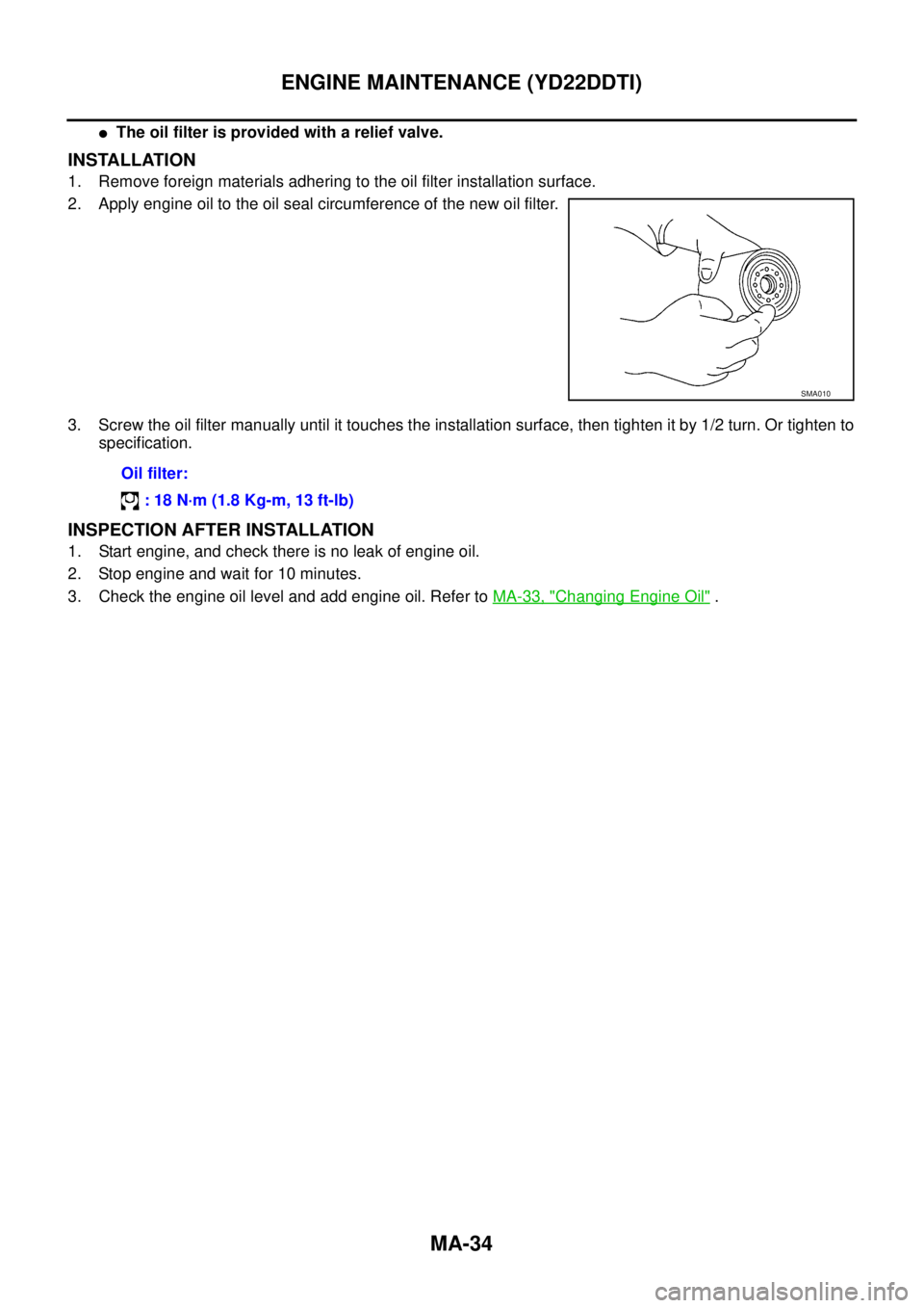
2. Apply engine oil to the oil seal circumference of the new oil filter.
3. Screw the oil filter manually until it touches the installation surface, then tighten it by 1/2 turn. Or tighten to
specification.
INSPECTION AFTER INSTALLATION
1. Start engine, and check there is no leak of engine oil.
2. Stop engine and wait for 10 minutes.
3. Check the engine oil level and add engine oil. Refer to MA-33, "
Changing Engine Oil" .
SMA010
Oil filter:
: 18 N·m (1.8 Kg-m, 13 ft-lb)
Page 3596 of 4179

5. Remove O-ring from oil filter body.
�Push O-ring in one direction, lift the slack part using fingers,
and remove O-ring from oil filter body.
CAUTION:
Do not u")
MA-36
ENGINE MAINTENANCE (YD22DDTI)
5. Remove O-ring from oil filter body.
�Push O-ring in one direction, lift the slack part using fingers,
and remove O-ring from oil filter body.
CAUTION:
Do not use a screwdrivers etc. as they may cause dam-
age to oil filter body.
INSTALLATION
1. Completely remove all foreign objects adhering to the inside of oil filter body or O-ring mounting area
(body side and bracket side).
2. Install oil filter and O-ring to oil filter body.
�Push oil filter into filter body completely.
3. Install oil filter body to oil filter bracket.
INSPECTION AFTER INSTALLATION
1. After warming up engine, check there is no leaks of engine oil.
2. Stop engine and wait for 10 minutes.
3. Check the engine oil level and add engine oil. Refer to MA-33, "
Changing Engine Oil" .
Draining WaterELS000CJ
1. Prepare a tray at the drain hose open end.
2. Loosen drain cock, and operate priming pump to drain water
from fuel filter.
CAUTION:
�Water in filter is drained with fuel. Prepare larger capacity
pan than fuel filter volume.
�Drained water is mixed with fuel. Prevent fuel from adher-
ing to rubber parts such as engine mount insulator.
3. After draining, close drain cock by hand.
CAUTION:
If drain cock is tightened excessively, it may be damaged
and fuel will leak. Do not use tools to tighten drain cock.
4. Bleed air in fuel piping. Refer to FL-18, "
Air Bleeding" .
5. Start engine and make sure there is no fuel leakage.
JLC292B
Oil filter body:
: 22 N·m (2.2 Kg-m, 16 ft-lb)
SBIA0138E
Page 3599 of 4179

CHASSIS AND BODY MAINTENANCE
MA-39
C
D
E
F
G
H
I
J
K
MA
B
MA
6. Check fluid condition.
�If fluid is very dark or smells burned, refer to AT section for
checking operation of A/T. Flush cooling system after repair of
A/T.
�If A/T fluid contains frictional material (clutches, bands, etc.),
replace radiator and flush cooler line using cleaning solvent
and compressed air after repair of A/T. Refer to CO-12,
"RADIATOR" , CO-14, "RADIATOR (ALUMINUM TYPE)" .
7. Install the removed dipstick in the A/T fluid charging pipe.
Changing A/T FluidELS000BW
1. Warm up A/T fluid.
2. Stop engine.
3. Drain A/T fluid from drain plug and refill with new A/T fluid.
Always refill same volume with drained fluid.
4. Run engine at idle speed for five minutes.
5. Check fluid level and condition. Refer to MA-38, "
Checking A/T Fluid" . If fluid is still dirty, repeat steps 2
through 5.
Checking Transfer OilELS000BT
Check for oil leakage and oil level.
CAUTION:
Never start engine while checking oil level.
Changing Transfer OilELS000BU
1. Drain oil from drain plug and refill with new gear oil.
SMA853B
Fluid grade:
Genuine Nissan ATF or equivalent. Refer to MA-
17, "RECOMMENDED FLUIDS AND LUBRI-
CANTS" .
Fluid capacity (With torque converter):
Approx. 8.5 (7-1/2 lmp qt)
Drain plug:
: 34 N·m (3.5 kg-m, 25 ft-lb)
SMA052D
Filler plug:
: 9.8 - 19.6 N·m (1.0 - 1.9 kg-m, 87 - 173 in-lb)
SDIA0513E
Page 3653 of 4179

�Check battery type and determine the specified current using the table shown above.
�After starting")
BATTERY
SC-9
C
D
E
F
G
H
I
J
L
MA
B
SC
Fig. 4 INITIAL CHARGING CURRENT SETTING (Standard charge)
�Check battery type and determine the specified current using the table shown above.
�After starting charging, adjustment of charging current is not necessary.
Fig. 5 ADDITIONAL CHARGE (Standard charge)
CAUTION:
�Do not use standard charge method on a battery whose specific gravity is less than 1.100.
�Set charging current to specified value in Fig. 4. If charger is not capable of producing specified
current value, set its charging current as close to that value as possible.
�Keep battery away from open flame while it is being charged.
�When connecting charger, connect leads first, then turn on charger. Do not turn on charger first,
as this may cause a spark.
�If battery temperature rises above 55 °C (131 °F), stop charging. Always charge battery when its
temperature is below 55 °C (131 °F).
CONVERTED
SPECIFIC
GRAVITYBATTERY TYPE
28B19R(L)
34B19R(L)
46B24R(L)
55B24R(L)
50D23R(L)
55D23R(L)
025 [YUASA type code]
027 [YUASA type code]
65D26R(L)
80D23R(L)
80D26R(L)
067 [YUASA type code]
096 [YUASA type code]
75D31R(L)
95D31R(L)
115D31R(L)
110D26R(L)
95E41R(L)
130E41R(L)
1.100 - 1.130 4.0 (A) 5.0 (A) 6.0 (A) 7.0 (A)8.0
(A)9.0 (A)13.
0
(A)
1.130 - 1.160 3.0 (A) 4.0 (A) 5.0 (A) 6.0 (A)7.0
(A)8.0 (A)11 .
0
(A)
1.160 - 1.190 2.0 (A) 3.0 (A) 4.0 (A) 5.0 (A)6.0
(A)7.0 (A)9.0
(A)
1.190 - 1.220 2.0 (A) 2.0 (A) 3.0 (A) 4.0 (A)5.0
(A)5.0 (A)7.0
(A)
*:SC-6, "CHART II"
SEL759W
Page 3654 of 4179

�Check battery type and determine the specified current using the table shown above.
�After sta")
SC-10
BATTERY
C: QUICK CHARGE
Fig. 6 INITIAL CHARGING CURRENT SETTING AND CHARGING TIME (Quick charge)
�Check battery type and determine the specified current using the table shown above.
�After starting charging, adjustment of charging current is not necessary.
CAUTION:
�Do not use quick charge method on a battery whose specific gravity is less than 1.100.
�Set initial charging current to specified value in Fig. 6. If charger is not capable of producing spec-
ified current value, set its charging current as close to that value as possible.
�Keep battery away from open flame while it is being charged.
�When connecting charger, connect leads first, then turn on charger. Do not turn on charger first,
as this may cause a spark.
�Be careful of a rise in battery temperature because a large current flow is required during quick-
charge operation.
If battery temperature rises above 55 °C (131 °F), stop charging. Always charge battery when its
temperature is below 55 °C (131 °F).
�Do not exceed the charging time specified in Fig. 6, because charging battery over the charging
time can cause deterioration of the battery.
*:SC-6, "CHART II"
SEL760W
BATTERY TYPE
28B19R(L)
34B19R(L)
46B24R(L)
55B24R(L)
50D23R(L)
55D23R(L)
65D26R(L)
80D23R(L)
80D26R(L)
025 [YUASA type code]
027 [YUASA type code]
067 [YUASA type code]
096 [YUASA type code]
75D31R(L)
95D31R(L)
115D31R(L)
110D26R(L)
95E41R(L)
130E41R(L)
CURRENT [A] 10 (A) 15 (A) 20 (A) 25 (A) 30 (A)40
(A)
CONVERTED SPECIFIC GRAVITY
1.100 -
1.1302.5 hours
1.130 -
1.1602.0 hours
1.160 -
1.1901.5 hours
1.190 -
1.2201.0 hours
Above
1.2200.75 hours (45 min.)
Page 3670 of 4179
SC-26
STARTING SYSTEM
Disassembly and Assembly EKS0031K
QR ENGINE MODELS
M/T Models
1. Sleeve bearing 2. Gear case 3. Stopper clip
4. Pinion stopper 5. Pinion assembly 6. Internal gear
7. Plate 8. Packing 9. Adjusting plate
10. Magnetic switch assembly 11. Planetary gear 12. Ball
13. Packing 14. Yoke 15. Armature
16. Brush holder assembly 17. Rear bearing 18. Rear cover
Through-bolt:
: 4.1 - 7.4 N·m (0.45 - 0.72 kg-m, 39.1 - 62.5 in-lb)
PKIA0464E