Page 273 of 4179
CYLINDER BLOCK
EM-221
[YD22DDTi]
C
D
E
F
G
H
I
J
K
L
MA
EM
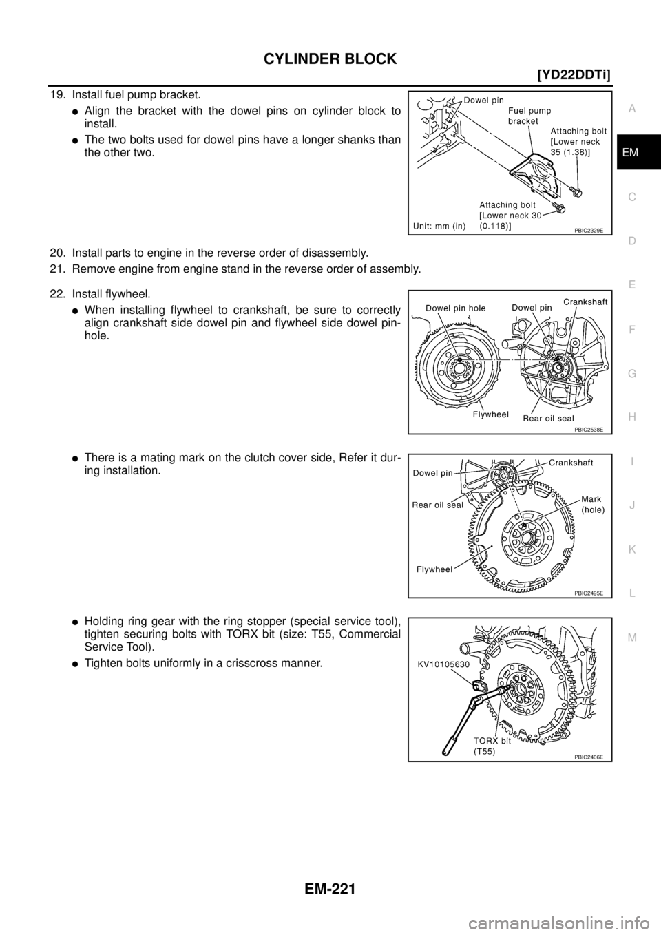
19. Install fuel pump bracket.
�Align the bracket with the dowel pins on cylinder block to
install.
�The two bolts used for dowel pins have a longer shanks than
the other two.
20. Install parts to engine in the reverse order of disassembly.
21. Remove engine from engine stand in the reverse order of assembly.
22. Install flywheel.
�When installing flywheel to crankshaft, be sure to correctly
align crankshaft side dowel pin and flywheel side dowel pin-
hole.
�There is a mating mark on the clutch cover side, Refer it dur-
ing installation.
�Holding ring gear with the ring stopper (special service tool),
tighten securing bolts with TORX bit (size: T55, Commercial
Service Tool).
�Tighten bolts uniformly in a crisscross manner.
PBIC2329E
PBIC2538E
PBIC2495E
PBIC2406E
Page 1928 of 4179
CL-14
CLUTCH DISC, CLUTCH COVER AND FLYWHEEL
CLUTCH DISC, CLUTCH COVER AND FLYWHEELPFP:30100
Removal and InstallationECS008BG
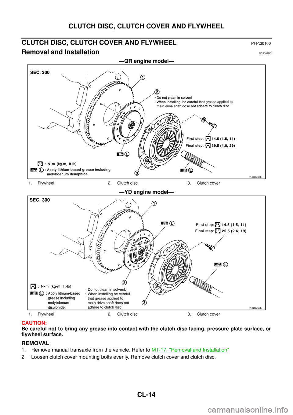
—QR engine model—
—YD engine model—
CAUTION:
Be careful not to bring any grease into contact with the clutch disc facing, pressure plate surface, or
flywheel surface.
REMOVAL
1. Remove manual transaxle from the vehicle. Refer to MT-17, "Removal and Installation"
2. Loosen clutch cover mounting bolts evenly. Remove clutch cover and clutch disc.
PCIB0768E
1. Flywheel 2. Clutch disc 3. Clutch cover
PCIB0769E
1. Flywheel 2. Clutch disc 3. Clutch cover
Page 1930 of 4179
CL-16
CLUTCH DISC, CLUTCH COVER AND FLYWHEEL
INSTALLATION
1. Apply recommended grease to clutch disc and input shaft splines.
CAUTION:
Be sure to apply grease to the points specified. Otherwise, noise, poor disengagement, or damage
to the clutch may result. Excessive grease may cause slip or quiver. Wipe off any grease oozing
from the parts.
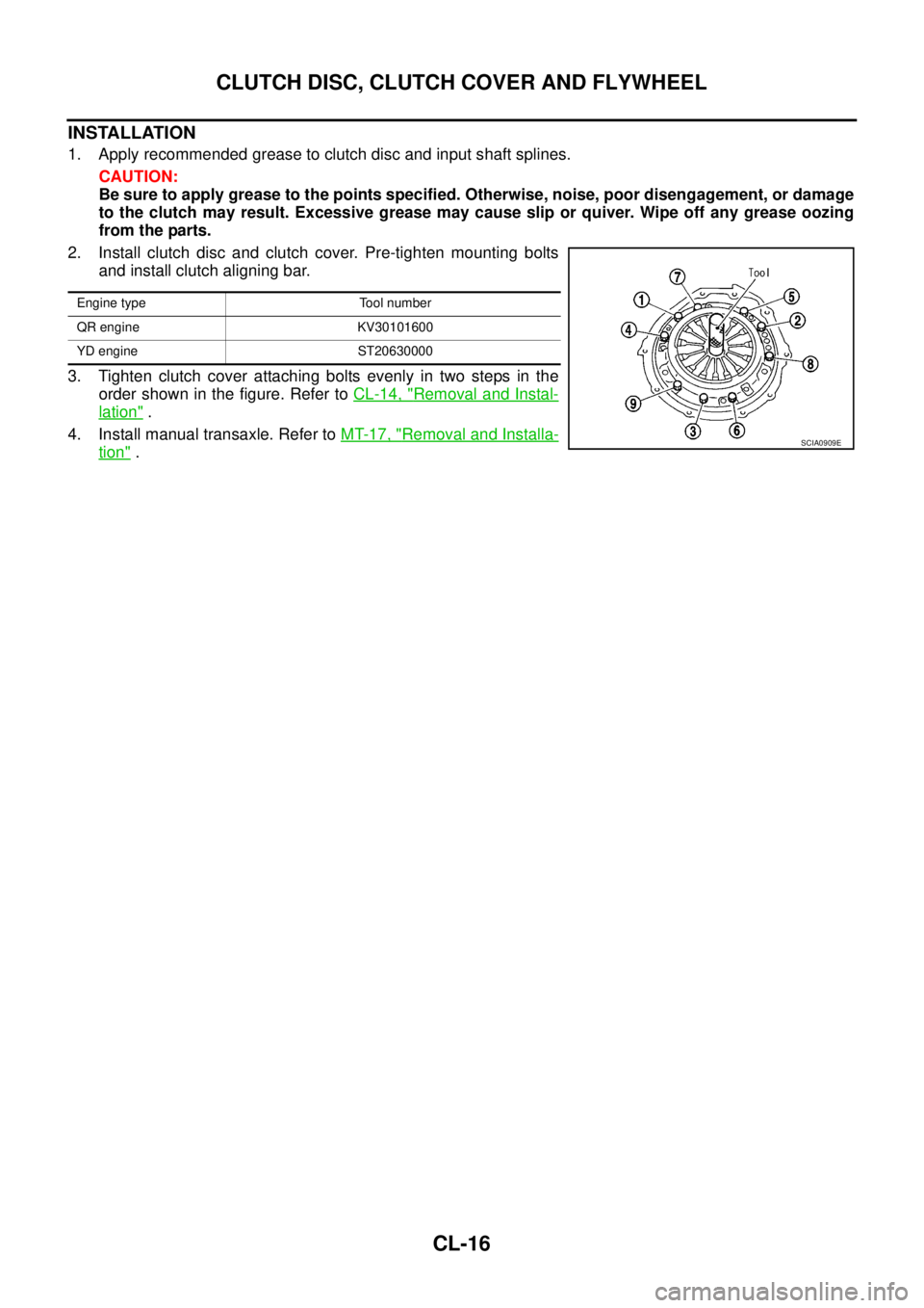
2. Install clutch disc and clutch cover. Pre-tighten mounting bolts
and install clutch aligning bar.
3. Tighten clutch cover attaching bolts evenly in two steps in the
order shown in the figure. Refer to CL-14, "
Removal and Instal-
lation" .
4. Install manual transaxle. Refer to MT-17, "
Removal and Installa-
tion" .
Engine type Tool number
QR engine KV30101600
YD engine ST20630000
SCIA0909E
Page 2104 of 4179
AT-68
[EURO-OBD]
TROUBLE DIAGNOSIS — BASIC INSPECTION
Line Pressure TestECS004QS
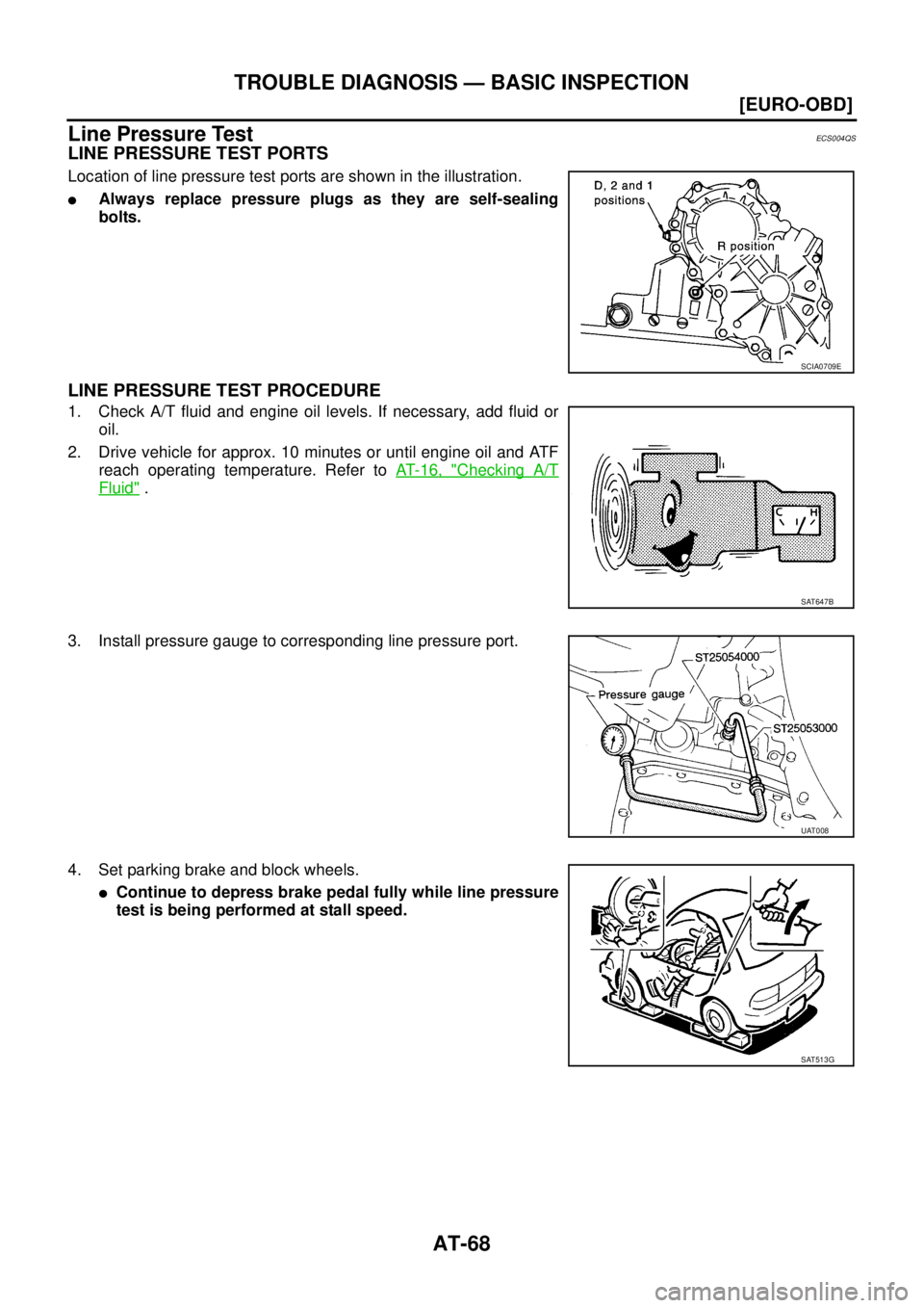
LINE PRESSURE TEST PORTS
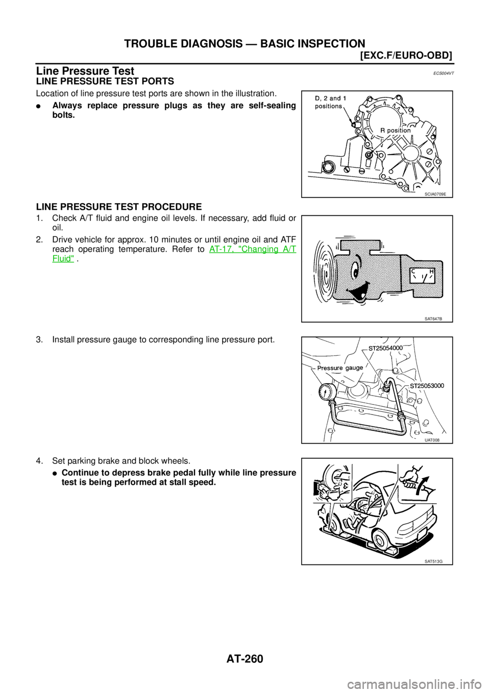
Location of line pressure test ports are shown in the illustration.
�Always replace pressure plugs as they are self-sealing
bolts.
LINE PRESSURE TEST PROCEDURE
1. Check A/T fluid and engine oil levels. If necessary, add fluid or
oil.
2. Drive vehicle for approx. 10 minutes or until engine oil and ATF
reach operating temperature. Refer to AT- 1 6 , "
Checking A/T
Fluid" .
3. Install pressure gauge to corresponding line pressure port.
4. Set parking brake and block wheels.
�Continue to depress brake pedal fully while line pressure
test is being performed at stall speed.
SCIA0709E
SAT647B
UAT008
SAT513G
Page 2296 of 4179
AT-260
[EXC.F/EURO-OBD]
TROUBLE DIAGNOSIS — BASIC INSPECTION
Line Pressure TestECS004VT
LINE PRESSURE TEST PORTS
Location of line pressure test ports are shown in the illustration.
�Always replace pressure plugs as they are self-sealing
bolts.
LINE PRESSURE TEST PROCEDURE
1. Check A/T fluid and engine oil levels. If necessary, add fluid or
oil.
2. Drive vehicle for approx. 10 minutes or until engine oil and ATF
reach operating temperature. Refer to AT- 1 7 , "
Changing A/T
Fluid" .
3. Install pressure gauge to corresponding line pressure port.
4. Set parking brake and block wheels.
�Continue to depress brake pedal fully while line pressure
test is being performed at stall speed.
SCIA0709E
SAT647B
UAT008
SAT513G
Page 2701 of 4179
FRONT WHEEL HUB AND KNUCKLE
FAX-7
C
E
F
G
H
I
J
K
L
MA
B
FA X
FRONT WHEEL HUB AND KNUCKLEPFP:40202
On-Vehicle InspectionEDS0005R
Inspect to check that there is no excessive play, cracking, wear, or
other damage to front axle.
�Turn front wheels (left/right) and check the play.
�Check that no nails or other foreign objects are embedded.
�Retighten all axle nuts and bolts to the specified torque.
FRONT WHEEL BEARINGS
With the vehicle raised, inspect the following.
�Move wheel hub in the axial direction by hand. Check that there is no looseness of front wheel bearings.
�Rotate wheel hub and check that there is no unusual noise or other irregular conditions. If there are any
irregular conditions, replace the wheel bearing.
Removal and InstallationEDS0005S
REMOVAL
1. Remove tyre. Remove brake hose lock plate from strut.
2. Remove brake caliper from steering knuckle. Hang it in a place where it will not interfere with work. Refer
to BR-27, "
FRONT DISC BRAKE" .
CAUTION:
Avoid depressing the brake pedal with brake caliper removed.
3. Remove wheel sensor from steering knuckle. Refer to BRC-116, "
WHEEL SENSORS" .
CAUTION:
Do not pull on wheel sensor harness.
SMA525A
Axial end play : 0.05 mm (0.002 in)
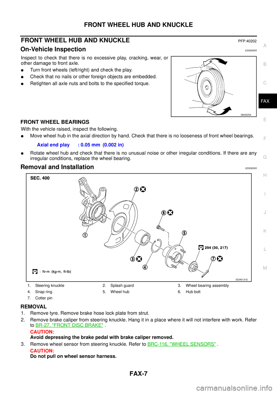
1. Steering knuckle 2. Splash guard 3. Wheel bearing assembly
4. Snap ring 5. Wheel hub 6. Hub bolt
7. Cotter pin
SDIA0131E
Page 2705 of 4179
FRONT DRIVE SHAFT
FAX-11
C
E
F
G
H
I
J
K
L
MA
B
FA X
FRONT DRIVE SHAFTPFP:39100
Removal and InstallationEDS0005U
REMOVAL
1. Remove tyre from vehicle.
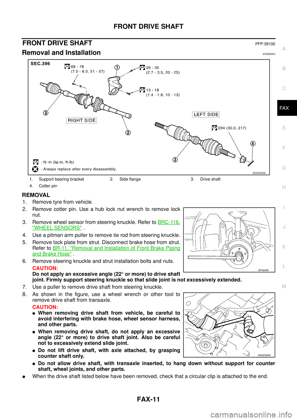
2. Remove cotter pin. Use a hub lock nut wrench to remove lock
nut.
3. Remove wheel sensor from steering knuckle. Refer to BRC-116,
"WHEEL SENSORS" .
4. Use a pitman arm puller to remove tie rod from steering knuckle.
5. Remove lock plate from strut. Disconnect brake hose from strut.
Refer to BR-11, "
Removal and Installation of Front Brake Piping
and Brake Hose" .
6. Remove steering knuckle and strut installation bolts and nuts.
CAUTION:
Do not apply an excessive angle (22° or more) to drive shaft
joint. Firmly support steering knuckle so that slide joint is not excessively extended.
7. Use a puller to remove drive shaft from steering knuckle.
8. As shown in the figure, use a wheel wrench or other tool to
remove drive shaft from transaxle.
CAUTION:
�When removing drive shaft from vehicle, be careful to
avoid interfering with brake hose, wheel sensor harness,
and other parts.
�When removing drive shaft, do not apply an excessive
angle (22° or more) to drive shaft joint. Also be careful
not to excessively extend slide joint.
�Do not lift drive shaft, with axle attached, by grasping
counter shaft only.
�Do not allow drive shaft, with transaxle inserted, to hang down without support for counter
shaft, wheel joints, and other parts.
�When the drive shaft listed below have been removed, check that a circular clip is attached to the end.
1. Support bearing bracket 2. Side flange 3. Drive shaft
4. Cotter pin
SDIA2333E
SFA649A
MAA0384D
Page 2706 of 4179
FAX-12
FRONT DRIVE SHAFT
×: Applicable
–: Not applicable
�Remove installation bolts from right-side drive shaft support bearing bracket. Then remove bracket from
engine.
�Remove installation bolts from right-side drive shaft and remove drive shaft from side shaft.
INSPECTION AFTER REMOVAL
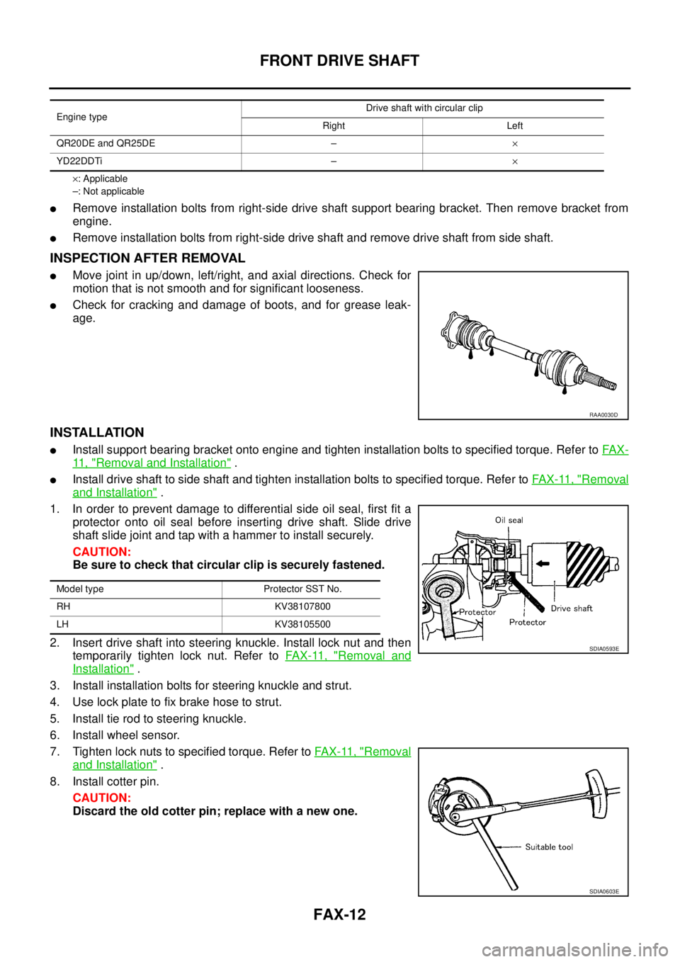
�Move joint in up/down, left/right, and axial directions. Check for
motion that is not smooth and for significant looseness.
�Check for cracking and damage of boots, and for grease leak-
age.
INSTALLATION
�Install support bearing bracket onto engine and tighten installation bolts to specified torque. Refer to FA X -
11 , "Removal and Installation" .
�Install drive shaft to side shaft and tighten installation bolts to specified torque. Refer to FA X - 11 , "Removal
and Installation" .
1. In order to prevent damage to differential side oil seal, first fit a
protector onto oil seal before inserting drive shaft. Slide drive
shaft slide joint and tap with a hammer to install securely.
CAUTION:
Be sure to check that circular clip is securely fastened.
2. Insert drive shaft into steering knuckle. Install lock nut and then
temporarily tighten lock nut. Refer to FA X - 11 , "
Removal and
Installation" .
3. Install installation bolts for steering knuckle and strut.
4. Use lock plate to fix brake hose to strut.
5. Install tie rod to steering knuckle.
6. Install wheel sensor.
7. Tighten lock nuts to specified torque. Refer to FAX-11, "
Removal
and Installation" .
8. Install cotter pin.
CAUTION:
Discard the old cotter pin; replace with a new one.
Engine typeDrive shaft with circular clip
Right Left
QR20DE and QR25DE –×
YD22DDTi –×
RAA0030D
Model type Protector SST No.
RH KV38107800
LH KV38105500
SDIA0593E
SDIA0603E