Page 3961 of 4179

NAVIGATION SYSTEM
AV-71
C
D
E
F
G
H
I
J
L
MA
B
AV
Self-Diagnosis FunctionEKS00F32
DESCRIPTION
�Diagnosis function consists of the self-diagnosis mode performed automatically and the CONFIRMATION/
ADJUSTMENT mode operated manually.
�Self-diagnosis mode checks for connections between the units constituting this system, analyzes each
individual unit at the same time, and displays the results on the LCD screen.
�CONFIRMATION/ADJUSTMENT mode is used to perform trouble diagnosis that require operation and
judgment by an operator (trouble that cannot be automatically judged by the system), to check/change the
set value, and to display the History of Errors of the navigation system.
DIAGNOSIS ITEM
Mode Description
Self-diagnosis
�NAVI Control unit diagnosis (DVD-ROM drive will not be diagnosed when no
map DVD-ROM is in it.).
�Performs diagnosis of each unit and connections between control unit and
GPS antenna, as well as between control unit and each unit.
Confirmation /
AdjustmentDisplayColor tone and shading of the screen can be checked by the display of a color
bar and a gray scale.
Vehicle signalsAnalyzes the following vehicle signals: Vehicle speed signal, light signal, igni-
tion switch signal, and reverse signal.
NavigationDisplay Longitude
& LatitudeDisplay the map. Use the joystick to adjust position. Longitude and latitude will
be displayed.
Speed CalibrationUnder ordinary conditions, the navigation system distance measuring function
will automatically compensate for minute decreases in wheel and tire diameter
caused by tire wear or low pressure. Speed calibration immediately restores
system accuracy in cases such as when distance calibration is needed
because of the use of tire chains in inclement weather.
Angle AdjustmentCorrects difference between actual turning angle of a vehicle and turning
angle of the car mark on the display.
Initialize LocationThis mode is for initializing the current location. Use when the vehicle is trans-
ported a long distance on a trailer, etc.
History of ErrorsDiagnosis results previously stored in the memory (before turning ignition
switch ON) are displayed in this mode. Time and location when/where the
errors occurred are also displayed.
Page 3968 of 4179
AV-78
NAVIGATION SYSTEM
NAVIGATION
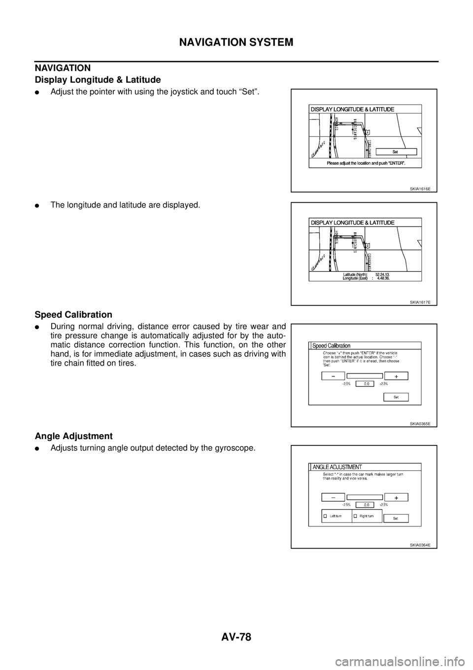
Display Longitude & Latitude
�Adjust the pointer with using the joystick and touch “Set”.
�The longitude and latitude are displayed.
Speed Calibration
�During normal driving, distance error caused by tire wear and
tire pressure change is automatically adjusted for by the auto-
matic distance correction function. This function, on the other
hand, is for immediate adjustment, in cases such as driving with
tire chain fitted on tires.
Angle Adjustment
�Adjusts turning angle output detected by the gyroscope.
SKIA1616E
SKIA1617E
SKIA0365E
SKIA0364E
Page 4092 of 4179
LT-14
HEADLAMP
Aiming Adjustment for HeadlampEKS003CG
When performing headlamp aiming adjustment, use an aiming machine, aiming wall screen or headlamp
tester. Aimers should be in good repair, calibrated and operated in accordance with respective operation man-
uals.
If any aimer is not available, aiming adjustment can be done as follows:
For details, refer to the regulations in your own country.
�Keep all tires inflated to correct pressures.
�Place vehicle and tester on one and same flat surface.
�See that there is no-load in vehicle (coolant, engine oil filled up to correct level and full fuel tank) other
than the driver (or equivalent weight placed in driver's position).
CAUTION:
Be sure aiming switch is set to “0” when performing aiming adjustment.
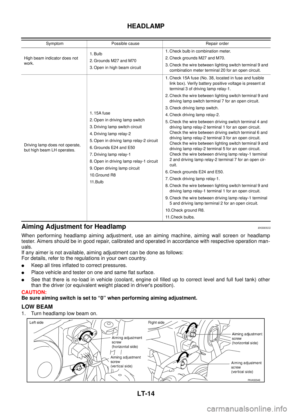
LOW BEAM
1. Turn headlamp low beam on.
High beam indicator does not
work.1. Bulb
2. Grounds M27 and M70
3. Open in high beam circuit1. Check bulb in combination meter.
2. Check grounds M27 and M70.
3. Check the wire between lighting switch terminal 9 and
combination meter terminal 20 for an open circuit.
Driving lamp does not operate,
but high beam LH operates.1. 15A fuse
2. Open in driving lamp switch
3. Driving lamp switch circuit
4. Driving lamp relay-2
5. Open in driving lamp relay-2 circuit
6. Grounds E24 and E50
7. Driving lamp relay-1
8. Open in driving lamp relay-1 circuit
9. Open driving lamp circuit
10.Ground R8
11 . B u l b1. Check 15A fuse (No. 38, located in fuse and fusible
link box). Verify battery positive voltage is present at
terminal 3 of driving lamp relay-1.
2. Check the wire between lighting switch terminal 9 and
driving lamp switch terminal 7 for an open circuit.
3. Check driving lamp switch.
4. Check driving lamp relay-2.
5. Check the wire between driving switch terminal 4 and
driving lamp relay-2 terminal 1 for an open circuit.
Check the wire between driving switch terminal 6 and
driving lamp relay-2 terminal 3 for an open circuit.
Check the wire between lighting switch terminal 9 and
driving lamp relay-2 terminal 5 for an open circuit.
Check the wire between driving lamp relay-1 terminal
2 and driving lamp relay-2 terminal 7 for an open cir-
cuit.
6. Check grounds E24 and E50.
7. Check driving lamp relay-1.
8. Check the wire between lighting switch terminal 9 and
driving lamp relay-1 terminal 1 for an open circuit.
9. Check the wire between driving lamp relay-1 terminal
5 and driving lamp terminal 2 for an open circuit.
10.Check ground R8.
11.Check bulbs. Symptom Possible cause Repair order
PKIA5554E
Page 4093 of 4179
HEADLAMP
LT-15
C
D
E
F
G
H
I
J
L
MA
B
LT
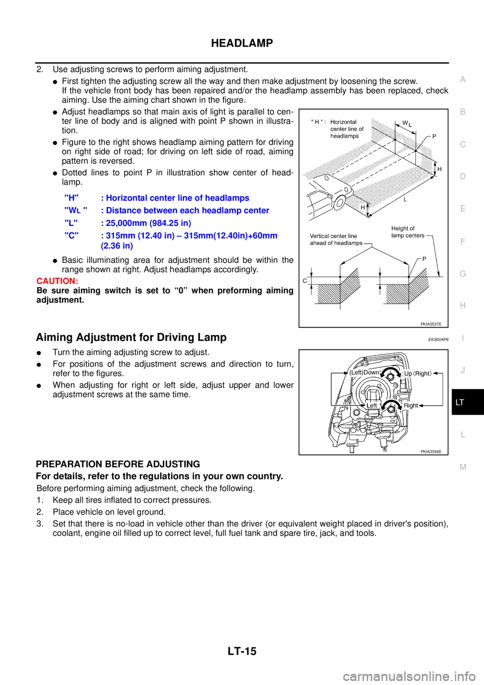
2. Use adjusting screws to perform aiming adjustment.
�First tighten the adjusting screw all the way and then make adjustment by loosening the screw.
If the vehicle front body has been repaired and/or the headlamp assembly has been replaced, check
aiming. Use the aiming chart shown in the figure.
�Adjust headlamps so that main axis of light is parallel to cen-
ter line of body and is aligned with point P shown in illustra-
tion.
�Figure to the right shows headlamp aiming pattern for driving
on right side of road; for driving on left side of road, aiming
pattern is reversed.
�Dotted lines to point P in illustration show center of head-
lamp.
�Basic illuminating area for adjustment should be within the
range shown at right. Adjust headlamps accordingly.
CAUTION:
Be sure aiming switch is set to “0” when preforming aiming
adjustment.
Aiming Adjustment for Driving LampEKS00AP6
�Turn the aiming adjusting screw to adjust.
�For positions of the adjustment screws and direction to turn,
refer to the figures.
�When adjusting for right or left side, adjust upper and lower
adjustment screws at the same time.
PREPARATION BEFORE ADJUSTING
For details, refer to the regulations in your own country.
Before performing aiming adjustment, check the following.
1. Keep all tires inflated to correct pressures.
2. Place vehicle on level ground.
3. Set that there is no-load in vehicle other than the driver (or equivalent weight placed in driver's position),
coolant, engine oil filled up to correct level, full fuel tank and spare tire, jack, and tools."H" : Horizontal center line of headlamps
"W
L " : Distance between each headlamp center
"L" : 25,000mm (984.25 in)
"C" : 315mm (12.40 in) – 315mm(12.40in)+60mm
(2.36 in)
PKIA3537E
PKIA3394E