Page 81 of 4179
IGNITION COIL
EM-29
[QR]
C
D
E
F
G
H
I
J
K
L
MA
EM
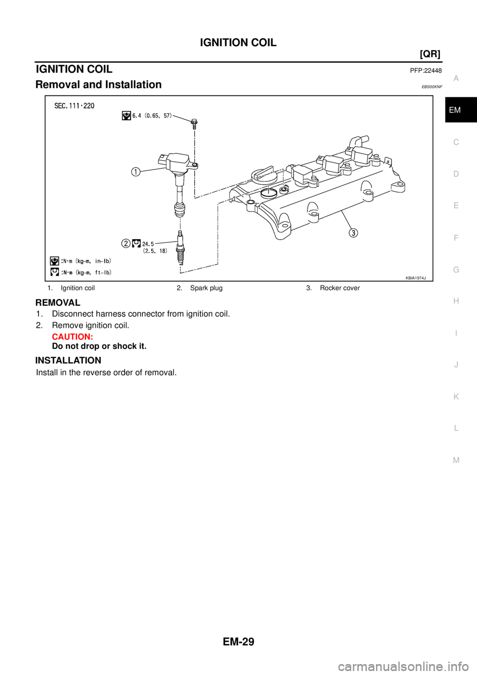
IGNITION COILPFP:22448
Removal and InstallationEBS00KNF
REMOVAL
1. Disconnect harness connector from ignition coil.
2. Remove ignition coil.
CAUTION:
Do not drop or shock it.
INSTALLATION
Install in the reverse order of removal.
1. Ignition coil 2. Spark plug 3. Rocker cover
KBIA1974J
Page 82 of 4179
EM-30
[QR]
SPARK PLUG
SPARK PLUG PFP:22401
Removal and InstallationEBS00KNG
REMOVAL
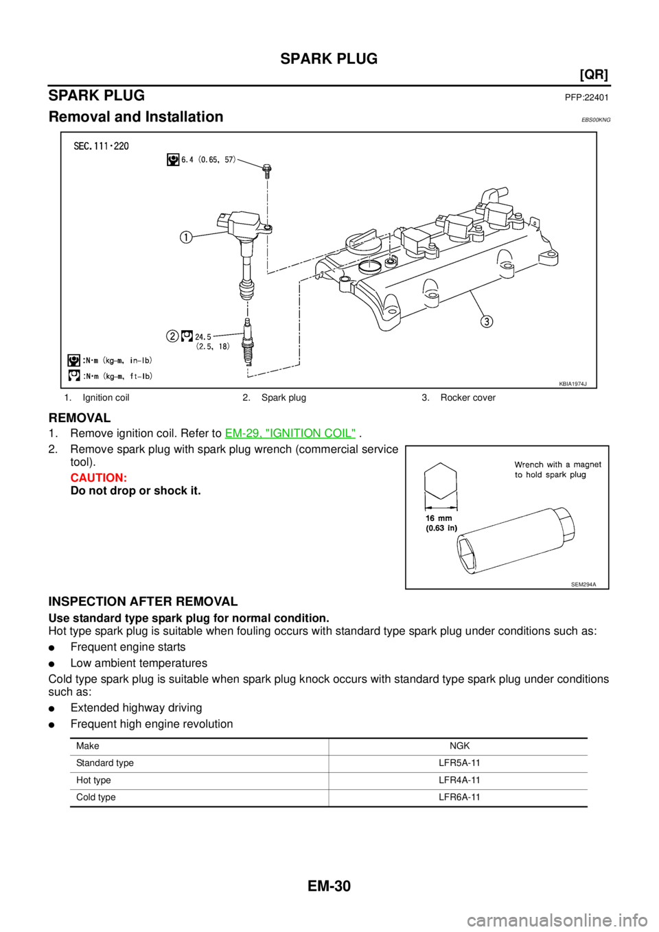
1. Remove ignition coil. Refer to EM-29, "IGNITION COIL" .
2. Remove spark plug with spark plug wrench (commercial service
tool).
CAUTION:
Do not drop or shock it.
INSPECTION AFTER REMOVAL
Use standard type spark plug for normal condition.
Hot type spark plug is suitable when fouling occurs with standard type spark plug under conditions such as:
�Frequent engine starts
�Low ambient temperatures
Cold type spark plug is suitable when spark plug knock occurs with standard type spark plug under conditions
such as:
�Extended highway driving
�Frequent high engine revolution
1. Ignition coil 2. Spark plug 3. Rocker cover
KBIA1974J
SEM294A
MakeNGK
Standard typeLFR5A-11
Hot typeLFR4A-11
Cold typeLFR6A-11
Page 94 of 4179
EM-42
[QR]
ROCKER COVER
ROCKER COVERPFP:13264
Removal and InstallationEBS00KNI
REMOVAL
1. Disconnect PCV hose from rocker cover.
2. Remove ignition coil. Refer to EM-29, "
IGNITION COIL" .
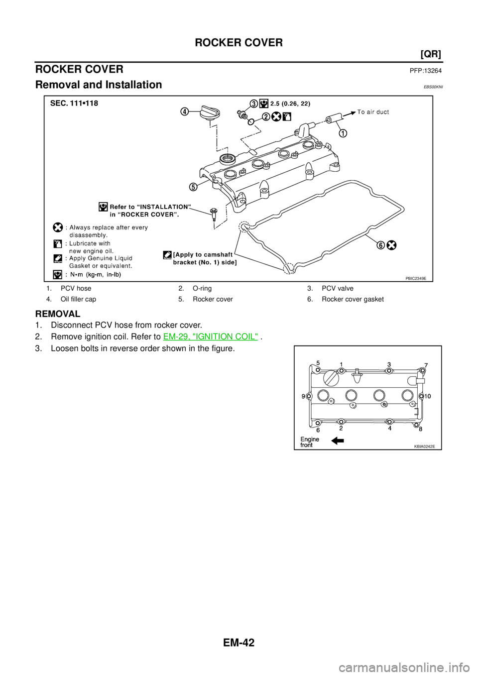
3. Loosen bolts in reverse order shown in the figure.
1. PCV hose 2. O-ring 3. PCV valve
4. Oil filler cap 5. Rocker cover 6. Rocker cover gasket
PBIC2349E
KBIA0242E
Page 97 of 4179
TIMING CHAIN
EM-45
[QR]
C
D
E
F
G
H
I
J
K
L
MA
EM
�Hood assembly; Refer to BL-12, "HOOD" .
�RH and LH undercovers
�PCV hose; Refer to EM-17, "INTAKE MANIFOLD" .
�Ignition coil; Refer to EM-29, "IGNITION COIL" .
�Rocker cover; Refer to EM-42, "ROCKER COVER" .
�Engine coolant reservoir tank; Refer to CO-12, "RADIATOR" .
�Drive belt; Refer to EM-13, "REMOVAL" .
�Alternator; Refer to SC-12, "CHARGING SYSTEM" .
�Drive belt auto-tensioner; Refer to EM-14, "REMOVAL" .
�Exhaust front tube; Refer to EX-2, "EXHAUST SYSTEM" .
2. Remove A/C compressor from engine. Temporarily secure A/C compressor to vehicle side with a rope to
avoid putting a load on them.
3. Remove bracket mounting bolts for fixing A/C piping on right strut housing and exhaust manifold cover.
Doing so simplifies moving.
4. Remove power steering oil pump with piping connected, and secure it to vehicle side temporarily. Refer to
PS-34, "
HYDRAULIC LINE" .
5. Remove power steering reservoir tank from bracket to move power steering piping. Refer to PS-34,
"HYDRAULIC LINE" .
CAUTION:
To avoid power steering fluid leakage, temporarily fix power steering reservoir tank vertically.
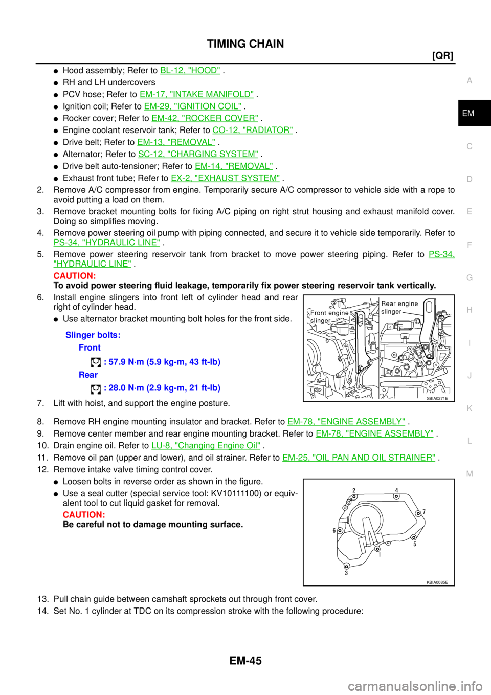
6. Install engine slingers into front left of cylinder head and rear
right of cylinder head.
�Use alternator bracket mounting bolt holes for the front side.
7. Lift with hoist, and support the engine posture.
8. Remove RH engine mounting insulator and bracket. Refer to EM-78, "
ENGINE ASSEMBLY" .
9. Remove center member and rear engine mounting bracket. Refer to EM-78, "
ENGINE ASSEMBLY" .
10. Drain engine oil. Refer to LU-8, "
Changing Engine Oil" .
11. Remove oil pan (upper and lower), and oil strainer. Refer to EM-25, "
OIL PAN AND OIL STRAINER" .
12. Remove intake valve timing control cover.
�Loosen bolts in reverse order as shown in the figure.
�U s e a s e a l c u t t e r ( s p e c i a l s e r v i c e t o o l : K V 1 0 1111 0 0 ) o r e q u i v -
alent tool to cut liquid gasket for removal.
CAUTION:
Be careful not to damage mounting surface.
13. Pull chain guide between camshaft sprockets out through front cover.
14. Set No. 1 cylinder at TDC on its compression stroke with the following procedure:Slinger bolts:
Front
: 57.9 N·m (5.9 kg-m, 43 ft-lb)
Rear
: 28.0 N·m (2.9 kg-m, 21 ft-lb)
SBIA0271E
KBIA0085E
Page 105 of 4179
CAMSHAFT
EM-53
[QR]
C
D
E
F
G
H
I
J
K
L
MA
EM
CAMSHAFTPFP:13001
Removal and InstallationEBS00LS2
NOTE:
This section describes removal/installation procedure of camshaft without removing front cover. If front cover
is removed or installed, removal of camshaft bracket (No. 1) is easier before step 8 and installation is easier
after step 3. Regarding removal and installation of front cover, refer to EM-44, "
TIMING CHAIN" .
REMOVAL
1. Release fuel pressure. Refer to EC-48, "FUEL PRESSURE RELEASE" (WITH EURO-OBD) or EC-510,
"FUEL PRESSURE RELEASE" (WITHOUT EURO-OBD).
2. Remove the following parts.
�Ignition coil; Refer to EM-29, "IGNITION COIL" .
�Rocker cover; Refer to EM-42, "ROCKER COVER" .
3. Remove power steering reservoir tank from bracket to move power steering piping. Refer to PS-34,
"HYDRAULIC LINE" .
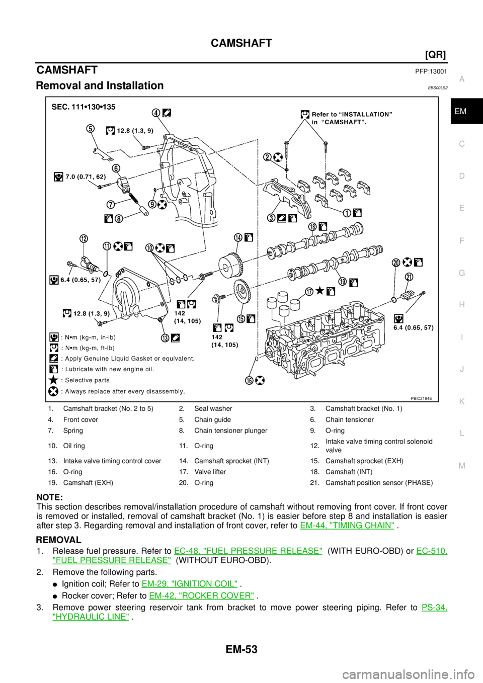
1. Camshaft bracket (No. 2 to 5) 2. Seal washer 3. Camshaft bracket (No. 1)
4. Front cover 5. Chain guide 6. Chain tensioner
7. Spring 8. Chain tensioner plunger 9. O-ring
10. Oil ring 11. O-ring 12.Intake valve timing control solenoid
valve
13. Intake valve timing control cover 14. Camshaft sprocket (INT) 15. Camshaft sprocket (EXH)
16. O-ring 17. Valve lifter 18. Camshaft (INT)
19. Camshaft (EXH) 20. O-ring 21. Camshaft position sensor (PHASE)
PBIC2184E
Page 119 of 4179
CYLINDER HEAD
EM-67
[QR]
C
D
E
F
G
H
I
J
K
L
MA
EM
CYLINDER HEADPFP:11041
On-Vehicle ServiceEBS00KNP
CHECKING COMPRESSION PRESSURE
1. Warm up engine thoroughly. Then, stop it.
2. Release fuel pressure by “Without CONSULT-II”. Refer to EC-48, "
FUEL PRESSURE RELEASE" (WITH
EURO-OBD) or EC-510, "
FUEL PRESSURE RELEASE" (WITHOUT EURO-OBD).
�Leave fuel pump fuse disconnecting to avoid fuel injection during measurement.
3. Remove ignition coil and spark plug from each cylinder. Refer to EM-29, "
IGNITION COIL" and EM-30,
"SPARK PLUG" .
4. Connect engine tachometer (not required in use of CONSULT-II).
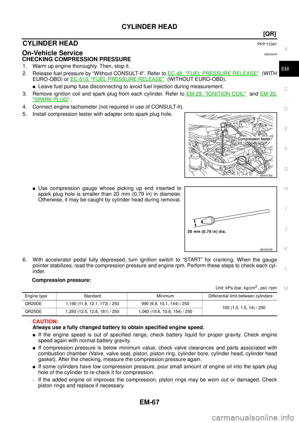
5. Install compression tester with adapter onto spark plug hole.
�Use compression gauge whose picking up end inserted to
spark plug hole is smaller than 20 mm (0.79 in) in diameter.
Otherwise, it may be caught by cylinder head during removal.
6. With accelerator pedal fully depressed, turn ignition switch to “START” for cranking. When the gauge
pointer stabilizes, read the compression pressure and engine rpm. Perform these steps to check each cyl-
inder.
Compression pressure:
Unit: kPa (bar, kg/cm2 , psi) /rpm
CAUTION:
Always use a fully changed battery to obtain specified engine speed.
�If the engine speed is out of specified range, check battery liquid for proper gravity. Check engine
speed again with normal battery gravity.
�If compression pressure is below minimum value, check valve clearances and parts associated with
combustion chamber (Valve, valve seat, piston, piston ring, cylinder bore, cylinder head, cylinder head
gasket). After the checking, measure the compression pressure again.
�If some cylinders have low compression pressure, pour small amount of engine oil into the spark plug
hole of the cylinder to re-check it for compression.
–If the added engine oil improves the compression, piston rings may be worn out or damaged. Check
piston rings and replace if necessary.
KBIA0130E
SBIA0533E
Engine type Standard Minimum Differential limit between cylinders
QR20DE 1,190 (11.9, 12.1, 173) / 250 990 (9.9, 10.1, 144) / 250
100 (1.0, 1.0, 14) / 250
QR25DE 1,250 (12.5, 12.8, 181) / 250 1,060 (10.6, 10.8, 154) / 250
Page 805 of 4179
IGNITION SIGNAL
EC-427
[QR (WITH EURO-OBD)]
C
D
E
F
G
H
I
J
K
L
MA
EC
IGNITION COIL WITH POWER TRANSISTOR
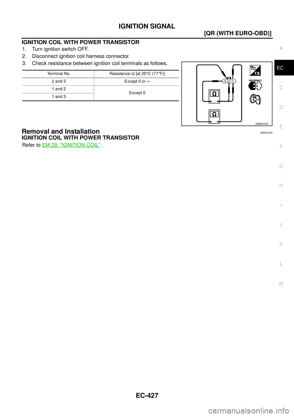
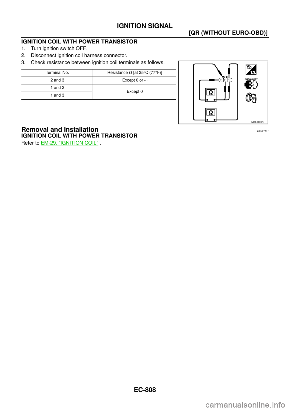
1. Turn ignition switch OFF.
2. Disconnect ignition coil harness connector.
3. Check resistance between ignition coil terminals as follows.
Removal and InstallationEBS010VA
IGNITION COIL WITH POWER TRANSISTOR
Refer to EM-29, "IGNITION COIL" .
Terminal No. Resistance Ω [at 25°C (77°F)]
2 and 3 Except 0 or ∞
1 and 2
Except 0
1 and 3
MBIB0032E
Page 1186 of 4179
EC-808
[QR (WITHOUT EURO-OBD)]
IGNITION SIGNAL
IGNITION COIL WITH POWER TRANSISTOR
1. Turn ignition switch OFF.
2. Disconnect ignition coil harness connector.
3. Check resistance between ignition coil terminals as follows.
Removal and InstallationEBS01141
IGNITION COIL WITH POWER TRANSISTOR
Refer to EM-29, "IGNITION COIL" .
Terminal No. Resistance Ω [at 25°C (77°F)]
2 and 3 Except 0 or ∞
1 and 2
Except 0
1 and 3
MBIB0032E