Page 3072 of 4179
BL-18
DOOR
DOORPFP:80100
Fitting AdjustmentEIS00A67
FRONT DOOR
Longitudinal clearance and surface height adjustment at front end
1. Remove fender protector. Refer to EI-21, "FENDER PROTECTOR" .
2. Working from the inside the fender, loosen hinge mount bolts on the body. Lift rear end of the front door to
adjust clearance and surface difference properly.
REAR DOOR
Longitudinal clearance and surface height adjustment at front end
1. Remove upper and lower garnishes on the center pillar. Refer to EI-35, "BODY SIDE TRIM" .
2. Loosen mounting bolts from outside of vehicle, mounting nuts from inside of vehicle. Open rear door.
Raise rear end of it to adjust.
STRIKER ADJUSTMENT
Adjust striker until it is parallel to the lock engagement direction.
PIIA3652E
PIIA0555E
Page 3294 of 4179
RF-14
SUNROOF
Fitting AdjustmentEIS000MR
LONGITUDINAL/LATERAL CLEARANCE ADJUSTMENT
1. Tilt up glass lid and then remove side trim.
2. After loosening glass lid mounting nuts, tilt down glass lid.
3. Adjust glass lid according to sections A–A, B–B, C–C as shown in the figure.
4. After adjusting glass lid, tighten nuts to the specified torque.
5. Tilt glass lid 4 to 5 times to check that it smoothly goes up and down.
SURFACE MISMATCH ADJUSTMENT
1. Adjust surface height of glass lid and roof panel to 0 ± 1.5 mm
(0±0.059 in) by altering the number of shims between glass lid
and link assembly. (Standard: 2, max: 4)
2. After fitting adjustment, use a hose to flush the entire surface of
the roof with water to check for leaks.
PIIA3748E
SIIA0119E
Page 4094 of 4179

LT-16
HEADLAMP
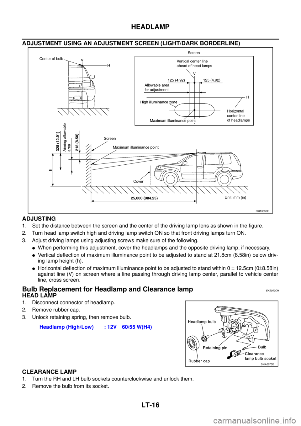
ADJUSTMENT USING AN ADJUSTMENT SCREEN (LIGHT/DARK BORDERLINE)
ADJUSTING
1. Set the distance between the screen and the center of the driving lamp lens as shown in the figure.
2. Turn head lamp switch high and driving lamp switch ON so that front driving lamps turn ON.
3. Adjust driving lamps using adjusting screws make sure of the following.
�When performing this adjustment, cover the headlamps and the opposite driving lamp, if necessary.
�Vertical deflection of maximum illuminance point to be adjusted to stand at 21.8cm (8.58in) below driv-
ing lamp height (h).
�Horizontal deflection of maximum illuminance point to be adjusted to stand within 0 ± 12.5cm (0±8.58in)
against line (V) on screen where a line passing through driving lamp center, parallel to vehicle center
line, cross screen.
Bulb Replacement for Headlamp and Clearance lampEKS003CH
HEAD LAMP
1. Disconnect connector of headlamp.
2. Remove rubber cap.
3. Unlock retaining spring, then remove bulb.
CLEARANCE LAMP
1. Turn the RH and LH bulb sockets counterclockwise and unlock them.
2. Remove the bulb from its socket.
PKIA3395E
Headlamp (High/Low) : 12V 60/55 W(H4)
SKIA0073E
Page 4132 of 4179
LT-54
FRONT FOG LAMP
Aiming Adjustment EKS003DH
1. Set the distance between the screen and the center of the fog
lamp lens as shown at left.
2. Turn front fog lamps ON.
3. Insert a phillips screwdriver into the access hole and enage the
tip of the screwdriver with the gear of the adjuster as shown at
left. The aiming adjuster can now be turned by turning the
screwdriver.
4. Adjust front fog lamps so that the top edge of the high intensity
zone is 100 mm (4 in) below the height of the fog lamp centers
as shown at left.
�When performing adjustment, if necessary, cover the head-
lamps and opposite fog lamp.
PKIA8619E
PKIA5558E
MEL328G