Page 2795 of 4179

FRONT DISC BRAKE
BR-31
C
D
E
G
H
I
J
K
L
MA
B
BR
2. Apply brake fluid or rubber lubricant to piston boots. Cover pis-
ton end with piston boot. Install cylinder side boot lip properly
into groove on cylinder body.
CAUTION:
Do not reuse piston boot.
3. Apply brake fluid to piston. Press piston into cylinder body by
hand. Assemble piston side boot lip properly into groove on pis-
ton.
CAUTION:
Press piston evenly and change pressing point to prevent
cylinder inner wall from being rubbed.
BRAKE BURNISHING PROCEDURE
Burnish the brake pad contact surfaces according to the following procedure after refinishing or replacing
drums or rotors, after replacing pads or linings, or if a soft pedal occurs at very low mileage.
CAUTION:
Only perform this procedure under safe road and traffic conditions. Use extreme caution.
1. Drive vehicle on a straight smooth road at 50 km/h (31 MPH).
2. Use medium brake pedal/foot effort to bring vehicle to a complete stop from 50 km/h (31 MPH).
Adjust brake pedal/foot pressure such that vehicle stopping time equals 3 to 5 seconds.
3. To cool the brake system, drive vehicle at 50 km/h (31 MPH) for 1 minute without stopping.
4. Repeat steps 1 to 3, 10 times or more to complete the burnishing procedure.
SFIA0155E
SBR574
Page 2796 of 4179

BR-32
REAR DISC BRAKE
REAR DISC BRAKEPFP:44000
ComponentEFS0017X
WARNING:
�Clean dust on brake caliper and pad with a vacuum dust collector. Do not blow with compressed
air.
CAUTION:
�Never depress brake pedal while removing cylinder body because piston will pop out.
�Do not remove brake hose and torque member mounting bolts unless disassembling or replacing
caliper assembly. Hang the cylinder body with a wire so that the brake hose is not under tension.
�Be careful not to damage piston boot. Do not allow brake fluid to get the rotor.
�When replacing brake pads, always replace inner shims, outer shims, and shim covers as a set.
InspectionEFS0017Y
PAD WEAR INSPECTION
Check pad thickness by lifting vehicle, removing tyre and wheel, and
looking through check hole on cylinder body. If necessary, use a
scale.
1. Pad retainer 2. Outer shim cover 3. Outer shim
4. Outer pad 5. Pad retainer 6. Inner pad
7. Inner shim 8. Inner shim cover 9. Sliding pin boot
10. Sliding pin 11. Sliding pin bolt 12. Cylinder body
13. Copper washer 14. Brake hose 15. Union bolt
16. Copper washer 17. Bleed valve 18. Piston seal
19. Piston 20. Piston boot 21. Retaining ring
22. Torque member
SFIA2143E
standard thickness : 8.5 mm (0.335 in)
pad wear limit : 2.0 mm (0.079 in)
BRA0010D
Page 2798 of 4179

BR-34
REAR DISC BRAKE
Caliper Removal and InstallationEFS00180
REMOVAL
1. Connect a vinyl tube to bleed valve.
2. Drain brake fluid gradually from bleed valve while depressing
brake pedal.
3. Remove union bolt and remove brake hose from caliper assem-
bly.
4. Remove union bolts and torque member mounting bolts, and
remove caliper assembly.
5. Remove disc rotor.
INSTALLATION
CAUTION:
�Refill with new brake fluid “DOT 3 or DOT 4”.
�Never reuse drained brake fluid.
1. Install disc rotor.
2. Install caliper assembly. Tighten mounting bolts to the specified torque.
CAUTION:
Wipe brake fluid and grease on axle assembly washer seats and caliper assembly mounting sur-
face. Install caliper assembly.
3. Connect brake hose to caliper assembly and tighten union bolts to the specified torque.
CAUTION:
�Do not reuse the copper washer for union bolts.
�Securely assemble brake hose to protrusions on cylinder body.
4. Bleed air. Refer to BR-9, "
Bleeding Brake System" .
Caliper Disassembly and AssemblyEFS00181
DISASSEMBLY
WARNING:
Be careful not to pinch your fingers in the piston.
CAUTION:
Be careful not to damage the cylinder inner wall.
1. Remove caliper assembly from vehicle.
2. Remove sliding pin from cylinder body. Then remove pads, shims, shim covers, and pad retainers from
caliper assembly.
3. Remove sliding pin boots from torque member.
4. Using flat-bladed screwdriver (as shown in the figure), remove
retaining ring.
SFIA0143E
SBR028A
Page 2799 of 4179

REAR DISC BRAKE
BR-35
C
D
E
G
H
I
J
K
L
MA
B
BR
5. Place a wooden block as shown in the figure. Blow air into union
bolt mounting hole to remove pistons and piston boots.
6. Using flat-bladed screwdriver, remove piston seals.
INSPECTION AFTER DISASSEMBLY
Cylinder Body
CAUTION:
Use new brake fluid to clean. Never use mineral oils such as gasoline or kerosene.
�Check cylinder inner wall for corrosion, wear and damage. If corrosion, wear or damage is detected,
replace the cylinder body.
�Minor flaws caused by corrosion or foreign material can be removed by polishing the surface with fine
sandpaper. Replace the cylinder body, if necessary.
To r q u e M e m b e r
Check for wear, cracks and damage. If wear, cracks or damage is detected, replace the applicable part.
Piston
CAUTION:
The piston sliding surface is plated. Do not polish with sandpaper.
Check piston surface for corrosion, wear and damage. If corrosion, wear or damage is detected, replace the
applicable part.
Sliding Pin, Pin Bolt and Pin Boot
Check sliding pin and sliding pin boot for wear, damage and cracks. If corrosion, wear or damage is detected,
replace the applicable part.
DISC ROTOR INSPECTION
Visual Inspection
Check surface of the disc rotor for uneven wear, cracks and serious damage. If uneven wear, cracks or seri-
ous damage is detected, replace it.
Run Out Inspection
1. Using wheel nuts, fix the disc rotor to wheels hub. (2 or more positions)
BRD0041D
SFIA0340E
Page 2800 of 4179

BR-36
REAR DISC BRAKE
2. Using a dial indicator, check run out.
NOTE:
Make sure that wheel bearing axial endplay is with in the specifi-
cation before measuring runout. Refer to FA X - 7 , "
On-Vehicle
Inspection" .
3. If the run out is outside the limit, find the minimum run out point by shifting the mounting positions of disc
rotor and wheel hub by one hole.
Thickness Inspection
Using a micrometer, check thickness of disc rotor. If the thickness is
outside the standard, replace disc rotor.
ASSEMBLY
CAUTION:
When assembling, do not use rubber grease.
1. Apply rubber lubricant to piston seals, and install them to the cyl-
inder body.
CAUTION:
Do not reuse piston seals.
2. Apply brake fluid to piston boots. Cover piston end with piston
boot. Install cylinder side boot lip properly into groove on cylin-
der body.
CAUTION:
Do not reuse piston boot.
3. Press piston into cylinder body by hand. Assemble piston side
boot lip properly into groove on the piston.
CAUTION:
Press piston evenly and change pressing point to prevent
the cylinder inner wall from being rubbed.Measurement point:
At a point of 10 mm (0.39 in) from the outer
edge of the disc.
Run out limit:
0.07 mm (0.0028 in) or less
BRA0013D
Standard thickness : 16.0 mm (0.630 in)
Wear limit : 14.0 mm (0.551 in)
Maximum uneven wear (measured at 8 positions):
0.02 mm (0.0008 in) or less
SBR020B
SFIA0156E
SFIA0157E
Page 2802 of 4179

SERVICE DATA AND SPECIFICATIONS (SDS)PFP:00030
General SpecificationsEFS000CQ
Unit: mm (in)
Brake PedalEFS000CR
Check ValveEFS000CS
Brake BoosterEFS000CT")
BR-38
SERVICE DATA AND SPECIFICATIONS (SDS)
SERVICE DATA AND SPECIFICATIONS (SDS)PFP:00030
General SpecificationsEFS000CQ
Unit: mm (in)
Brake PedalEFS000CR
Check ValveEFS000CS
Brake BoosterEFS000CT
Vacuum type
Front Disc BrakeEFS000CU
Front brakeBrake model AD31VD
Cylinder bore diameter 44.4 × 2 (1.748 × 0.08)
Pad
Length x width x thickness132.0 × 52.5 × 11.0
(5.20 × 2.067 × 0.433)
Rotor outer diameter x thickness 280 × 28 (11.02 × 1.10)
Rear brakeBrake model AD9VA
Cylinder bore diameter 34.9 (1.374)
Pad
Length x width x thickness83.0 × 33.0 × 8.5
(3.268 × 1.299 × 0.335)
Rotor outer diameter x thickness 292 × 16 (11.50 × 0.63)
Master cylinder Cylinder bore diameter 25.4 (1)
Control valve Valve model Electronic control type
Brake boosterBooster model C215T
Diaphragm diameterPrimary 230 (9.06)
Secondary 205 (8.07)
Recommended brake fluid DOT 3 or DOT 4
Pedal play3 - 11 mm (0.12 - 0.43 in)
Looseness at clevis pin 1 - 3 mm (0.04 - 0.12 in)
Brake pedal height (from dash panel top surface)M/T model 156 - 166 mm (6.14 - 6.54 in)
A/T model 164 - 174 mm (6.46 - 6.85 in)
Depressed pedal height under a force of 490 N (50 kg,110.6 lb)
(from dash panel top surface)M/T model 80 mm (3.15 in) or more
A/T model 85 mm (3.35 in) or more
Clearance between threaded end of stop lamp switch and pedal stopper 0.74 - 1.96 mm (0.0291 - 0.0772 in)
Vacuum leakage [at vacuum of 66.7 kPa (-500 mmHg, -19.69
inHg)]Within 1.3 kPa (10 mmHg, 0.39 inHg) of vacuum for 15 seconds
Vacuum leakage [at vacuum of -66.7 kPa (-500 mmHg, -19.69
inHg)]Within 3.3 kPa (25 mmHg, 0.98 inHg) of vacuum for 15 seconds
Input rod installation standard dimension 125 mm (4.92 in)
Brake typeAD31VD
Brake padStandard thickness (new) 11 mm (0.43 in)
Repair limit thickness 2.0 mm (0.079 in)
Disc rotorStandard thickness (new) 28.0 mm (1.102 in)
Repair limit thickness 26.0 mm (1.024 in)
Runout limit 0.04 mm (0.0016 in)
Page 2803 of 4179
SERVICE DATA AND SPECIFICATIONS (SDS)
BR-39
C
D
E
G
H
I
J
K
L
MA
B
BR
Rear Disc BrakeEFS000CV
Brake typeAD9VA
Brake padStandard thickness (new) 8.5 mm (0.335 in)
Repair limit thickness 2.0 mm (0.079 in)
Disc rotorStandard thickness (new) 16.0 mm (0.63 in)
Repair limit thickness 14.0 mm (0.55 in)
Runout limit 0.07 mm (0.0028 in)
Page 2809 of 4179
PARKING BRAKE SHOE
PB-5
C
D
E
G
H
I
J
K
L
MA
B
PB
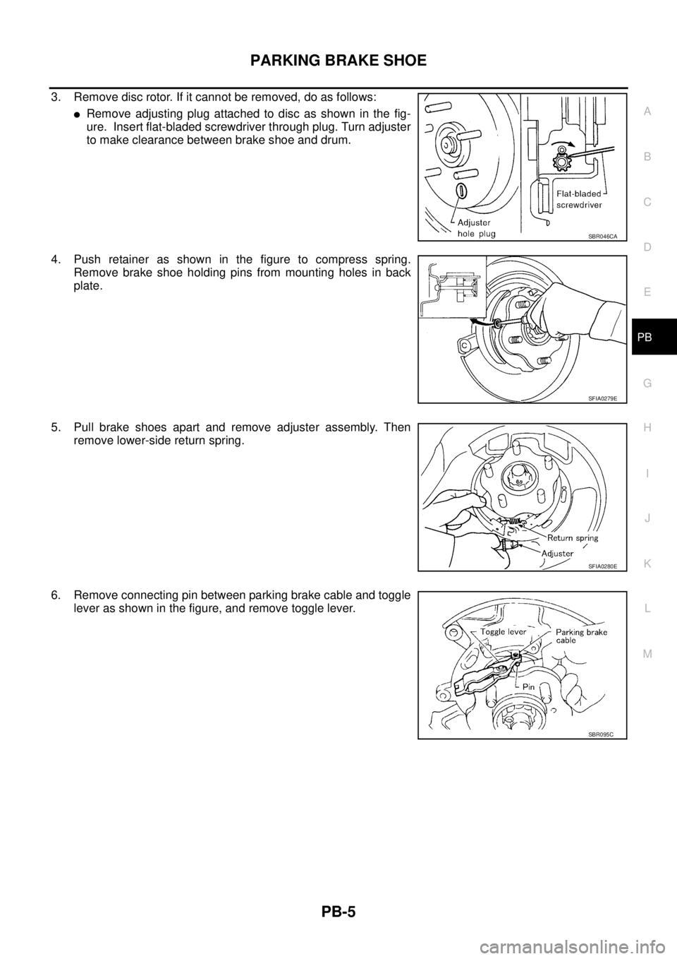
3. Remove disc rotor. If it cannot be removed, do as follows:
�Remove adjusting plug attached to disc as shown in the fig-
ure. Insert flat-bladed screwdriver through plug. Turn adjuster
to make clearance between brake shoe and drum.
4. Push retainer as shown in the figure to compress spring.
Remove brake shoe holding pins from mounting holes in back
plate.
5. Pull brake shoes apart and remove adjuster assembly. Then
remove lower-side return spring.
6. Remove connecting pin between parking brake cable and toggle
lever as shown in the figure, and remove toggle lever.
SBR046CA
SFIA0279E
SFIA0280E
SBR095C

BR-39
C
D
E
G
H
I
J
K
L
MA
B
BR
Rear Disc BrakeEFS000CV
Brake typeAD9VA
Brake padStandard thickness (new) 8.5 mm (0.335 in)
Repair limit thickness 2.0 mm (0.079")