Page 2047 of 4179
PRECAUTIONS
AT-11
D
E
F
G
H
I
J
K
L
MA
B
AT
�Converter is contaminated with engine coolant containing antifreeze.
�Internal failure of stator roller clutch.
�Heavy clutch debris due to overheating (blue converter).
�Steel particles or clutch lining material found in fluid filter or on magnet when no internal parts in unit are
worn or damaged — indicates that lining material came from converter.
The torque converter should not be replaced if:
�The fluid has an odor, is discolored, and there is no evidence of metal or clutch facing particles.
�The threads in one or more of the converter bolt holes are damaged.
�Transaxle failure did not display evidence of damaged or worn internal parts, steel particles or clutch plate
lining material in unit and inside the fluid filter.
�Vehicle has been exposed to high mileage (only). The exception may be where the torque converter
clutch dampener plate lining has seen excess wear by vehicles operated in heavy and/or constant traffic,
such as taxi, delivery or police use.
EURO-OBD SELF-DIAGNOSIS — EURO-OBD —
�A/T self-diagnosis is performed by the TCM in combination with the ECM. The results can be read through
the blinking pattern of the O/D OFF indicator lamp or the malfunction indicator lamp (MIL). Refer to the
table on AT- 4 5 , "
SELF-DIAGNOSTIC RESULT TEST MODE" for the indicator used to display each self-
diagnostic result.
�The self-diagnostic results indicated by the MIL are automatically stored in both the ECM and TCM mem-
ories.
Always perform the procedure “HOW TO ERASE DTC” on AT- 4 2 , "
HOW TO ERASE DTC" to com-
plete the repair and avoid unnecessary blinking of the MIL.
�The following self-diagnostic items can be detected using ECM self-diagnostic results mode* only when
the O/D OFF indicator lamp does not indicate any malfunctions.
–PNP switch
–A/T 1st, 2nd, 3rd, or 4th gear function
*: For details of EURO-OBD, refer to EC-51, "
ON BOARD DIAGNOSTIC (OBD) SYSTEM" .
�Certain systems and components, especially those related to EURO-OBD, may use a new style
slide-locking type harness connector.
For description and how to disconnect, refer to PG-70, "
HARNESS CONNECTOR" .
Wiring Diagrams and Trouble DiagnosisECS004Q4
When you read wiring diagrams, refer to the following:
�GI-14, "How to Read Wiring Diagrams"
�PG-2, "POWER SUPPLY ROUTING"
When you perform trouble diagnosis, refer to the following:
�GI-10, "HOW TO FOLLOW TEST GROUPS IN TROUBLE DIAGNOSES"
�GI-23, "How to Perform Efficient Diagnosis for an Electrical Incident"
Page 3409 of 4179
PRECAUTIONS
ATC-13
C
D
E
F
G
H
I
K
L
MA
B
AT C
IDENTIFICATION
NOTE:
Vehicles with factory installed fluorescent dye have a green label.
Vehicles without factory installed fluorescent dye have a blue label.
IDENTIFICATION LABEL FOR VEHICLE
Vehicles with factory installed fluorescent dye have this identification
label on the front side of hood.
Wiring Diagrams and Trouble DiagnosisEJS000T9
When you read wiring diagrams, refer to the following:
�GI-14, "How to Read Wiring Diagrams" in GI section.
�PG-3, "Wiring Diagram - POWER -" in PG section.
When you perform trouble diagnosis, refer to the following:
�GI-10, "How to Follow Trouble Diagnoses" in GI section.
�GI-23, "How to Perform Efficient Diagnosis for an Electrical Incident" in GI section.
RJIA2721E
SHA867F
Page 3411 of 4179
PREPARATION
ATC-15
C
D
E
F
G
H
I
K
L
MA
B
AT C
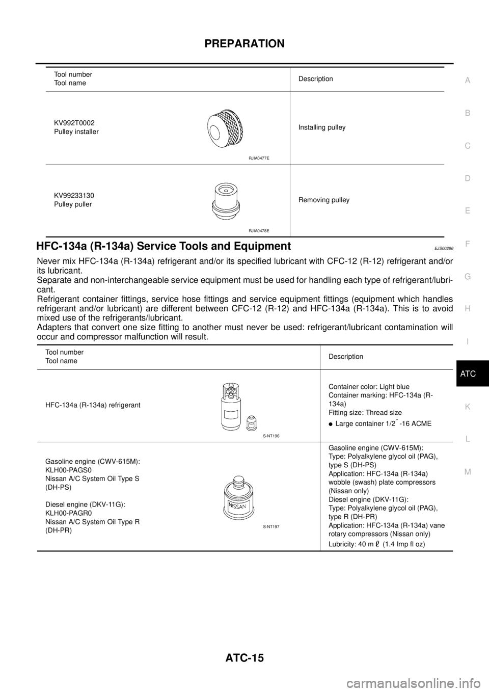
HFC-134a (R-134a) Service Tools and EquipmentEJS00286
Never mix HFC-134a (R-134a) refrigerant and/or its specified lubricant with CFC-12 (R-12) refrigerant and/or
its lubricant.
Separate and non-interchangeable service equipment must be used for handling each type of refrigerant/lubri-
cant.
Refrigerant container fittings, service hose fittings and service equipment fittings (equipment which handles
refrigerant and/or lubricant) are different between CFC-12 (R-12) and HFC-134a (R-134a). This is to avoid
mixed use of the refrigerants/lubricant.
Adapters that convert one size fitting to another must never be used: refrigerant/lubricant contamination will
occur and compressor malfunction will result.
KV992T0002
Pulley installerInstalling pulley
KV99233130
Pulley pullerRemoving pulley Tool number
Tool nameDescription
RJIA0477E
RJIA0478E
Tool number
Tool nameDescription
HFC-134a (R-134a) refrigerantContainer color: Light blue
Container marking: HFC-134a (R-
134a)
Fitting size: Thread size
�Large container 1/2″ -16 ACME
Gasoline engine (CWV-615M):
KLH00-PAGS0
Nissan A/C System Oil Type S
(DH-PS)
Diesel engine (DKV-11G):
KLH00-PAGR0
Nissan A/C System Oil Type R
(DH-PR)Gasoline engine (CWV-615M):
Type: Polyalkylene glycol oil (PAG),
type S (DH-PS)
Application: HFC-134a (R-134a)
wobble (swash) plate compressors
(Nissan only)
Diesel engine (DKV-11G):
Type: Polyalkylene glycol oil (PAG),
type R (DH-PR)
Application: HFC-134a (R-134a) vane
rotary compressors (Nissan only)
Lubricity: 40 m (1.4 Imp fl oz)
S-NT196
S-NT197
Page 3413 of 4179
PREPARATION
ATC-17
C
D
E
F
G
H
I
K
L
MA
B
AT C
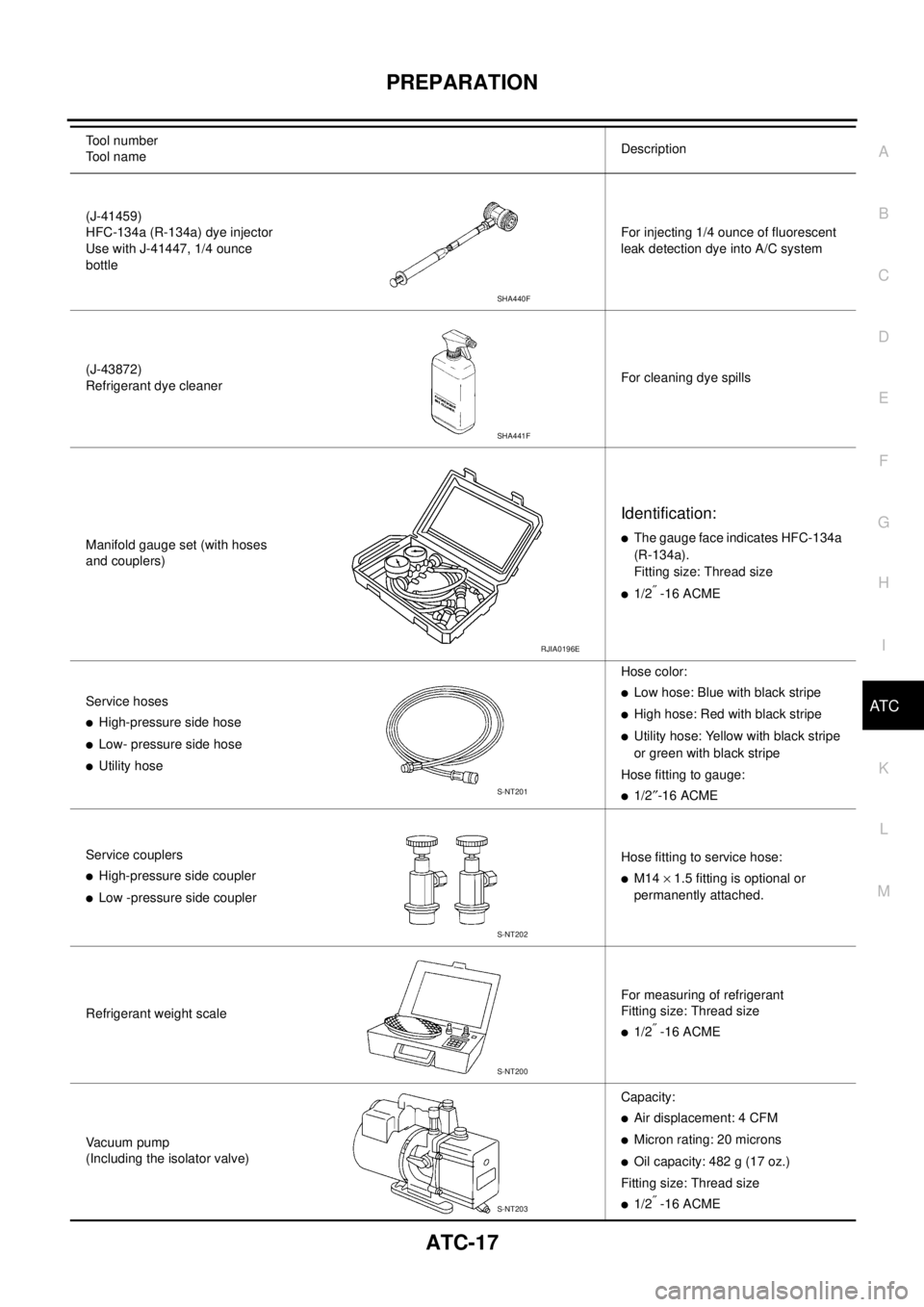
(J-41459)
HFC-134a (R-134a) dye injector
Use with J-41447, 1/4 ounce
bottleFor injecting 1/4 ounce of fluorescent
leak detection dye into A/C system
(J-43872)
Refrigerant dye cleanerFor cleaning dye spills
Manifold gauge set (with hoses
and couplers)
Identification:
�The gauge face indicates HFC-134a
(R-134a).
Fitting size: Thread size
�1/2″ -16 ACME
Service hoses
�High-pressure side hose
�Low- pressure side hose
�Utility hoseHose color:
�Low hose: Blue with black stripe
�High hose: Red with black stripe
�Utility hose: Yellow with black stripe
or green with black stripe
Hose fitting to gauge:
�1/2″-16 ACME
Service couplers
�High-pressure side coupler
�Low -pressure side couplerHose fitting to service hose:
�M14 × 1.5 fitting is optional or
permanently attached.
Refrigerant weight scaleFor measuring of refrigerant
Fitting size: Thread size
�1/2″ -16 ACME
Vacuum pump
(Including the isolator valve)Capacity:
�Air displacement: 4 CFM
�Micron rating: 20 microns
�Oil capacity: 482 g (17 oz.)
Fitting size: Thread size
�1/2″ -16 ACME Tool number
Tool nameDescription
SHA440F
SHA441F
RJIA0196E
S-NT201
S-NT202
S-NT200
S-NT203
Page 3955 of 4179
NAVIGATION SYSTEM
AV-65
C
D
E
F
G
H
I
J
L
MA
B
AV
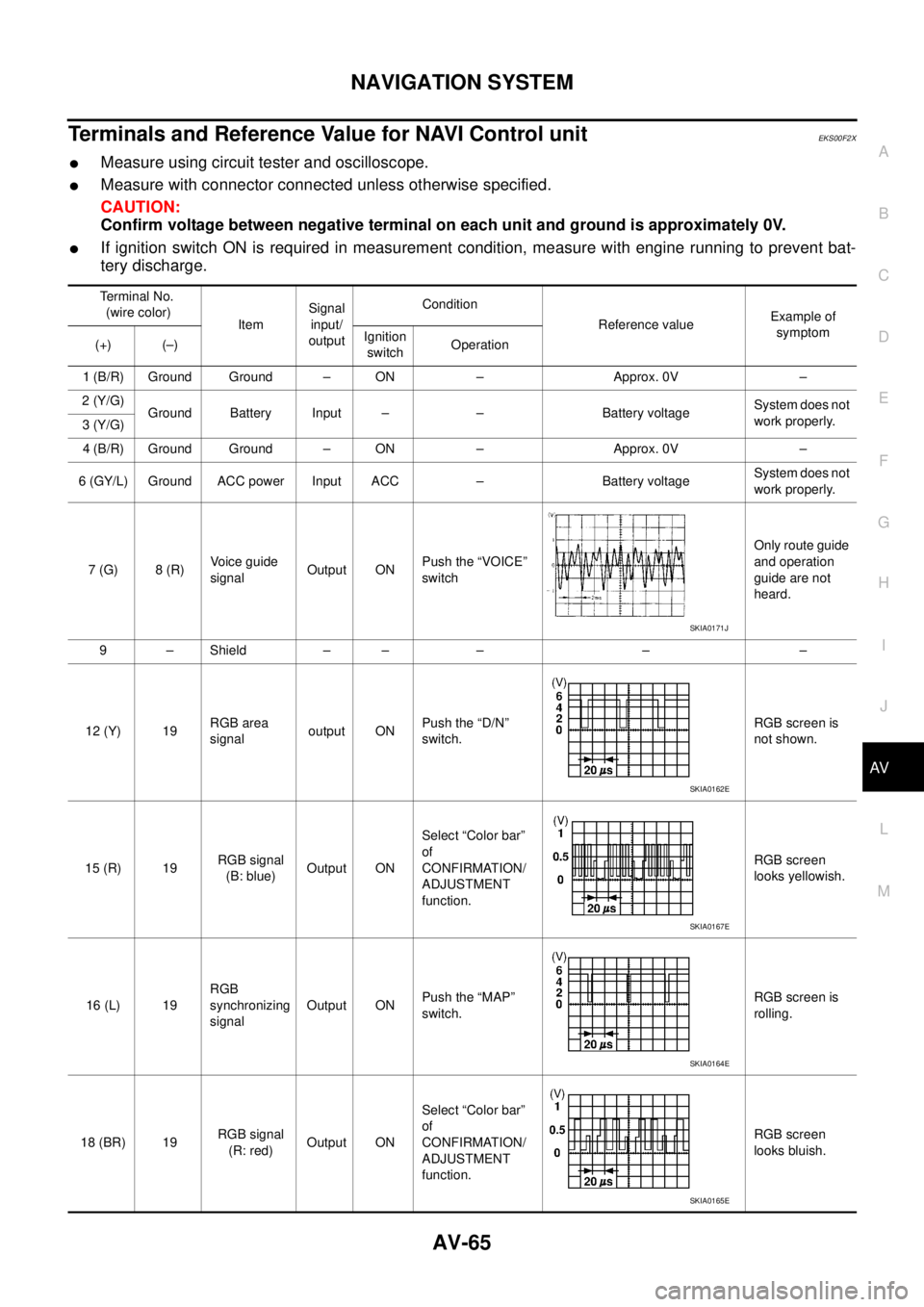
Terminals and Reference Value for NAVI Control unitEKS00F2X
�Measure using circuit tester and oscilloscope.
�Measure with connector connected unless otherwise specified.
CAUTION:
Confirm voltage between negative terminal on each unit and ground is approximately 0V.
�If ignition switch ON is required in measurement condition, measure with engine running to prevent bat-
tery discharge.
Terminal No.
(wire color)
ItemSignal
input/
outputCondition
Reference valueExample of
symptom
(+) (–)Ignition
switchOperation
1 (B/R) Ground Ground – ON – Approx. 0V –
2 (Y/G)
Ground Battery Input – – Battery voltageSystem does not
work properly.
3 (Y/G)
4 (B/R) Ground Ground – ON – Approx. 0V –
6 (GY/L) Ground ACC power Input ACC – Battery voltageSystem does not
work properly.
7 (G) 8 (R)Voice guide
signalOutput ONPush the “VOICE”
switchOnly route guide
and operation
guide are not
heard.
9 – Shield – – – – –
12 (Y) 19RGB area
signaloutput ONPush the “D/N”
switch.RGB screen is
not shown.
15 (R) 19RGB signal
(B: blue)Output ONSelect “Color bar”
of
CONFIRMATION/
ADJUSTMENT
function.RGB screen
looks yellowish.
16 (L) 19RGB
synchronizing
signalOutput ONPush the “MAP”
switch.RGB screen is
rolling.
18 (BR) 19RGB signal
(R: red)Output ONSelect “Color bar”
of
CONFIRMATION/
ADJUSTMENT
function.RGB screen
looks bluish.
SKIA0171J
SKIA0162E
SKIA0167E
SKIA0164E
SKIA0165E
Page 3957 of 4179
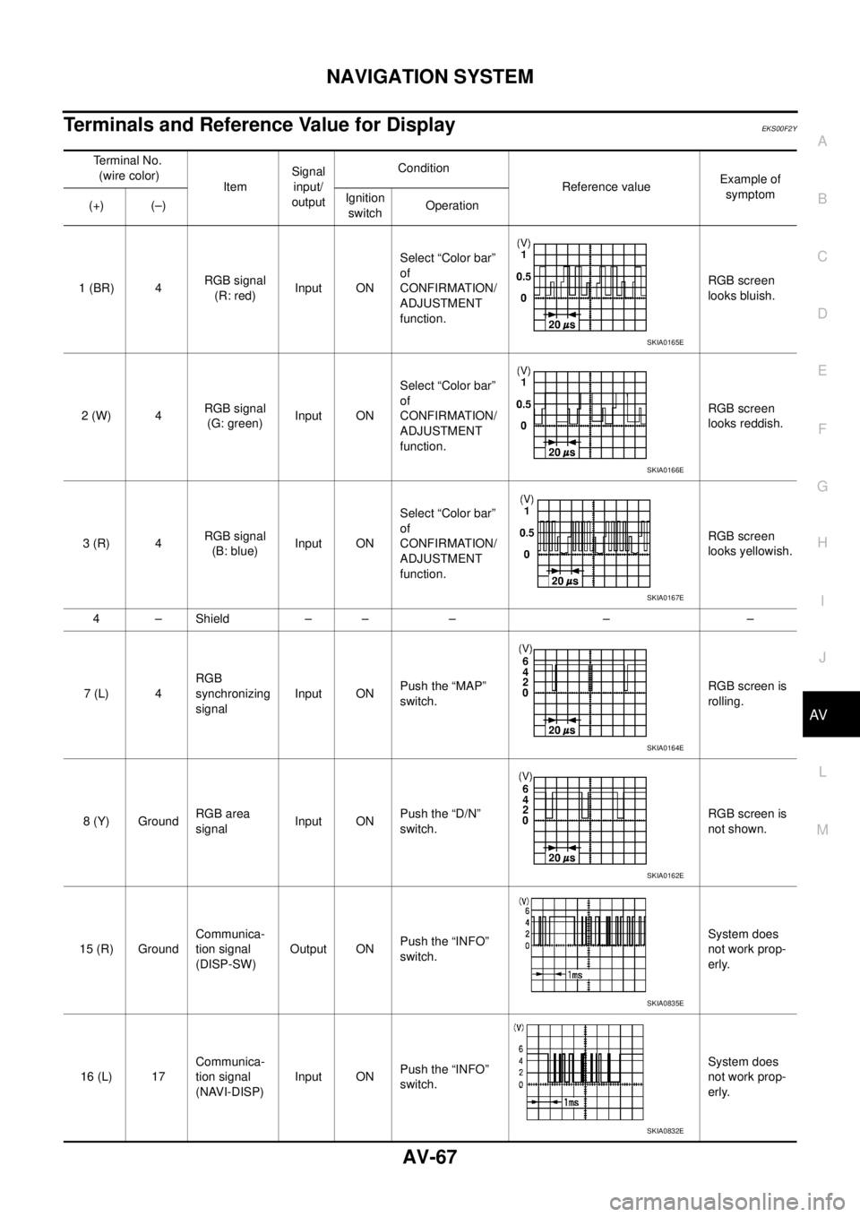
NAVIGATION SYSTEM
AV-67
C
D
E
F
G
H
I
J
L
MA
B
AV
Terminals and Reference Value for DisplayEKS00F2Y
Terminal No.
(wire color)
ItemSignal
input/
outputCondition
Reference valueExample of
symptom
(+) (–)Ignition
switchOperation
1 (BR) 4RGB signal
(R: red)Input ONSelect “Color bar”
of
CONFIRMATION/
ADJUSTMENT
function.RGB screen
looks bluish.
2 (W) 4RGB signal
(G: green)Input ONSelect “Color bar”
of
CONFIRMATION/
ADJUSTMENT
function.RGB screen
looks reddish.
3 (R) 4RGB signal
(B: blue)Input ONSelect “Color bar”
of
CONFIRMATION/
ADJUSTMENT
function.RGB screen
looks yellowish.
4–Shield –– – – –
7 (L) 4RGB
synchronizing
signalInput ONPush the “MAP”
switch.RGB screen is
rolling.
8 (Y) GroundRGB area
signalInput ONPush the “D/N”
switch.RGB screen is
not shown.
15 (R) GroundCommunica-
tion signal
(DISP-SW)Output ONPush the “INFO”
switch.System does
not work prop-
erly.
16 (L) 17Communica-
tion signal
(NAVI-DISP)Input ONPush the “INFO”
switch.System does
not work prop-
erly.
SKIA0165E
SKIA0166E
SKIA0167E
SKIA0164E
SKIA0162E
SKIA0835E
SKIA0832E
Page 3966 of 4179
AV-76
NAVIGATION SYSTEM
4. When “Confirmation / Adjustment” is selected on the initial trou-
ble diagnosis screen, the operation will enter the CONFIRMA-
TION/ADJUSTMENT mode. In this mode, check and adjustment
of each item will become possible.
5. Select each switch on “Confirmation / Adjustment” screen to dis-
play the relevant diagnosis screen.
DISPLAY
CAUTION:
When Display Color Spectrum Bar screen is completed after “BACK” switch is Pushed, the screen
color changes once. This is normal.
�When RGB signal error occurred in the RGB system, tone of the color bar will change as follows.
�When the color of the screen looks unusual, refer to AV- 9 1 , "Color of RGB Image Is Not Proper" .
SKIA9190E
SKIA2251E
R (red) signal error : Screen looks bluish.
G (green) signal error : Screen looks reddish.
B (blue) signal error : Screen looks yellowish.