Page 2632 of 4179
TF-56
TRANSFER ASSEMBLY
INSTALLATION
Note the following, and install in the reverse order of removal.
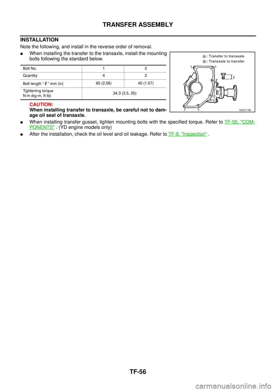
�When installing the transfer to the transaxle, install the mounting
bolts following the standard below.
CAUTION:
When installing transfer to transaxle, be careful not to dam-
age oil seal of transaxle.
�When installing transfer gusset, tighten mounting bolts with the specified torque. Refer to TF-55, "COM-
PONENTS" . (YD engine models only)
�After the installation, check the oil level and oil leakage. Refer to TF-9, "Inspection" .
Bolt No. 1 2
Quantity 4 2
Bolt length “ ” mm (in)65 (2.56) 40 (1.57)
Tightening torque
N·m (kg-m, ft-lb)34.3 (3.5, 25)
SDIA1178E
Page 2668 of 4179

RFD-8
DIFFERENTIAL GEAR OIL
DIFFERENTIAL GEAR OILPFP:KLD30
Changing Differential Gear OilEDS0027G
DRAINING
1. Stop engine.
2. Remove drain plug and drain oil.
3. Set a gasket on drain plug and install it to final drive assembly
and tighten to the specified torque. Refer to RFD-16, "
Compo-
nents" .
CAUTION:
Do not reuse gasket.
FILLING
1. Remove filler plug. Fill with new oil until oil level reaches the
specified level near filler plug mounting hole.
2. After refilling oil, check oil level. Set a gasket to filler plug, then
install it to final drive assembly. Refer to RFD-16, "
Components"
.
CAUTION:
Do not reuse gasket.
Checking Differential Gear OilEDS0027H
OIL LEAKAGE AND OIL LEVEL
�Make sure that oil is not leaking from final drive assembly or around it.
�Check oil level from filler plug mounting hole as shown in the fig-
ure.
CAUTION:
Do not start engine while checking oil level.
�Set a gasket on filler plug and install it on final drive assembly.
Refer to RFD-16, "
Components" .
CAUTION:
Do not reuse gasket.
PDIA0454E
Oil grade and Viscosity:
Refer to MA-17, "
Fluids and Lubricants" .
Oil capacity:
Approx. 0.55 (1 Imp pt)
PDIA0453E
PDIA0453E
Page 2696 of 4179

FAX-2
PRECAUTIONS
PRECAUTIONSPFP:00001
CautionEDS0005P
�When installing rubber parts, final tightening must be carried out under unladen condition* with tires on
ground.
�Oil will shorten the life of rubber bushes. Be sure to wipe off any spilled oil.
*: Fuel, radiator coolant and engine oil full. Spare tire, jack, hand tools and mats in designated positions.
�After installing removed suspension parts, check wheel alignment and adjust if necessary.
Observe the following precautions when disassembling and servicing drive shaft.
�Perform work in a location which is as dust-free as possible.
�Before disassembling and servicing, clean the outside of parts.
�Prevention of the entry of foreign objects must be taken into account during disassembly of the service
location.
�Disassembled parts must be carefully reassembled in the correct order. If work is interrupted, a clean
cover must be placed over parts.
�Paper shop cloths must be used. Fabric shop cloths must not be used because of the danger of lint adher-
ing to parts.
�Disassembled parts (except for rubber parts) should be cleaned with kerosene which shall be removed by
blowing with air or wiping with paper shop cloths.
Page 2706 of 4179

FAX-12
FRONT DRIVE SHAFT
×: Applicable
–: Not applicable
�Remove installation bolts from right-side drive shaft support bearing bracket. Then remove bracket from
engine.
�Remove installation bolts from right-side drive shaft and remove drive shaft from side shaft.
INSPECTION AFTER REMOVAL
�Move joint in up/down, left/right, and axial directions. Check for
motion that is not smooth and for significant looseness.
�Check for cracking and damage of boots, and for grease leak-
age.
INSTALLATION
�Install support bearing bracket onto engine and tighten installation bolts to specified torque. Refer to FA X -
11 , "Removal and Installation" .
�Install drive shaft to side shaft and tighten installation bolts to specified torque. Refer to FA X - 11 , "Removal
and Installation" .
1. In order to prevent damage to differential side oil seal, first fit a
protector onto oil seal before inserting drive shaft. Slide drive
shaft slide joint and tap with a hammer to install securely.
CAUTION:
Be sure to check that circular clip is securely fastened.
2. Insert drive shaft into steering knuckle. Install lock nut and then
temporarily tighten lock nut. Refer to FA X - 11 , "
Removal and
Installation" .
3. Install installation bolts for steering knuckle and strut.
4. Use lock plate to fix brake hose to strut.
5. Install tie rod to steering knuckle.
6. Install wheel sensor.
7. Tighten lock nuts to specified torque. Refer to FAX-11, "
Removal
and Installation" .
8. Install cotter pin.
CAUTION:
Discard the old cotter pin; replace with a new one.
Engine typeDrive shaft with circular clip
Right Left
QR20DE and QR25DE –×
YD22DDTi –×
RAA0030D
Model type Protector SST No.
RH KV38107800
LH KV38105500
SDIA0593E
SDIA0603E
Page 2716 of 4179

RAX-2
PRECAUTIONS
PRECAUTIONSPFP:00001
CautionEDS00060
�When installing rubber parts, final tightening must be carried out under unladen condition* with tires on
ground.
*: Fuel, radiator coolant and engine oil full. Spare tire, jack, hand tools and mats in designated positions.
�After installing removed suspension parts, check wheel alignment and adjust if necessary.
Observe the following precautions when disassembling and servicing drive shaft.
�Perform work in a location which is as dust-free and dirt-free as possible.
�Before disassembling and servicing, clean the outside of parts.
�The disassembly and service location must be clean. Care must be taken to prevent parts from becoming
dirty and to prevent the entry of foreign objects.
�Disassembled parts must be carefully reassembled in the correct order. If work is interrupted, a clean
cover must be placed over parts.
�Paper shop cloths must be used. Fabric shop cloths must not be used because of the danger of lint adher-
ing to parts.
�Disassembled parts (except for rubber parts) should be cleaned with kerosene which shall be removed by
blowing with air or wiping with paper shop cloths.
Page 2742 of 4179

FSU-12
FRONT SUSPENSION MEMBER
FRONT SUSPENSION MEMBERPFP:54401
Removal and InstallationEES00078
REMOVAL
1. Remove tyre. Raise vehicle.
2. Remove mounting nut on lower portion of stabilizer connecting rod from transverse link.
3. Remove transverse link from suspension member, and move the transverse link outward.
4. Remove front exhaust tube mounting rubber from suspension member.
5. Support engine or transmission with a jack.
6. Remove center member from vehicle. Refer to TF-55, "
TRANSFER ASSEMBLY"
7. Remove steering gear mounting bolts. Remove steering gear and power steering tube bracket from sus-
pension member.
8. Hang steering gear.
9. Remove rear engine mount insulator from suspension member.
10. Remove body-side mounting bolts from member pin stay.
11. Set a jack under suspension member, and remove suspension member mounting nuts.
12. Slowly lower jack to remove suspension member from vehicle.
INSTALLATION
�Refer to FSU-5, "Components" for tightening torque in the reverse order of removal.
�After installation, perform final tightening of each part under unladen conditions with tyre on ground.
Check wheel alignment. Refer to FSU-6, "
Wheel Alignment" .
Page 2743 of 4179

FSU-13
C
D
F
G
H
I
J
K
L
MA
B
FSU
SERVICE DATA AND SPECIFICATIONS (SDS)PFP:00030
General SpecificationEES000J6
Wheel Alignment (Unladen)EES00079
: Fuel, radiato")
SERVICE DATA AND SPECIFICATIONS (SDS)
FSU-13
C
D
F
G
H
I
J
K
L
MA
B
FSU
SERVICE DATA AND SPECIFICATIONS (SDS)PFP:00030
General SpecificationEES000J6
Wheel Alignment (Unladen)EES00079
: Fuel, radiator coolant and engine oil full. Spare tire, jack, hand tools and mats in designated positions.
Ball JointEES0007A
Wheelarch Height (Unladen)EES000J9
Suspension type Independent Macpherson strut
Shock absorber type Double-acting hydraulic
Stabilizer bar Standard equipment
Drive type4WD
Engine type QR20DE and QR25DE YD22DDTi
Camber
Degree minute (Decimal degree)Minimum – 0°54′ (– 0.9°)
Nominal – 0°24′ (– 0.4°)
Maximum 0°36′ (0.6°)
Left and right difference 45′ (0.75°)
Caster
Degree minute (Decimal degree)Minimum 1°42′ (1.7°)
Nominal 2°27′ (2.45°)
Maximum 3°12′ (3.2°)
Left and right difference 45′ (0.75°)
Kingpin offset
Degree minute (Decimal degree)Minimum 12°06′ (12.1°)
Nominal 13°30′ (13.5°)
Maximum 13°36′ (13.6°)
Total toe-in
Distance (A - B)Minimum 0 mm (0 in)
Nominal 1 mm (0.04 in)
Maximum 2 mm (0.08 in)
Wheel turning angel Refer to PS-42, "
Steering Angle" .
Swing torque 0.5 - 3.4 N·m (0.05 - 0.35 kg-m, 5 - 30 in-lb)
Measurement on spring balance (cotter pinhole position) 7.94 - 53.97 N (0.81 - 5.50 kg, 1.79 - 12.2 lb)
Turning torque 0.5 - 3.4 N·m (0.05 - 0.35 kg-m, 5 - 30 in-lb)
Axial endplay 0.1 mm (0.004 in) or less
Applied model QR20DE and QR25DE engine YD22DDTi engine
215/70R15 and 215/65R16 215/65R16
Front (Hf) 773 mm (30.43 in) 771 mm (30.35 in)
Rear (Hr) 786 mm (30.94 in) 785 mm (30.91 in)
SFA818A
Page 2744 of 4179
FSU-14
SERVICE DATA AND SPECIFICATIONS (SDS)
: Fuel, radiator coolant and engine oil full. Spare tire, jack, hand tools and mats in designated positions.

: Fuel, radiator coolant and engine oil full. Spare tire, jack, hand tools and mats in designated positions.")