Page 2432 of 4179
![NISSAN X-TRAIL 2003 Service Repair Manual AT-396
[ALL]
MAIN POWER SUPPLY AND GROUND CIRCUIT
TERMINALS AND REFERENCE VALUE MEASURED BETWEEN EACH TERMINAL
Diagnostic ProcedureECS004TI
1. CHECK TCM POWER SOURCE
1. Turn ignition switch to ON.](/manual-img/5/57404/w960_57404-2431.png "NISSAN X-TRAIL 2003 Service Repair Manual AT-396
[ALL]
MAIN POWER SUPPLY AND GROUND CIRCUIT
TERMINALS AND REFERENCE VALUE MEASURED BETWEEN EACH TERMINAL
Diagnostic ProcedureECS004TI
1. CHECK TCM POWER SOURCE
1. Turn ignition switch to ON.")
AT-396
[ALL]
MAIN POWER SUPPLY AND GROUND CIRCUIT
TERMINALS AND REFERENCE VALUE MEASURED BETWEEN EACH TERMINAL
Diagnostic ProcedureECS004TI
1. CHECK TCM POWER SOURCE
1. Turn ignition switch to ON. (Do not start engine.)
2. Check voltage between TCM terminals 10, 19, 28 and ground.
3. Turn ignition switch to OFF.
4. Check voltage between TCM terminal 10, 19, 28 and ground.
OK or NG
OK >> GO TO 3.
NG >> GO TO 2.
2. DETECT MALFUNCTIONING ITEM
Check the following items:
�Harness for short or open between ignition switch and TCM terminals 10, 19 and 28
�Fuse
�Ignition switch
Refer to “PG-2, "
POWER SUPPLY ROUTING" , “POWER SUPPLY ROUTING”.
OK or NG
OK >> GO TO 4
NG >> Repair or replace damaged parts.
Te r m i -
nal No.Wire color Item ConditionJudgement stan-
dard
(Approx.)
10 BR/W Power source
or When turning ignition switch to “ON”. Battery voltage
When turning ignition switch to
“OFF”.0V
19 BR/W Power source Same as No. 10
25 B/W Ground Always 0V
28 LPower source
(Memory back-up)Always Battery voltage
48 B/W Ground Always 0V
Name Connec-
tor No. Terminal
No. (Wire
color)Judgement standard (Approx.)
Power source F4610 (BR/W) Battery voltage
19 (BR/W) Battery voltage
Power source
(Memory back-up)F47 28 (L) Battery voltage
SCIA0713E
Name Connec-
tor No. Terminal No.
(Wire color)Judgement standard
(Approx.)
Power source F4610 (BR/W) 0V
19 (BR/W) 0V
Power source
(Memory back-up)F47 28 (L) Battery voltage
SCIA2657E
Page 2436 of 4179
![NISSAN X-TRAIL 2003 Service Repair Manual AT-400
[ALL]
A/T SHIFT LOCK SYSTEM
Diagnostic ProcedureECS00408
SYMPTOM 1:
�Selector lever cannot be moved from “P” position with key in ON position and brake pedal
applied.
�Selector lever can](/manual-img/5/57404/w960_57404-2435.png "NISSAN X-TRAIL 2003 Service Repair Manual AT-400
[ALL]
A/T SHIFT LOCK SYSTEM
Diagnostic ProcedureECS00408
SYMPTOM 1:
�Selector lever cannot be moved from “P” position with key in ON position and brake pedal
applied.
�Selector lever can")
AT-400
[ALL]
A/T SHIFT LOCK SYSTEM
Diagnostic ProcedureECS00408
SYMPTOM 1:
�Selector lever cannot be moved from “P” position with key in ON position and brake pedal
applied.
�Selector lever can be moved from “P” position with key in ON position and brake pedal released.
�Selector lever can be moved from “P” position when key is removed from key cylinder.
SYMPTOM 2:
�Ignition key cannot be removed when selector lever is set to “P” position.
�Ignition key can be removed when selector lever is set to any position except “P”.
1. CHECK KEY INTERLOCK CABLE
Check key interlock cable for damage.
OK or NG
OK >> GO TO 2.
NG >> Repair key interlock cable. Refer to AT- 4 0 2 , "
KEY INTERLOCK CABLE" .
2. CHECK SELECTOR LEVER POSITION
Check selector lever position for damage.
OK or NG
OK >> GO TO 3.
NG >> Check selector lever. Refer to AT- 4 0 9 , "
Park/Neutral Position (PNP) Switch Adjustment" .
3. CHECK SHIFT LOCK SOLENOID AND PARK POSITION SWITCH
1. Turn ignition switch to ON. (Do not start engine.)
2. Selector lever is set in P position.
3. Check operation sound.
OK or NG
OK >>INSPECTION END
NG >> GO TO 4.
4. CHECK POWER SOURCE
1. Turn ignition switch to ON. (Do not start engine.)
2. Check voltage between A/T device harness connector M58 ter-
minal 5 (P) and ground.
OK or NG
OK >> GO TO 7.
NG >> GO TO 5.
Condition Brake pedal Operation sound
When ignition switch is turned to
“ON” position and selector lever
is set in “P” position.Depressed Yes
Released No
Voltage:
Brake pedal depressed:
Battery voltage
Brake pedal released:
0V
SCIA5337E
Page 2444 of 4179
AT-408
[ALL]
ON-VEHICLE SERVICE
Park/Neutral Position (PNP) SwitchECS00CRB
COMPONENTS
REMOVAL AND INSTALLATION
Removal
1. Set select lever in N position.
2. Remove front tire LH from vehicle.
3. Remove LH splash guard. (Front fender side) Refer to EI-21, "
Removal and Installation" .
4. Remove engine under cover.
5. Remove control cable end from manual shaft.
6. Remove PNP switch fixing bolts.
7. Remove PNP switch from transaxle assembly.
Installation
Note the following, and install in the reverse order of removal.
�Align PNP switch position when installing.
1. Transaxle assembly 2. PNP switch
SCIA4855E
SCIA3156E
SCIA3154E
Page 2449 of 4179
![NISSAN X-TRAIL 2003 Service Repair Manual REMOVAL AND INSTALLATION
AT-413
[ALL]
D
E
F
G
H
I
J
K
L
MA
B
AT
REMOVAL AND INSTALLATIONPFP:00000
RemovalECS004NC
COMPONENTS
CAUTION:
Before separating transaxle from engine, remove the crankshaft p](/manual-img/5/57404/w960_57404-2448.png "NISSAN X-TRAIL 2003 Service Repair Manual REMOVAL AND INSTALLATION
AT-413
[ALL]
D
E
F
G
H
I
J
K
L
MA
B
AT
REMOVAL AND INSTALLATIONPFP:00000
RemovalECS004NC
COMPONENTS
CAUTION:
Before separating transaxle from engine, remove the crankshaft p")
REMOVAL AND INSTALLATION
AT-413
[ALL]
D
E
F
G
H
I
J
K
L
MA
B
AT
REMOVAL AND INSTALLATIONPFP:00000
RemovalECS004NC
COMPONENTS
CAUTION:
Before separating transaxle from engine, remove the crankshaft position sensor (Euro-OBD) from
transaxle. Be careful not to damage sensor.
1. Remove battery and bracket, air cleaner and air duct.
2. Remove air breather hose.
3. Disconnect terminal cord assembly harness connector, PNP switch harness connector and revolution
sensor harness connector.
4. Remove crankshaft position sensor (Euro-OBD) from transaxle.
5. Disconnect control cable from transaxle.
6. Remove front exhaust tube. Refer to EX-2, "
Removal and Installation"
7. Disconnect A/T fluid cooler hoses.
8. Remove drive shafts. Refer to FAX-11, "
FRONT DRIVE SHAFT" , RAX-10, "REAR DRIVE SHAFT" .
9. Remove transfer assembly. Refer to TF-55, "
Removal and Installation" .
10. Remove starter motor from transaxle. Refer to SC-25, "
Removal and Installation" .
11. Support transaxle with a transmission jack.
1. Transfer assembly 2. A/T fluid level gauge 3. A/T fluid charging pipe
4. O-ring 5. Center member 6. Front engine mounting insulator
7. Grommet 8. Fluid cooler tube 9. Fluid cooler tube
10. Copper washer 11. Copper washer 12. Transaxle assembly
13. Stopper 14. LH engine mounting insulator
SCIA5739E
Page 2450 of 4179
AT-414
[ALL]
REMOVAL AND INSTALLATION
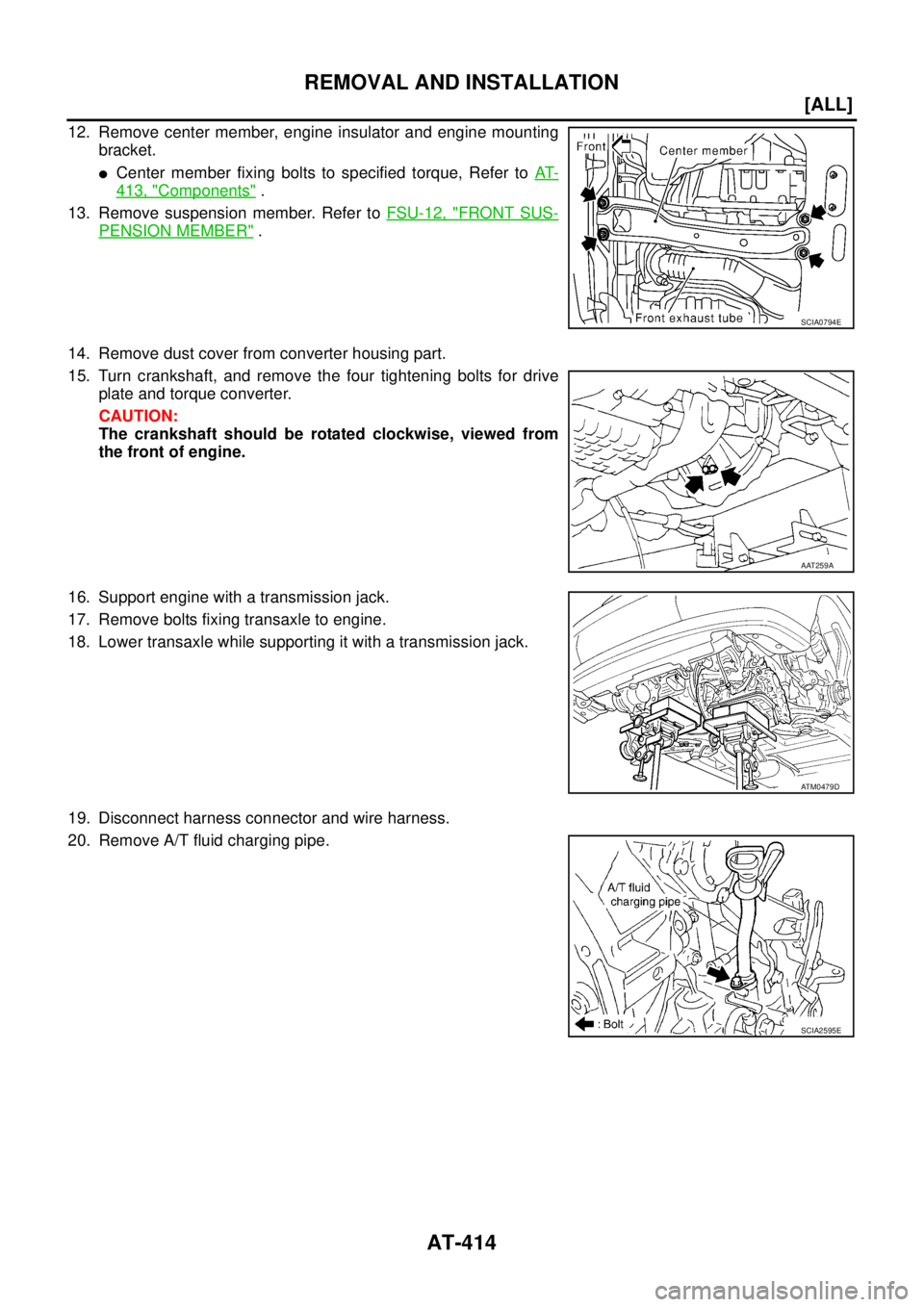
12. Remove center member, engine insulator and engine mounting
bracket.
�Center member fixing bolts to specified torque, Refer to AT-
413, "Components" .
13. Remove suspension member. Refer to FSU-12, "
FRONT SUS-
PENSION MEMBER" .
14. Remove dust cover from converter housing part.
15. Turn crankshaft, and remove the four tightening bolts for drive
plate and torque converter.
CAUTION:
The crankshaft should be rotated clockwise, viewed from
the front of engine.
16. Support engine with a transmission jack.
17. Remove bolts fixing transaxle to engine.
18. Lower transaxle while supporting it with a transmission jack.
19. Disconnect harness connector and wire harness.
20. Remove A/T fluid charging pipe.
SCIA0794E
AAT259A
ATM0479D
SCIA2595E
Page 2451 of 4179
![NISSAN X-TRAIL 2003 Service Repair Manual REMOVAL AND INSTALLATION
AT-415
[ALL]
D
E
F
G
H
I
J
K
L
MA
B
AT
21. Remove fluid cooler tube.
INSPECTION
Installation and inspection of torque converter
� After inserting a torque converter to a tra](/manual-img/5/57404/w960_57404-2450.png "NISSAN X-TRAIL 2003 Service Repair Manual REMOVAL AND INSTALLATION
AT-415
[ALL]
D
E
F
G
H
I
J
K
L
MA
B
AT
21. Remove fluid cooler tube.
INSPECTION
Installation and inspection of torque converter
� After inserting a torque converter to a tra")
REMOVAL AND INSTALLATION
AT-415
[ALL]
D
E
F
G
H
I
J
K
L
MA
B
AT
21. Remove fluid cooler tube.
INSPECTION
Installation and inspection of torque converter
� After inserting a torque converter to a transaxle, be sure to
check distance “A” to ensure it is within the reference value limit.
InstallationECS004ND
Install the removed parts in the reverse order of the removal, while paying attention to the following work.
�When installing transaxle to the engine, attach the fixing bolts in
accordance with the following standard.
�Align the positions of tightening bolts for drive plate with those of
the torque converter, and temporarily tighten the bolts. Then,
tighten the bolts to the specified torque. Refer to AT- 4 1 6 , "
Com-
ponents" .
CAUTION:
�When turning crankshaft, turn it clockwise as viewed from
the front of the engine.
�When tightening the tightening bolts for the torque con-
verter after fixing the crankshaft pulley bolts, be sure to
confirm the tightening torque of the crankshaft pulley
mounting bolts.
� After converter is installed to drive plate, rotate crankshaft
several turns and check to be sure that transaxle rotates freely without binding.
�After completing installation, check for fluid leakage, fluid level, and the positions of A/T. Refer to AT- 1 6 ,
"Checking A/T Fluid" , AT- 4 0 9 , "Control Cable Adjustment" .
SCIA2596E
Distance “A”
QR20DE models: 19.0 mm (0.75 in) or more
QR25DE models: 14.0 mm (0.55 in) or more
SAT573D
Bolt No.Tightening torque
N·m (kg-m, ft-lb)Bolt length “ L ”
mm (in)
1
75 (7.7, 55)49 (1.93)
2 45 (1.77)
3
43 (4.4, 32)40 (1.57)
4 30 (1.18)
5
36 (3.7, 27)40 (1.57)
6 45 (1.97)
SCIA0795E
SCIA3138E
Page 2566 of 4179
![NISSAN X-TRAIL 2003 Service Repair Manual AT-530
[ALL]
SERVICE DATA AND SPECIFICATIONS (SDS)
SERVICE DATA AND SPECIFICATIONS (SDS)PFP:00030
General SpecificationsECS00CXK
*1: Refer to MA-17, "Fluids and Lubricants" .
Shift ScheduleECS00CXL](/manual-img/5/57404/w960_57404-2565.png "NISSAN X-TRAIL 2003 Service Repair Manual AT-530
[ALL]
SERVICE DATA AND SPECIFICATIONS (SDS)
SERVICE DATA AND SPECIFICATIONS (SDS)PFP:00030
General SpecificationsECS00CXK
*1: Refer to MA-17, \"Fluids and Lubricants\" .
Shift ScheduleECS00CXL")
AT-530
[ALL]
SERVICE DATA AND SPECIFICATIONS (SDS)
SERVICE DATA AND SPECIFICATIONS (SDS)PFP:00030
General SpecificationsECS00CXK
*1: Refer to MA-17, "Fluids and Lubricants" .
Shift ScheduleECS00CXL
VEHICLE SPEED WHEN SHIFTING GEARS AND THROTTLE POSITION
For 85X23 model
For 85X64 model
VEHICLE SPEED WHEN PERFORMING LOCK-UP
Unit: km/h (MPH)
NOTE:
�Lock-up vehicle speed indicates the speed in D4 position.
�Perform lock-up inspection after warming up engine.
�Lock-up vehicle speed may vary depending on the driving conditions and circumstances. EngineQR20DE QR25DE
Automatic transaxle model RE4F04B (4WD)
Automatic transaxle assembly Model code number 85X23 85X64
Transaxle gear ratio1st 2.785
2nd 1.545
3rd 1.000
4th 0.694
Reverse 2.272
Final drive 4.425 4.087
Recommended fluid Genuine Nissan ATF or equiualent*1
Fluid capacity (Imp qt)8.5 (7-1/2)
Throttle posi-
tionShift patternVehicle speed km/h (MPH)
D
1 → D2D2 → D3D3 → D4D4 → D3D3 → D2D2 → D1
Full throttleComfort53 - 61
(33 - 38)99 - 107
(62 - 67)156 - 164
(97 - 102)152 - 160
(94 - 99)89 - 97
(53 - 60)41 - 49
(25 - 30)
Auto power53 - 61
(33 - 38)99 - 107
(62 - 67)156 - 164
(97 - 102)152 - 160
(94 - 99)89 - 97
(55 - 60)41 - 49
(25 - 30)
Half throttleComfort34 - 42
(21 - 26)64 - 72
(40 - 45)124 - 138
(77 - 82)82 - 90
(51 - 56)41 - 49
(25 - 30)5 - 13
(3 - 8)
Auto power38 - 46
(24 - 29)70 - 78
(44 - 48)124 - 132
(77 - 82)81 - 89
(50 - 55)44 - 53
(27 - 33)5 - 13
(3 - 8)
Throttle posi-
tionShift patternVehicle speed km/h (MPH)
D
1 → D2D2 → D3D3 → D4D4 → D3D3 → D2D2 → D1
Full throttleComfort57 - 65
(35 - 40)107 - 115
(66 - 71)167 - 175
(104 - 109)163 - 171
(101 - 106)97 - 105
(60 - 65)41 - 49
(25 - 30)
Auto power57 - 65
(35 - 40)107 - 115
(66 - 71)167 - 175
(104 - 109)163 - 171
(101 - 106)97 - 105
(60 - 65)41 - 49
(25 - 30)
Half throttleComfort36 - 44
(22 - 27)71 - 79
(44 - 49)131 - 139
(81 - 86)77 - 85
(48 - 53)38 - 46
(23 - 28)5 - 13
(3 - 8)
Auto power42 - 50
(26 - 31)79 - 87
(49 - 54)131 - 139
(81 - 86)77 - 85
(48 - 53)45 - 53
(28 - 33)5 - 13
(3 - 8)
Model code No. 85X23 85X64
Vehicle speed Throttle position 1/8 58 - 66 (36 - 41) 61 - 69 (38 - 43)
Page 2567 of 4179
![NISSAN X-TRAIL 2003 Service Repair Manual SERVICE DATA AND SPECIFICATIONS (SDS)
AT-531
[ALL]
D
E
F
G
H
I
J
K
L
MA
B
AT
Stall RevolutionECS00CXM
Line PressureECS00F1T
Control ValvesECS00F1U
CONTROL VALVE AND PLUG RETURN SPRINGS
For 85X23 mod](/manual-img/5/57404/w960_57404-2566.png "NISSAN X-TRAIL 2003 Service Repair Manual SERVICE DATA AND SPECIFICATIONS (SDS)
AT-531
[ALL]
D
E
F
G
H
I
J
K
L
MA
B
AT
Stall RevolutionECS00CXM
Line PressureECS00F1T
Control ValvesECS00F1U
CONTROL VALVE AND PLUG RETURN SPRINGS
For 85X23 mod")
SERVICE DATA AND SPECIFICATIONS (SDS)
AT-531
[ALL]
D
E
F
G
H
I
J
K
L
MA
B
AT
Stall RevolutionECS00CXM
Line PressureECS00F1T
Control ValvesECS00F1U
CONTROL VALVE AND PLUG RETURN SPRINGS
For 85X23 model
Unit: mm (in)
*: Always check with the Parts Department for the latest parts information.EngineStall revolution
rpm
QR20DE 2,450 - 2,950
QR25DE 2,300 - 2,750
Engine speed
rpmLine pressure kPa (kg/cm2 , psi)
D, 2 and 1 positions R position
Idle 500 (5.1, 73) 778 (7.9, 113)
Stall 1,233 (12.6, 179) 1,918 (19.6, 278)
PartsItem
Part No.* Free length Outer diameter
Upper body7 Pilot valve spring 31742-3AX03 38.98 (1.535) 8.9 (0.350)
35 1-2 accumulator valve spring 31742-3AX00 20.5 (0.807) 6.95 (0.274)
10 1-2 accumulator piston spring 31742-85X02 55.60 (2.189) 19.6 (0.772)
17 1st reducing valve spring 31742-80X05 27.0 (1.063) 7.0 (0.276)
19 3-2 timing valve spring 31736-01X00 23.0 (0.906) 6.65 (0.262)
24 Overrun clutch reducing valve spring 31742-80X15 37.5 (1.476) 6.9 (0.272)
26 Torque converter relief valve spring 31742-80X07 31.0 (1.220) 9.0 (0.354)
31 Torque converter clutch control valve 31742-85X00 56.98 (2.243) 6.5 (0.256)
3 Cooler check valve spring 31742-85X01 29.4 (1.157) 6.0 (0.236)
Lower body11 Pressure regulator valve spring 31742-80X13 45.0 (1.772) 15.0 (0.591)
16 Overrun clutch control valve spring 31762-80X00 21.7 (0.854) 7.0 (0.276)
20 Accumulator control valve spring 31742-80X02 22.0 (0.866) 6.5 (0.256)
25 Shift valve A spring 31762-80X00 21.7 (0.854) 7.0 (0.276)
30 Shuttle valve spring 31762-41X04 51.0 (2.008) 5.65 (0.222)
32 Shift valve B spring 31762-80X00 21.7 (0.854) 7.0 (0.276)
2 Pressure modifier piston spring 31742-41X15 30.5 (1.201) 9.8 (0.386)
6 Pressure modifier valve spring 31742-80X16 32.0 (1.260) 6.9 (0.272)
— Oil cooler relief valve spring 31872-31X00 17.02 (0.670) 8.0 (0.315)
![NISSAN X-TRAIL 2003 Service Repair Manual AT-408
[ALL]
ON-VEHICLE SERVICE
Park/Neutral Position (PNP) SwitchECS00CRB
COMPONENTS
REMOVAL AND INSTALLATION
Removal
1. Set select lever in N position.
2. Remove front tire LH from vehicle.
3. Rem](/manual-img/5/57404/w960_57404-2443.png "NISSAN X-TRAIL 2003 Service Repair Manual AT-408
[ALL]
ON-VEHICLE SERVICE
Park/Neutral Position (PNP) SwitchECS00CRB
COMPONENTS
REMOVAL AND INSTALLATION
Removal
1. Set select lever in N position.
2. Remove front tire LH from vehicle.
3. Rem")