Page 2430 of 4179
![NISSAN X-TRAIL 2003 Service Repair Manual AT-394
[ALL]
MAIN POWER SUPPLY AND GROUND CIRCUIT
MAIN POWER SUPPLY AND GROUND CIRCUITPFP:00100
DescriptionECS00CS1
When the power supply to the TCM is cut OFF, for example because the battery is re NISSAN X-TRAIL 2003 Service Repair Manual AT-394
[ALL]
MAIN POWER SUPPLY AND GROUND CIRCUIT
MAIN POWER SUPPLY AND GROUND CIRCUITPFP:00100
DescriptionECS00CS1
When the power supply to the TCM is cut OFF, for example because the battery is re](/manual-img/5/57404/w960_57404-2429.png)
AT-394
[ALL]
MAIN POWER SUPPLY AND GROUND CIRCUIT
MAIN POWER SUPPLY AND GROUND CIRCUITPFP:00100
DescriptionECS00CS1
When the power supply to the TCM is cut OFF, for example because the battery is removed, and the self-diag-
nostics memory function stops, malfunction is detected.
On Board Diagnosis LogicECS00CS2
�Diagnostic trouble code “INITIAL START” with CONSULT-II is detected when TCM dose not receive the
voltage signal from the battery power supply.
�This is not a malfunction message. (Whenever shutting “OFF” a power supply to the TCM, this message
appears on the screen.)
Possible CauseECS00CS3
Harness or connector
(Battery or ignition switch and TCM circuit is open or shorted.)
DTC Confirmation ProcedureECS00CS4
NOTE:
If “DTC Confirmation Procedure” has been previously performed, always turn ignition switch “OFF”
and wait at least 10 seconds before performing the next test.
WITH CONSULT-II
1. Turn ignition switch ON. (Do not start engine.)
2. Select “DATA MONITOR” mode for “A/T” with CONSULT-II.
3. Wait for at least 2 consecutive seconds.
4. If DTC is detected, go to AT- 3 9 6 , "
Diagnostic Procedure" .
SAT014K
Page 2438 of 4179
AT-402
[ALL]
KEY INTERLOCK CABLE
KEY INTERLOCK CABLEPFP:34908
ComponentsECS00409
CAUTION:
�Install key interlock cable in such a way that it will not be damaged by sharp bends, twists or inter-
ference with adjacent parts.
�After installing key interlock cable to control device, make sure that casing cap and bracket are
firmly secured in their positions.
RemovalECS0040A
1. Unlock slider by squeezing lock tabs on slider from adjuster
holder and remove interlock rod from cable.
SAT996J
SAT853J
Page 2467 of 4179
DISASSEMBLY
AT-431
[ALL]
D
E
F
G
H
I
J
K
L
MA
B
AT
�To prevent brake linings from cracking or peeling, do not
stretch the flexible band unnecessarily. When removing
the brake band, always secure it with a clip as shown in
the right figure.
Leave the clip in position after removing the brake band.
c. Check brake band facing for damage, cracks, wear or burns.
33. Remove input shaft assembly (high clutch assembly) and reverse clutch assembly according to the follow-
ing procedures.
a. Remove input shaft assembly (high clutch assembly) with
reverse clutch assembly.
b. Remove input shaft assembly (high clutch assembly) from
reverse clutch.
SAT039D
SAT040D
SCIA4009E
SCIA4010E
Page 2605 of 4179

TROUBLE DIAGNOSIS
TF-29
C
E
F
G
H
I
J
K
L
MA
B
TF
*: The values are changed by throttle opening and engine speed.
CONSULT-II FunctionEDS001VL
FUNCTION
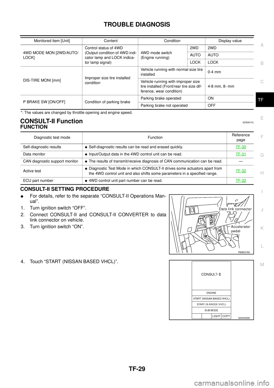
CONSULT-II SETTING PROCEDURE
�For details, refer to the separate “CONSULT-II Operations Man-
ual”.
1. Turn ignition switch “OFF”.
2. Connect CONSULT-II and CONSULT-II CONVERTER to data
link connector on vehicle.
3. Turn ignition switch “ON”.
4. Touch “START (NISSAN BASED VHCL)”.
4WD MODE MON [2WD/AUTO/
LOCK]Control status of 4WD
(Output condition of 4WD indi-
cator lamp and LOCK indica-
tor lamp signal)4WD mode switch
(Engine running)2WD 2WD
AUTO AUTO
LOCK LOCK
DIS-TIRE MONI [mm]Improper size tire installed
conditionVehicle running with normal size tire
installed0-4 mm
Vehicle running with improper size
tire installed (Front/rear tire size dif-
ference, wear condition)4-8 mm, 8- mm
P BRAKE SW [ON/OFF] Condition of parking brakeParking brake operated ON
Parking brake not operated OFF Monitored item [Unit] Content Condition Display value
Diagnostic test mode FunctionReference
page
Self-diagnostic results
�Self-diagnostic results can be read and erased quickly.TF-30
Data monitor�Input/Output data in the 4WD control unit can be read.TF-31
CAN diagnostic support monitor�The results of transmit/receive diagnosis of CAN communication can be read. —
Active test
�Diagnostic Test Mode in which CONSULT-II drives some actuators apart from
the 4WD control unit and also shifts some parameters in a specified range.TF-32
ECU part number�4WD control unit part number can be read.TF-32
PBIB0376E
SAIA0450E
Page 2607 of 4179

TROUBLE DIAGNOSIS
TF-31
C
E
F
G
H
I
J
K
L
MA
B
TF
How to Erase Self-diagnostic Results
1. Perform applicably inspection of malfunctioning item and then repair or replace.
2. Start engine and drive at 30 km/h (19 MPH) or more for approx. 1 minute.
3. Make sure that ABS warning lamp turns OFF.
NOTE:
Make sure that ABS warning lamp turns OFF by driving for a minute at vehicle speed of 30 km/h
(19 MPH) or more after turning ignition switch "OFF" if 4WD warning lamp turns ON with system
malfunction of “ABS SYSTEM [C1203]”. 4WD warning lamp may not turn OFF if it is normal unless
ignition switch turns OFF at once and engine restarts after that.
4. Turn ignition switch “OFF” to erase memory.
5. Start engine and select “SELF-DIAG RESULTS” mode for “ALL MODE AWD/4WD” with CONSULT-II.
6. Touch “ERASE” on CONSULT-II screen to erase DTC memory.
CAUTION:
If memory cannot be erased, perform applicably diagnosis.
7. Drive at 30 km/h (19 MPH) or more for approx. 1 minute. Be sure 4WD warning lamp is OFF.
DATA MONITOR MODE
Operation Procedure
1. Perform “CONSULT-II SETTING PROCEDURE”. Refer to TF-29, "CONSULT-II SETTING PROCEDURE"
.
2. Touch “DATA MONITOR”.
3. Select from “SELECT MONITOR ITEM”, screen of data monitor mode is displayed.
NOTE:
When malfunction is detected, CONSULT-II performs REAL-TIME DIAGNOSIS.
Also, any malfunction detected while in this mode will be displayed at real time.
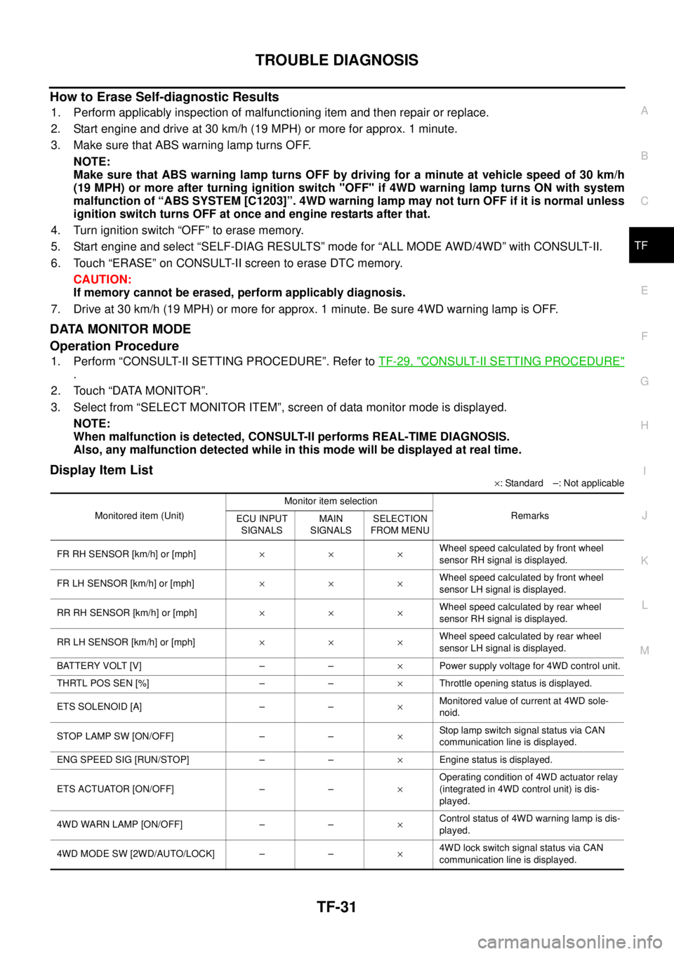
Display Item List
×: Standard –: Not applicable
Monitored item (Unit)Monitor item selection
Remarks
ECU INPUT
SIGNALSMAIN
SIGNALSSELECTION
FROM MENU
FR RH SENSOR [km/h] or [mph]×××Wheel speed calculated by front wheel
sensor RH signal is displayed.
FR LH SENSOR [km/h] or [mph]×××Wheel speed calculated by front wheel
sensor LH signal is displayed.
RR RH SENSOR [km/h] or [mph]×××Wheel speed calculated by rear wheel
sensor RH signal is displayed.
RR LH SENSOR [km/h] or [mph]×××Wheel speed calculated by rear wheel
sensor LH signal is displayed.
BATTERY VOLT [V] – –×Power supply voltage for 4WD control unit.
THRTL POS SEN [%] – –×Throttle opening status is displayed.
ETS SOLENOID [A] – –×Monitored value of current at 4WD sole-
noid.
STOP LAMP SW [ON/OFF] – –×Stop lamp switch signal status via CAN
communication line is displayed.
ENG SPEED SIG [RUN/STOP] – –×Engine status is displayed.
ETS ACTUATOR [ON/OFF] – –×Operating condition of 4WD actuator relay
(integrated in 4WD control unit) is dis-
played.
4WD WARN LAMP [ON/OFF] – –×Control status of 4WD warning lamp is dis-
played.
4WD MODE SW [2WD/AUTO/LOCK] – –×4WD lock switch signal status via CAN
communication line is displayed.
Page 2608 of 4179

TF-32
TROUBLE DIAGNOSIS
ACTIVE TEST MODE
Description
Use this mode to determine and identify the details of a malfunction based on self-diagnostic results or data
monitor. 4WD control unit gives drive signal to actuator with receiving command from CONSULT-II to check
operation of actuator.
Test Item
CAUTION:
Do not continuously energize for a long time.
4WD CONTROL UNIT PART NUMBER
Ignore the 4WD control unit part number displayed in the “ECU PART NUMBER”.
Refer to parts catalog to order the 4WD control unit.
4WD MODE MON [2WD/AUTO/LOCK] – –×Control status of 4WD is displayed.
(Output condition of 4WD LOCK indicator
lamp signal)
DIS-TIRE MONI [mm] – –×Improper size tire installed condition is dis-
played.
P BRAKE SW [ON/OFF] – –×Parking switch signal status via CAN com-
munication line is displayed.
Voltage [V] – –×The value measured by the voltage probe
is displayed.
Frequency [Hz] – –×
The value measured by the pulse probe is
displayed. DUTY-HI (high) [%] – –×
DUTY-LOW (low) [%] – –×
PLS WIDTH-HI [msec] – –×
PLS WIDTH-LOW [msec] – –× Monitored item (Unit)Monitor item selection
Remarks
ECU INPUT
SIGNALSMAIN
SIGNALSSELECTION
FROM MENU
Test item Condition Description
ETS S/V
(Detects 4WD solenoid)
�Vehicle stopped
�Engine running
�No DTC detected
�Change command current value to 4WD solenoid, and then change driv-
ing mode. (Monitor value is normal if it is within approximately ±10% of
command value.)
Qu: Increase current value in increments of 0.20A
Qd: Decrease current value in increments of 0.20A
UP: Increase current value in increments of 0.02A
DOWN: Decrease current value in increments of 0.02A
Page 2625 of 4179

TROUBLE DIAGNOSIS FOR SYMPTOMS
TF-49
C
E
F
G
H
I
J
K
L
MA
B
TF
4. CHECK SYSTEM FOR 4WD SOLENOID
Perform trouble diagnosis for 4WD solenoid system. Refer to TF-36, "
4WD Solenoid" .
OK or NG
OK >> GO TO 5.
NG >> Repair or replace damaged parts.
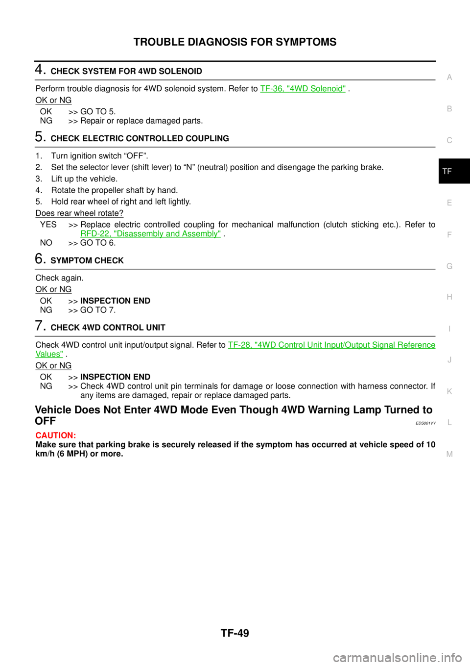
5. CHECK ELECTRIC CONTROLLED COUPLING
1. Turn ignition switch “OFF”.
2. Set the selector lever (shift lever) to “N” (neutral) position and disengage the parking brake.
3. Lift up the vehicle.
4. Rotate the propeller shaft by hand.
5. Hold rear wheel of right and left lightly.
Does rear wheel rotate?
YES >> Replace electric controlled coupling for mechanical malfunction (clutch sticking etc.). Refer to
RFD-22, "
Disassembly and Assembly" .
NO >> GO TO 6.
6. SYMPTOM CHECK
Check again.
OK or NG
OK >>INSPECTION END
NG >> GO TO 7.
7. CHECK 4WD CONTROL UNIT
Check 4WD control unit input/output signal. Refer to TF-28, "
4WD Control Unit Input/Output Signal Reference
Va l u e s" .
OK or NG
OK >>INSPECTION END
NG >> Check 4WD control unit pin terminals for damage or loose connection with harness connector. If
any items are damaged, repair or replace damaged parts.
Vehicle Does Not Enter 4WD Mode Even Though 4WD Warning Lamp Turned to
OFF
EDS001VY
CAUTION:
Make sure that parking brake is securely released if the symptom has occurred at vehicle speed of 10
km/h (6 MPH) or more.
Page 2674 of 4179
RFD-14
REAR FINAL DRIVE ASSEMBLY
REAR FINAL DRIVE ASSEMBLYPFP:38300
Removal and InstallationEDS001ZA
REMOVAL
1. Remove propeller shaft. Refer to PR-4, "Removal and Installation" .
2. Remove drive shaft with power tool. Refer to RAX-10, "
Removal and Installation" .
3. Disconnect electric controlled coupling connector.
4. Remove rear final drive breather hose and electric controlled coupling breather hose.
5. Support rear final drive assembly with a suitable jack.
6. Remove rear final drive mounting nut at rear suspension mem-
ber.
7. Remove rear final drive mounting bolts at final drive mounting
bracket, and then remove rear final drive assembly.
If necessary, remove final drive mounting bracket.
CAUTION:
Secure rear final drive assembly to a suitable jack while
removing it.
1. Rear suspension member 2. Final drive mounting bracket 3. Harness bracket
4. Drive shaft 5. Propeller shaft 6. Rear final drive assembly
PDIA0433E
PDIA0434E
PDIA0435E