Page 1886 of 4179
FL-8
[QR]
FUEL LEVEL SENSOR UNIT, FUEL FILTER AND FUEL PUMP ASSEMBLY
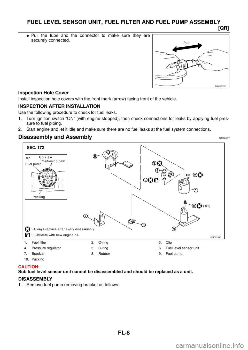
�Pull the tube and the connector to make sure they are
securely connected.
Inspection Hole Cover
Install inspection hole covers with the front mark (arrow) facing front of the vehicle.
INSPECTION AFTER INSTALLATION
Use the following procedure to check for fuel leaks.
1. Turn ignition switch “ON” (with engine stopped), then check connections for leaks by applying fuel pres-
sure to fuel piping.
2. Start engine and let it idle and make sure there are no fuel leaks at the fuel system connections.
Disassembly and AssemblyEBS00KOV
CAUTION:
Sub fuel level sensor unit cannot be disassembled and should be replaced as a unit.
DISASSEMBLY
1. Remove fuel pump removing bracket as follows:
PBIC1653E
1. Fuel filter 2. O-ring 3. Clip
4. Pressure regulator 5. O-ring 6. Fuel level sensor unit
7. Bracket 8. Rubber 9. Fuel pump
10. Packing
PBIC2259E
Page 1887 of 4179
![NISSAN X-TRAIL 2003 Service Repair Manual FUEL LEVEL SENSOR UNIT, FUEL FILTER AND FUEL PUMP ASSEMBLY
FL-9
[QR]
C
D
E
F
G
H
I
J
K
L
MA
FL
a. Using a screwdriver, separate the snap fit portion of bracket in
numerical order as shown in the fig](/manual-img/5/57404/w960_57404-1886.png "NISSAN X-TRAIL 2003 Service Repair Manual FUEL LEVEL SENSOR UNIT, FUEL FILTER AND FUEL PUMP ASSEMBLY
FL-9
[QR]
C
D
E
F
G
H
I
J
K
L
MA
FL
a. Using a screwdriver, separate the snap fit portion of bracket in
numerical order as shown in the fig")
FUEL LEVEL SENSOR UNIT, FUEL FILTER AND FUEL PUMP ASSEMBLY
FL-9
[QR]
C
D
E
F
G
H
I
J
K
L
MA
FL
a. Using a screwdriver, separate the snap fit portion of bracket in
numerical order as shown in the figure.
CAUTION:
Put cloth or similar one on the edge of screwdriver not to
damage the inserted portion.
b. Pull out fuel pump, and disconnect harness connector.
2. Separate fuel filter and fuel level sensor unit as follows:
a. Fit a used O-ring into space between fuel level sensor unit and
fuel filter to release tabs.
NOTE:
For reference when reassembling, put a mating mark on outer
edges of fuel level sensor unit and fuel filter with some means
which cannot be erased by fuel.
b. Insert screwdriver to the gap between fuel filter and fuel level
sensor unit to separate them.
CAUTION:
Put cloth or similar one on the edge of screwdriver not to
damage the inserted portion.
3. Remove pressure regulator from fuel filter as follows:
a. Open and remove the clip.
b. Pull pressure regulator straight out during removal.
CAUTION:
�Avoid impacts such as falling during removal.
�Do not disassemble or adjust.
ASSEMBLY
Note the following, and assemble in the reverse order of disassembly.
�Install fuel filter and fuel pump with the tabs aligned. Make sure a click sound of secure engagement is
heard.
�Securely connect harness connector of fuel pump.
�Install pressure regulator O-ring.
CAUTION:
�When replacing, always use new O-ring.
�Handle it with bare hands. (Do not use gloves.)
�Visually check the O-ring, mounting parts and mating parts for foreign materials and flaws.
�Before installing, apply new engine oil.
�To avid damage, do not apply an excessive force (pulling or starching).
PBIC0242E
PBIC0243E
PBIC0244E
Page 1888 of 4179
FL-10
[QR]
FUEL LEVEL SENSOR UNIT, FUEL FILTER AND FUEL PUMP ASSEMBLY
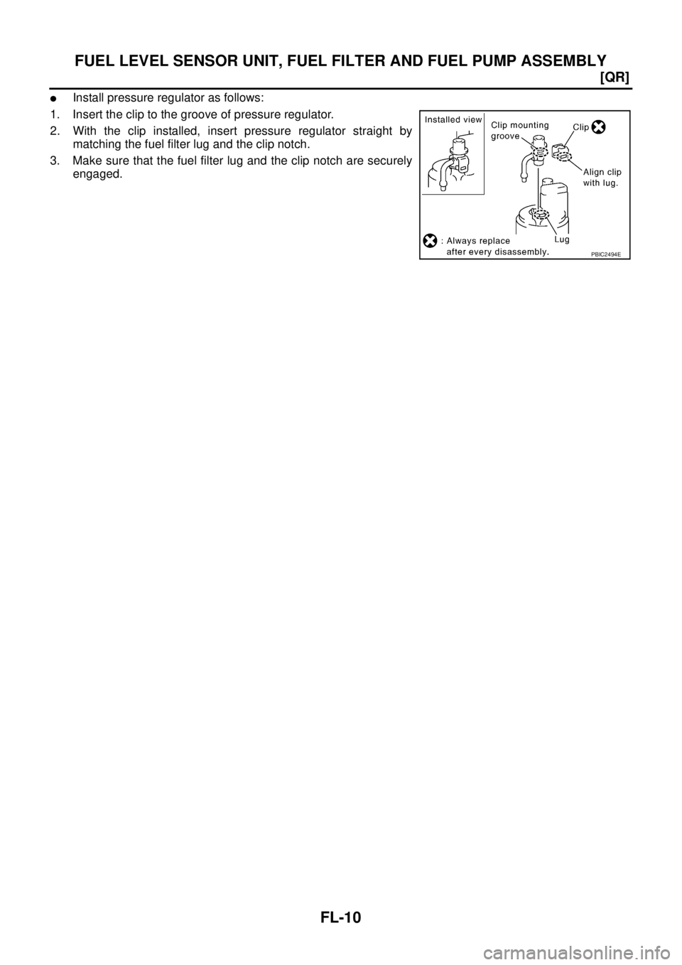
�Install pressure regulator as follows:
1. Insert the clip to the groove of pressure regulator.
2. With the clip installed, insert pressure regulator straight by
matching the fuel filter lug and the clip notch.
3. Make sure that the fuel filter lug and the clip notch are securely
engaged.
PBIC2494E
Page 1890 of 4179
![NISSAN X-TRAIL 2003 Service Repair Manual FL-12
[QR]
FUEL TANK
5. Using a transmission jack, support the bottom of final drive
assembly.
6. Remove mounting nuts on rear suspension member, and lower
the transmission jack carefully until just](/manual-img/5/57404/w960_57404-1889.png "NISSAN X-TRAIL 2003 Service Repair Manual FL-12
[QR]
FUEL TANK
5. Using a transmission jack, support the bottom of final drive
assembly.
6. Remove mounting nuts on rear suspension member, and lower
the transmission jack carefully until just")
FL-12
[QR]
FUEL TANK
5. Using a transmission jack, support the bottom of final drive
assembly.
6. Remove mounting nuts on rear suspension member, and lower
the transmission jack carefully until just before rear suspension
member is removed from stud bolts on the vehicle. Refer to
RSU-5, "
REAR SUSPENSION ASSEMBLY" .
7. Disconnect fuel filler hose, EVAP hose and vent hose at fuel
tank side.
�For disconnection procedure of quick connector on EVAP
hose, refer to FL-4, "
FUEL LEVEL SENSOR UNIT, FUEL FIL-
TER AND FUEL PUMP ASSEMBLY" .
8. Remove fuel tank protector.
9. Remove fuel tank band mounting bolts while supporting fuel
tank.
CAUTION:
Sustain the bottom of fuel tank by using plate or anything
same.
10. Remove fuel tank.
�After lifting down the front portion of fuel tank, remove fuel
tank by pulling it from the upper front of final drive assembly,
so that fuel tank can move forwardly.
CAUTION:
Pay attention not to fall fuel tank because it forwardly
inclines and becomes unstable.
NOTE:
It is desirable that more than two technicians work together.
INSTALLATION
Note the following, and install in the reverse order of removal.
�Surely clamp fuel hoses and insert hose to the length below.
�Be sure hose clamp is not placed on swelled area of fuel tube.
�Tighten fuel hose clamp so that the remaining length of screw thread becomes to the following.
�Fit fuel tank band pin to the vehicle side securely.
�Before fixing fuel tank, temporarily install fuel filler tube.
KBIA0285E
KBIA0286E
KBIA0290E
Fuel filler hose : 35mm (1.38 in)
The other hoses : 25mm (0.98 in)
Fuel tank side : 5 - 9 mm (0.20 - 0.35 in)
Fuel filler tube side : 7 - 11 mm (0.28 - 0.43 in)
Page 1894 of 4179
![NISSAN X-TRAIL 2003 Service Repair Manual FL-16
[YD22DDTi]
FUEL SYSTEM
FUEL SYSTEMPFP:17503
Checking Fuel LinesEBS00BKH
Inspect fuel lines, filler cap and tank for improper attachment, leaks,
cracks, damage, loose connections, chafing or de](/manual-img/5/57404/w960_57404-1893.png "NISSAN X-TRAIL 2003 Service Repair Manual FL-16
[YD22DDTi]
FUEL SYSTEM
FUEL SYSTEMPFP:17503
Checking Fuel LinesEBS00BKH
Inspect fuel lines, filler cap and tank for improper attachment, leaks,
cracks, damage, loose connections, chafing or de")
FL-16
[YD22DDTi]
FUEL SYSTEM
FUEL SYSTEMPFP:17503
Checking Fuel LinesEBS00BKH
Inspect fuel lines, filler cap and tank for improper attachment, leaks,
cracks, damage, loose connections, chafing or deterioration.
If necessary, repair or replace damaged parts.
General PrecautionsEBS00BKI
WARNING:
When replacing fuel line parts, be sure to observe the following.
�Put a “CAUTION: INFLAMMABLE” sign in workshop.
�Be sure to work in a well-ventilated area and furnish workshop with a CO2 fire extinguisher.
�Do not smoke while servicing fuel system. Keep open flames and spark away from work area.
CAUTION:
�Before removing fuel line parts, perform the following procedures:
–Put drained fuel in an explosion-proof container and put the lid on securely. Keep the container in
safe area.
–Disconnect negative battery terminal.
�Always replace O-ring and clamps with new ones.
�Do not kink or twist tubes when they are being installed.
�Do not tighten hose clamps excessively to avoid damaging hoses.
�After connecting fuel tube quick connectors, make sure
quick connectors are secure.
Ensure that connector and resin tube do not contact any
adjacent parts.
�After installing tubes, make sure there is no fuel leakage at
connections in the following steps.
–Start the engine and rev it up and check for fuel leaks at
connections.
SMA803A
SBIA0504E
Page 1900 of 4179
![NISSAN X-TRAIL 2003 Service Repair Manual FL-22
[YD22DDTi]
FUEL LEVEL SENSOR UNIT
INSPECTION AFTER REMOVAL
Make sure fuel pump strainer is free from foreign materials. If any are found, remove them.
INSTALLATION
Note the following, and inst](/manual-img/5/57404/w960_57404-1899.png "NISSAN X-TRAIL 2003 Service Repair Manual FL-22
[YD22DDTi]
FUEL LEVEL SENSOR UNIT
INSPECTION AFTER REMOVAL
Make sure fuel pump strainer is free from foreign materials. If any are found, remove them.
INSTALLATION
Note the following, and inst")
FL-22
[YD22DDTi]
FUEL LEVEL SENSOR UNIT
INSPECTION AFTER REMOVAL
Make sure fuel pump strainer is free from foreign materials. If any are found, remove them.
INSTALLATION
Note the following, and install in the reverse order of removal.
�Connect quick connector as follows.
1. Check connection for damage and foreign materials.
2. Align the connector with the tube, then insert connector straight into tube until a click is heard.
3. After connecting, make sure that the connection is secure by following the steps below.
�Visually confirm that the two tabs are connected to connector.
�Pull the tube and connector to make sure they are securely
connected.
�Install fuel level sensor unit with mating mark (triangular pro-
trusion) facing between two carved lines on fuel tank. (Figure
shows left side of fuel tank.)
NOTE:
On right side of fuel tank, there are three carved lines on fuel
tank. Set mating mark between two outer carved lines.
�Install inspection hole cover with the front mark (arrow) facing front of vehicle (both for RH and LH).
INSPECTION AFTER INSTALLATION
Make sure there is no fuel leakage at connections in the following steps.
�Start engine and rev it up and make sure there is no fuel leakage at connections.
PBIC1653E
PBIC2032E
Page 1902 of 4179
![NISSAN X-TRAIL 2003 Service Repair Manual FL-24
[YD22DDTi]
FUEL TANK
5. Using a transmission jack, support the bottom of final drive
assembly.
6. Remove the mounting nuts on the rear suspension member, and
lower the transmission jack carefu](/manual-img/5/57404/w960_57404-1901.png "NISSAN X-TRAIL 2003 Service Repair Manual FL-24
[YD22DDTi]
FUEL TANK
5. Using a transmission jack, support the bottom of final drive
assembly.
6. Remove the mounting nuts on the rear suspension member, and
lower the transmission jack carefu")
FL-24
[YD22DDTi]
FUEL TANK
5. Using a transmission jack, support the bottom of final drive
assembly.
6. Remove the mounting nuts on the rear suspension member, and
lower the transmission jack carefully until just before the rear
suspension member is removed from the stud bolts on the vehi-
cle.
7. Disconnect fuel filler hose, EVAP hose and vent hose at fuel
tank side.
�Instruction for quick connector of EVAP hose. Refer to FL-19,
"FUEL LEVEL SENSOR UNIT" .
8. Disconnect connector of fuel transport pump and remove bolts
for bracket.
9. Remove fuel tank protector.
10. Remove fuel tank band mounting bolts while supporting fuel
tank.
CAUTION:
Sustain the bottom of the tank by using plate or anything
same.
11. Remove fuel tank.
CAUTION:
Pay attention not to fall fuel tank because it forwardly
inclines and becomes unstable.
NOTE:
It is desirable that more than two technicians work together.
�After lifting down the front portion of fuel tank, remove the fuel tank by pulling it from the upper front of
final drive assembly, so that the fuel tank can move forwardly.
INSTALLATION
�Note the following, and install in the reverse order of removal.
�Surely clamp fuel hoses and insert hose to the length below.
�Be sure hose clamp is not positioned on swelled area of fuel tube.
�Tighten fuel hose clamp so that the distance between its lugs becomes to the following.
�Fit mounting band pin to the vehicle side securely.
�Before fixing the fuel tank, temporarily install the fuel filler tube.
CAUTION:
Use genuine fuel filler tube mounting bolts or equivalent. Make sure to tighten them to the speci-
fied torque.
�To connect quick connector. Refer to FL-19, "FUEL LEVEL SENSOR UNIT" .
KBIA0285E
PBIC2035E
KBIA0290E
Fuel filler hose : 35 mm (1.38 in)
The other hose : 25 mm (0.98 in)
Fuel tank side : 5 - 9 mm (0.20 - 0.35 in)
Fuel filler tube side : 7 - 11 mm (0.28 - 0.43 in)
Page 1907 of 4179

EXHAUST SYSTEM
EX-3
C
D
E
F
G
H
I
J
K
L
MA
EX
YD22DDTI
REMOVAL
Separate each connection as necessity.
INSTALLATION
Note the following, and install in the reverse order of removal.
CAUTION:
�Always replace exhaust gaskets and seal bearings with new ones when reassembling.
�If insulator is badly deformed, repair or replace it. If deposits such as mud pile up on insulator,
remove them.
�When installing insulator avoid large gaps or interference between insulator and each exhaust
pipe.
�Remove deposits from the sealing surface of each connection. Connect them securely to avoid
gas leakage.
�Temporarily tighten mounting nuts on the exhaust manifold side and mounting bolts on the vehi-
cle side. Check each part for unusual interference, and then tighten them to the specified torque.
�When installing each mounting rubber, avoid twisting or unusual extension in up/down and right/
left directions.
�Install seal bearings at exhaust front tube and main muffler as follows.
CAUTION:
Do not mix the bolt and spring for seal bearing as the dimension is different for each seal bearing.
1. Main muffler 2. Mounting rubber 3. Spring
4. Gasket 5. Exhaust tube 6. Exhaust front tube
7. Exhaust bracket 8. Mounting rubber bracket 9. Mounting bracket
10. Exhaust center tube 11. Gasket 12. Seal bearing
PBIC2440E