Page 3935 of 4179
NAVIGATION SYSTEM
AV-45
C
D
E
F
G
H
I
J
L
MA
B
AV
BIRDVIEW®
The BIRDVIEW® provides a detailed and easily seen display of road conditions covering the vehicle's imme-
diate to distant area.
�MAP DISPLAY
�BIRDVIEW®
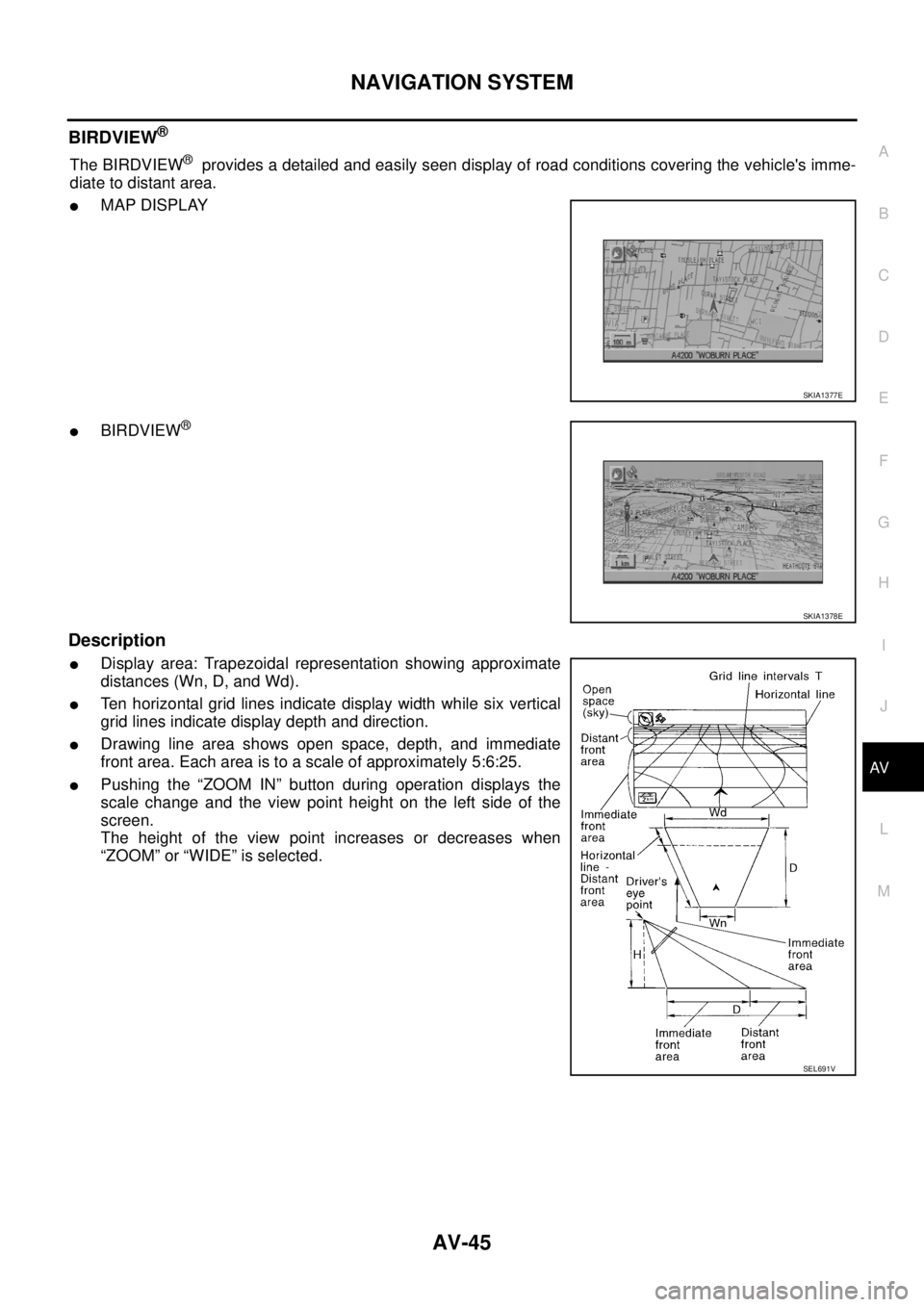
Description
�Display area: Trapezoidal representation showing approximate
distances (Wn, D, and Wd).
�Ten horizontal grid lines indicate display width while six vertical
grid lines indicate display depth and direction.
�Drawing line area shows open space, depth, and immediate
front area. Each area is to a scale of approximately 5:6:25.
�Pushing the “ZOOM IN” button during operation displays the
scale change and the view point height on the left side of the
screen.
The height of the view point increases or decreases when
“ZOOM” or “WIDE” is selected.
SKIA1377E
SKIA1378E
SEL691V
Page 4094 of 4179

ADJUSTING
1. Set the distance between the screen and the center of the driving lamp lens as shown in the figure.
2. Turn")
LT-16
HEADLAMP
ADJUSTMENT USING AN ADJUSTMENT SCREEN (LIGHT/DARK BORDERLINE)
ADJUSTING
1. Set the distance between the screen and the center of the driving lamp lens as shown in the figure.
2. Turn head lamp switch high and driving lamp switch ON so that front driving lamps turn ON.
3. Adjust driving lamps using adjusting screws make sure of the following.
�When performing this adjustment, cover the headlamps and the opposite driving lamp, if necessary.
�Vertical deflection of maximum illuminance point to be adjusted to stand at 21.8cm (8.58in) below driv-
ing lamp height (h).
�Horizontal deflection of maximum illuminance point to be adjusted to stand within 0 ± 12.5cm (0±8.58in)
against line (V) on screen where a line passing through driving lamp center, parallel to vehicle center
line, cross screen.
Bulb Replacement for Headlamp and Clearance lampEKS003CH
HEAD LAMP
1. Disconnect connector of headlamp.
2. Remove rubber cap.
3. Unlock retaining spring, then remove bulb.
CLEARANCE LAMP
1. Turn the RH and LH bulb sockets counterclockwise and unlock them.
2. Remove the bulb from its socket.
PKIA3395E
Headlamp (High/Low) : 12V 60/55 W(H4)
SKIA0073E
Page 4132 of 4179
LT-54
FRONT FOG LAMP
Aiming Adjustment EKS003DH
1. Set the distance between the screen and the center of the fog
lamp lens as shown at left.
2. Turn front fog lamps ON.
3. Insert a phillips screwdriver into the access hole and enage the
tip of the screwdriver with the gear of the adjuster as shown at
left. The aiming adjuster can now be turned by turning the
screwdriver.
4. Adjust front fog lamps so that the top edge of the high intensity
zone is 100 mm (4 in) below the height of the fog lamp centers
as shown at left.
�When performing adjustment, if necessary, cover the head-
lamps and opposite fog lamp.
PKIA8619E
PKIA5558E
MEL328G