Page 969 of 3066

TROUBLE DIAGNOSIS
BRC-101
[ESP/TCS/ABS]
C
D
E
G
H
I
J
K
L
MA
B
BRC
2.SELF-DIAGNOSIS RESULT CHECK 2
1. Disconnect connectors for the ESP/TCS/ABS control unit and the actuator. Securely connect them again.
2. Perform the self-diagnosis again.
Are any self-diagnosis items indicated again?
YES >> GO TO 3.
NO >> Repair or replace the poorly connected connector.
3.ACTUATOR MOTOR, MOTOR RELAY POWER SUPPLY CIRCUIT INSPECTION
1. Disconnect relay box connectors.
2. Check the voltage between the vehicle-side connector and body ground.
Is inspection result OK?
OK >> GO TO 4.
NG >>
lCheck the fuse 50A.
lCheck for continuity between the battery and the relay box terminal No. 10.
4.ACTUATOR MOTOR AND MOTOR RELAY CIRCUIT CHECK
1. Disconnect connectors for the ESP/TCS/ABS control unit and
the relay box.
2. Check for continuity between the ESP/TCS/ABS control unit,
the relay, and the actuator (vehicle-side connector).
Is inspection result OK?
YES >> GO TO 5.
NO >> Harness malfunction between the ESP/TCS/
ABS control unit, the relay box and the actuator.
SFIA0379E
Relay box
(Vehicle-side connector)Body ground Voltage value
10 – Battery voltage (approx. 12V)
ESP/TCS/ABS
control unit
(Vehicle-side
connector)Relay box
(Vehicle-side
connector)Actuator
(Vehicle-side
connector)Continuity
20 4 — Yes
78—Yes
— 41 [RHD] 21 [RHD] Yes
SFIA0380E
Page 971 of 3066

TROUBLE DIAGNOSIS
BRC-103
[ESP/TCS/ABS]
C
D
E
G
H
I
J
K
L
MA
B
BRC
4.ACTUATOR RELAY POWER SUPPLY CIRCUIT INSPECTION
1. Disconnect relay box connectors.
2. Check the voltage between the vehicle-side connector and body
ground.
Is inspection result OK?
YES >> GO TO 5.
NO >>
lCheck the fuse 30A.
lCheck for continuity between the battery and the relay box terminal No. 9. If it is not OK,
replace the fuse or harness.
5.ACTUATOR RELAY POWER CIRCUIT CHECK
1. Disconnect connectors for the ESP/TCS/ABS control unit and
the relay box.
2. Check for continuity between the ESP/TCS/ABS control unit
and the relay box (vehicle-side connector).
Is inspection result OK?
OK >> GO TO 6.
NG >> Harness disconnection between the ESP/TCS/ABS control unit and the relay box.
6.ACTUATOR RELAY UNIT INSPECTION
Check the actuator relay as a unit.
Is inspection result OK?
OK >> Check the ESP/TCS/ABS control unit power supply circuit.
NG >> Replace the actuator relay.
SFIA0382E
RELAY BOX
(Vehicle-side connector)Body ground Voltage value
9 – Battery voltage (approx. 12V)
SFIA0383E
ESP/TCS/ABS control unit
(Vehicle-side connector)Relay box
(Vehicle-side connector)Continuity
25Yes
36 7 Yes
Page 974 of 3066

BRC-106
[ESP/TCS/ABS]
TROUBLE DIAGNOSIS
5.ESP/TCS/ABS CONTROL UNIT POWER SUPPLY CIRCUIT INSPECTION 2
1. Check the fuse 10A.
2. Check for continuity between the battery positive terminal and
the ESP/TCS/ABS control unit connector.
Is inspection result OK?
YES >> Check the battery for a loose terminal and low voltage or the alternator for abnormality.
NO >>
lReplace the fuse 10A.
lHarness disconnection
Inspection 12 When “EMERGENCY BRAKE” is indicated in the Self-Diagnosis
Results
EFS001AO
Inspection procedure
1.SELF-DIAGNOSIS RESULT CHECK
Check the self-diagnosis results.
When any items other than²EMERGENCY BRAKE²is displayed in the self-diagnosis results, follow the
instructions below.
CAUTION:
²EMERGENCY BRAKE²is indicated when the control unit itself is detected internal error. If this display
item was indicated, replace the control unit.
Is
²EMERGENCY BRAKE²is indicated in the self-diagnosis results?
>> Replace the ESP/TCS/ABS control unit, and perform the self-diagnosis again.
Inspection 13 When “ST ANG SEN SIGNAL” is Indicated in the Self-Diagnosis
Results
EFS001AP
Inspection procedure
1.SELF-DIAGNOSIS RESULT CHECK 1
Check the self-diagnosis results.
When any items other than
²ST ANGLE SEN SIGNAL²is displayed in the self-diagnosis results:
YES >> Check and repair the applicable items. Perform the self-diagnosis again.
NO >> Perform the steering angle sensor neutral position adjustment. GO TO 2.
SFIA0387E
ESP/TCS/ABS control unit
(Vehicle-side connector)Battery terminal Continuity
1 positive Yes
Self-diagnosis results
CONSULT-II indication item
EMERGENCY BRAKE
Self-diagnosis results
CONSULT-II indication item
ST ANGLE SEN SIGNAL
Page 984 of 3066

BRC-116
[ESP/TCS/ABS]
TROUBLE DIAGNOSIS
Symptom 7: SLIP Indicator Lamp Does Not Illuminate
EFS001AY
Inspection procedure
1.SLIP INDICATOR LAMP BURNED-OUT BULB INSPECTION
Check for continuity between the power supply terminal of meter and terminal of ABS warning lamp.
Is inspection result OK?
OK >> GO TO 2.
NG >> Circuit malfunction in SLIP indicator lamp or combination meter
2.SLIP INDICATOR LAMP POWER CIRCUIT INSPECTION
Disconnect the meter connector. Check that the voltage between the vehicle-side harness terminal and body
ground is battery voltage (Approx. 12V).
Is inspection result OK?
YES >> GO TO 3.
NO >>
lFuse inspection
lInspection for harness and connectors between fuse block and meter
lCheck the power supply circuit (battery and ignition switch circuit).
3.SLIP INDICATOR LAMP HARNESS INSPECTION
1. Disconnect connectors for the ESP/TCS/ABS control unit and meter vehicle-side harness.
2. Check the harness between the meter and the ESP/TCS/ABS control unit for an open/shorted circuit.
Is inspection result OK?
OK >> GO TO 4.
NG >> Repair or replace the disconnected harness.
4.SLIP INDICATOR LAMP CONNECTOR INSPECTION
Check connectors for the ESP/TCS/ABS control unit and meter vehicle-side harness.
Is inspection result OK?
YES >> Connect connectors, and perform the self-diagnosis. The vehicle harness has the intermediate
connector. Refer to the vehicle wiring diagram, always check it.
NG >> Repair or replace the disconnected connector.
Symptom 8: During ESP/TCS/ABS Control, Vehicle Behavior is Jerky.EFS001AZ
Inspection procedure
1.ENGINE SPEED SIGNAL INSPECTION
Perform²DATA MONITOR²with CONSULT-II for the ESP/TCS/ABS control unit.
Is the engine speed at idle 400 rpm or higher?
YES >> Normal
NO >> GO TO 2.
2.SELF-DIAGNOSIS RESULT CHECK 1
Perform the ESP/TCS/ABS control unit self-diagnosis.
Is the self-diagnosis results displayed?
YES >> After checking and repairing the applicable item, perform the ESP/TCS/ABS control unit self-
diagnosis again.
NO >> GO TO 3.
Page 1058 of 3066
DI-4
COMBINATION METERS (LHD MODELS)
COMBINATION METERS (LHD MODELS)
PFP:24810
System DescriptionEKS002Z7
UNIFIED CONTROL METER
lSpeedometer, odo/trip meter, tachometer, fuel gauge and water temperature gauge are controlled totally
by control unit built-in combination meter.
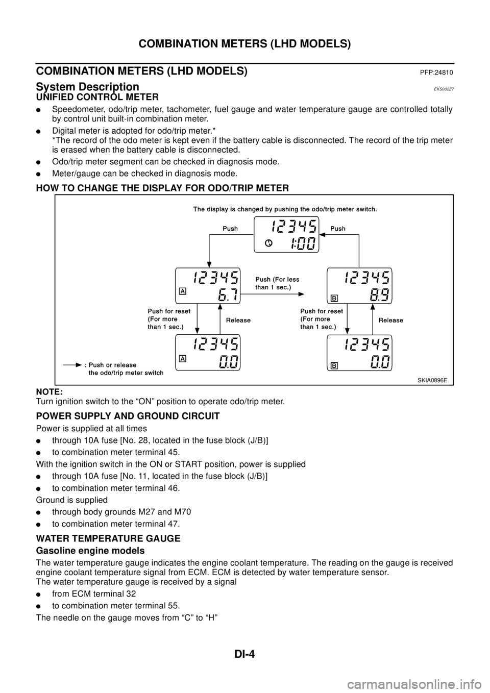
lDigital meter is adopted for odo/trip meter.*
*The record of the odo meter is kept even if the battery cable is disconnected. The record of the trip meter
is erased when the battery cable is disconnected.
lOdo/trip meter segment can be checked in diagnosis mode.
lMeter/gauge can be checked in diagnosis mode.
HOW TO CHANGE THE DISPLAY FOR ODO/TRIP METER
NOTE:
Turn ignition switch to the “ON” position to operate odo/trip meter.
POWER SUPPLY AND GROUND CIRCUIT
Power is supplied at all times
lthrough 10A fuse [No. 28, located in the fuse block (J/B)]
lto combination meter terminal 45.
With the ignition switch in the ON or START position, power is supplied
lthrough 10A fuse [No. 11, located in the fuse block (J/B)]
lto combination meter terminal 46.
Ground is supplied
lthrough body grounds M27 and M70
lto combination meter terminal 47.
WATER TEMPERATURE GAUGE
Gasoline engine models
The water temperature gauge indicates the engine coolant temperature. The reading on the gauge is received
engine coolant temperature signal from ECM. ECM is detected by water temperature sensor.
The water temperature gauge is received by a signal
lfrom ECM terminal 32
lto combination meter terminal 55.
The needle on the gauge moves from “C” to “H”
SKIA0896E
Page 1066 of 3066

DI-12
COMBINATION METERS (LHD MODELS)
Power Supply and Ground Circuit Check
EKS002ZE
1.POWER SUPPLY CIRCUIT CHECK
OK or NG?
OK >> GO TO 2.
NG >>
l10A fuse [No. 11, located in fuse block (J/B)].
l10A fuse [No. 28, located in fuse block (J/B)].
lHarness for open or short between fuse and combination meter.
2.GROUND CIRCUIT CHECK
OK or NG?
OK >> Inspection end.
NG >> Harness for open ground circuit.
Inspection/Engine Speed SignalEKS002ZF
1.CHECK ECM OUTPUT
1. Start engine.
2. Check voltage between combination meter harness connector
M46 terminals 54 (L/OR) and ground at idle and 2,000 rpm.
OK or NG?
OK >> Engine speed signal is OK.
NG >> Harness for open or short between ECM and combina-
tion meter.
Terminals Ignition switch position
(+)
(-)OFF ACC ON
ConnectorTe r m i n a l
(wire
color)
M46 45 (L) GroundBattery
voltageBattery
voltageBattery
voltage
M46 46 (W/L) Ground 0V 0VBattery
voltage
SKIA0982E
Te r m i n a l s
Continuity (+)
(-)
Connector Terminal
M46 47 Ground Yes
SKIA0983E
Higher rpm = Higher voltage
Lower rpm = Lower voltage
Voltage should change with rpm.
SKIA0984E
Page 1076 of 3066
DI-22
COMBINATION METERS (RHD MODELS)
COMBINATION METERS (RHD MODELS)
PFP:24810
System DescriptionEKS0030H
UNIFIED CONTROL METER
lSpeedometer, odo/trip meter, tachometer, fuel gauge and water temperature gauge are controlled totally
by control unit built-in combination meter.
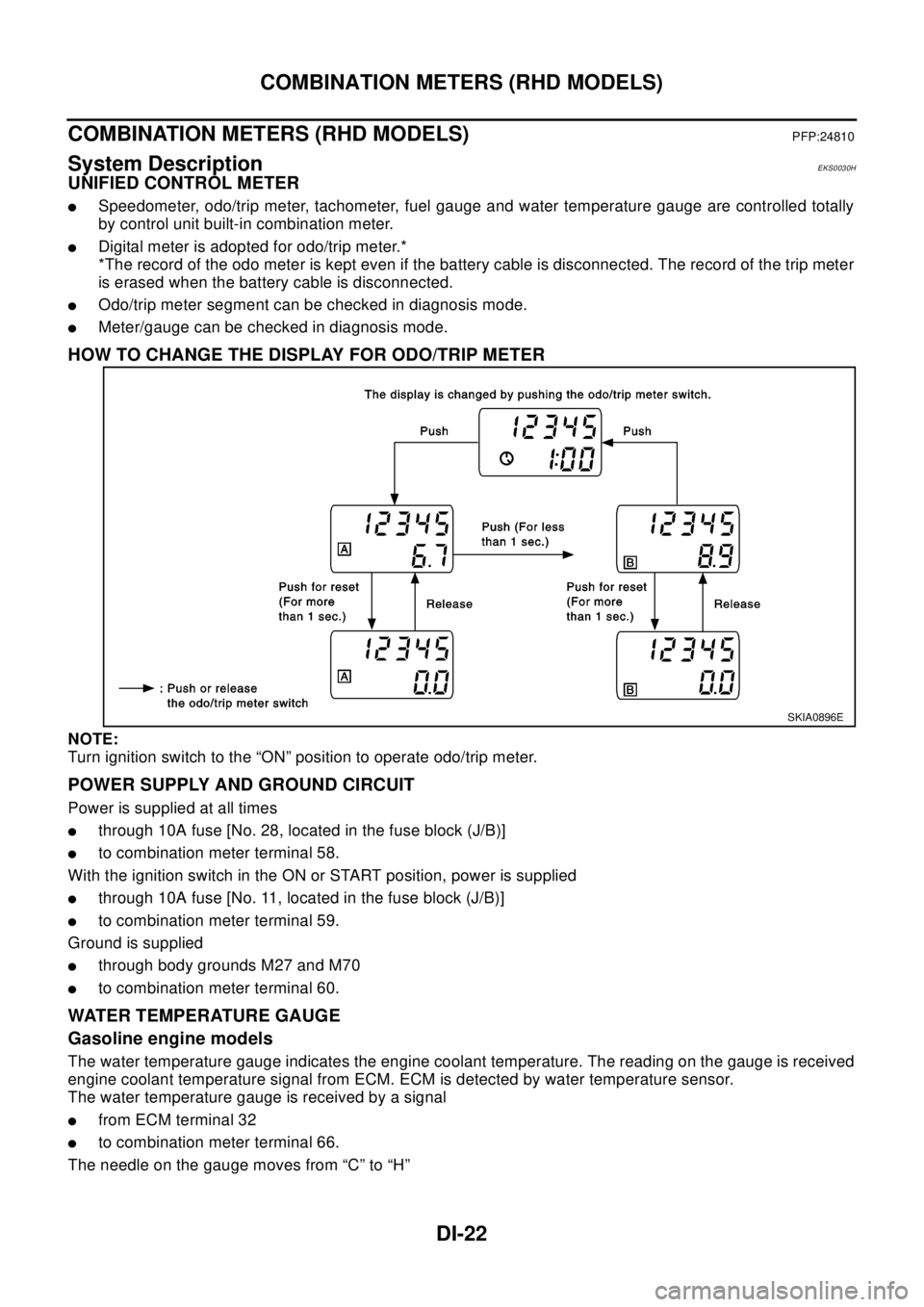
lDigital meter is adopted for odo/trip meter.*
*The record of the odo meter is kept even if the battery cable is disconnected. The record of the trip meter
is erased when the battery cable is disconnected.
lOdo/trip meter segment can be checked in diagnosis mode.
lMeter/gauge can be checked in diagnosis mode.
HOW TO CHANGE THE DISPLAY FOR ODO/TRIP METER
NOTE:
Turn ignition switch to the “ON” position to operate odo/trip meter.
POWER SUPPLY AND GROUND CIRCUIT
Power is supplied at all times
lthrough 10A fuse [No. 28, located in the fuse block (J/B)]
lto combination meter terminal 58.
With the ignition switch in the ON or START position, power is supplied
lthrough 10A fuse [No. 11, located in the fuse block (J/B)]
lto combination meter terminal 59.
Ground is supplied
lthrough body grounds M27 and M70
lto combination meter terminal 60.
WATER TEMPERATURE GAUGE
Gasoline engine models
The water temperature gauge indicates the engine coolant temperature. The reading on the gauge is received
engine coolant temperature signal from ECM. ECM is detected by water temperature sensor.
The water temperature gauge is received by a signal
lfrom ECM terminal 32
lto combination meter terminal 66.
The needle on the gauge moves from “C” to “H”
SKIA0896E
Page 1084 of 3066

DI-30
COMBINATION METERS (RHD MODELS)
Power Supply and Ground Circuit Check
EKS0030O
1.POWER SUPPLY CIRCUIT CHECK
OK or NG ?
OK >> GO TO 2.
NG >>
l10A fuse [No. 11, located in fuse block (J/B)].
l10A fuse [No. 28, located in fuse block (J/B)].
lHarness for open or short between fuse and combination meter.
2.GROUND CIRCUIT CHECK
OK or NG ?
OK >> Inspection end.
NG >> Harness for open ground circuit.
Inspection/Engine Speed SignalEKS0030P
1.CHECK ECM OUTPUT
1. Start engine.
2. Check voltage between combination meter harness connector
M46 terminals 41 (L/OR) and ground at idle and 2,000 rpm.
OK or NG ?
OK >> Engine speed signal is OK.
NG >> Harness for open or short between ECM and combina-
tion meter.
Terminals Ignition switch position
(+)
(-)OFF ACC ON
ConnectorTe r m i n a l
(wire
color)
M46 58(L) GroundBattery
voltageBattery
voltageBattery
voltage
M46 59(W/L) Ground 0V 0VBattery
voltage
SKIA1019E
Te r m i n a l s
Continuity (+)
(-)
Connector Terminal
M46 60 Ground Yes
SKIA1020E
Higher rpm = Higher voltage
Lower rpm = Lower voltage
Voltage should change with rpm.
SKIA1021E