2003 NISSAN X-TRAIL fuse
[x] Cancel search: fusePage 435 of 3066
![NISSAN X-TRAIL 2003 Electronic Repair Manual BATT/FLUID TEMP SEN (A/T FLUID TEMP SENSOR CIRCUIT AND TCM POW-
ER SOURCE)
AT-429
[ALL]
D
E
F
G
H
I
J
K
L
MA
B
AT
Diagnostic ProcedureECS004UA
1.CHECK TCM POWER SOURCE
1. Turn ignition switch to “ON NISSAN X-TRAIL 2003 Electronic Repair Manual BATT/FLUID TEMP SEN (A/T FLUID TEMP SENSOR CIRCUIT AND TCM POW-
ER SOURCE)
AT-429
[ALL]
D
E
F
G
H
I
J
K
L
MA
B
AT
Diagnostic ProcedureECS004UA
1.CHECK TCM POWER SOURCE
1. Turn ignition switch to “ON](/manual-img/5/57402/w960_57402-434.png)
BATT/FLUID TEMP SEN (A/T FLUID TEMP SENSOR CIRCUIT AND TCM POW-
ER SOURCE)
AT-429
[ALL]
D
E
F
G
H
I
J
K
L
MA
B
AT
Diagnostic ProcedureECS004UA
1.CHECK TCM POWER SOURCE
1. Turn ignition switch to “ON” position.
(Do not start engine.)
2. Check voltage between TCM terminals 10, 19, 28 and ground.
3. Turn ignition switch to “OFF” position.
4. Check voltage between TCM terminal 28 and ground.
OK or NG
OK >> GO TO 2
NG >> Check the following items:
lHarness for short or open between ignition switch and
TCM (Main harness)
lIgnition switch and fuse
Refer to “PG-2, "
POWER SUPPLY ROUTING"”,
“POWER SUPPLY ROUTING”.
2.CHECK A/T FLUID TEMPERATURE SENSOR WITH TERMINAL CORD ASSEMBLY
1. Turn ignition switch to “OFF” position.
2. Disconnect terminal cord assembly connector in engine compartment.
3. Check resistance between terminals 6 and 7 when A/T is cold.
4. Reinstall any part removed.
OK or NG
OK (With CONSULT-II)>>GO TO 3
OK (Without CONSULT-II)>>GO TO 4
NG >> 1. Remove oil pan.
2. Check the following items:
A/T fluid temperature sensor
Refer to “Component Inspection”,AT-431, "
Compo-
nent Inspection".
Harness of terminal cord assembly for short or open Voltage:Batteryvoltage
Voltage:Batteryvoltage
SCIA0736E
Resistance Cold[20°C(68°F)]
: Approximately 2.5 kW
SCIA0737E
Page 454 of 3066
![NISSAN X-TRAIL 2003 Electronic Repair Manual AT-448
[ALL]
A/T SHIFT LOCK SYSTEM
Diagnostic Procedure
ECS00408
SYMPTOM 1:
lSelector lever cannot be moved from “P” position with key in ON position and brake pedal
applied.
lSelector lever can b NISSAN X-TRAIL 2003 Electronic Repair Manual AT-448
[ALL]
A/T SHIFT LOCK SYSTEM
Diagnostic Procedure
ECS00408
SYMPTOM 1:
lSelector lever cannot be moved from “P” position with key in ON position and brake pedal
applied.
lSelector lever can b](/manual-img/5/57402/w960_57402-453.png)
AT-448
[ALL]
A/T SHIFT LOCK SYSTEM
Diagnostic Procedure
ECS00408
SYMPTOM 1:
lSelector lever cannot be moved from “P” position with key in ON position and brake pedal
applied.
lSelector lever can be moved from “P” position with key in ON position and brake pedal released.
lSelector lever can be moved from “P” position when key is removed from key cylinder.
SYMPTOM 2:
Ignition key cannot be removed when selector lever is set to “P” position. It can be removed when
selector lever is set to any position except “P”.
1.CHECKKEYINTERLOCKCABLE
Check key interlock cable for damage.
OK or NG
OK >> GO TO 2
NG >> Repair key interlock cable. Refer toAT - 4 5 2 , "
KEY INTERLOCK CABLE".
2.CHECK SELECTOR LEVER POSITION
Check selector lever position for damage.
OK or NG
OK >> GO TO 3
NG >> Check selector lever. Refer toAT - 4 5 6 , "
Park/Neutral Position (PNP) Switch Adjustment".
3.CHECK POWER SOURCE
1. Turn ignition switch to “ON” position.
(Do not start engine.)
2. Check voltage between stop lamp switch harness terminal 1 and ground.
OK or NG
OK >> GO TO 4
NG >> Check the following items:
1. Harness for short or open between battery and stop
lamp switch harness terminal 1
2. Fuse
3. Ignition switch (Refer toPG-2, "
POWER SUPPLY
ROUTING".) Voltage : Battery voltageSCIA0782E
Page 455 of 3066
![NISSAN X-TRAIL 2003 Electronic Repair Manual A/T SHIFT LOCK SYSTEM
AT-449
[ALL]
D
E
F
G
H
I
J
K
L
MA
B
AT
4.CHECK INPUT SIGNAL (A/T DEVICE)
Turn ignition switch to “ON” position.
(Do not start engine.)
lCheck voltage between A/T device harne NISSAN X-TRAIL 2003 Electronic Repair Manual A/T SHIFT LOCK SYSTEM
AT-449
[ALL]
D
E
F
G
H
I
J
K
L
MA
B
AT
4.CHECK INPUT SIGNAL (A/T DEVICE)
Turn ignition switch to “ON” position.
(Do not start engine.)
lCheck voltage between A/T device harne](/manual-img/5/57402/w960_57402-454.png)
A/T SHIFT LOCK SYSTEM
AT-449
[ALL]
D
E
F
G
H
I
J
K
L
MA
B
AT
4.CHECK INPUT SIGNAL (A/T DEVICE)
Turn ignition switch to “ON” position.
(Do not start engine.)
lCheck voltage between A/T device harness terminal 7 and ground.
OK or NG
OK >> GO TO 5
NG >> Check the following items:
1. Harness for short and open between battery and stop
lamp switch harness connector 1.
2. Harness for short or open between stop lamp switch harness connector 2 and A/T device har-
ness connector 7.
3. Fuse
4. Stop lamp switch (Refer toAT- 4 5 0 , "
A/T DEVICE CHECK".)
5.CHECK GROUND CIRCUIT
1. Turn ignition switch to “OFF” position.
2. Disconnect A/T device harness connector.
3. Check continuity between A/T device harness terminal 6 and ground.
If OK, check harness for short to ground and short to power.
OK or NG
OK >> GO TO 6
NG >> Repair open circuit or short to ground or short to power
in harness or connectors. Voltage:
Brake pedal depressd:
Battery voltage
Brake pedal released:
0V
SCIA0783E
Continuity should exist.
SCIA0784E
Page 584 of 3066

ATC-6
PRECAUTIONS
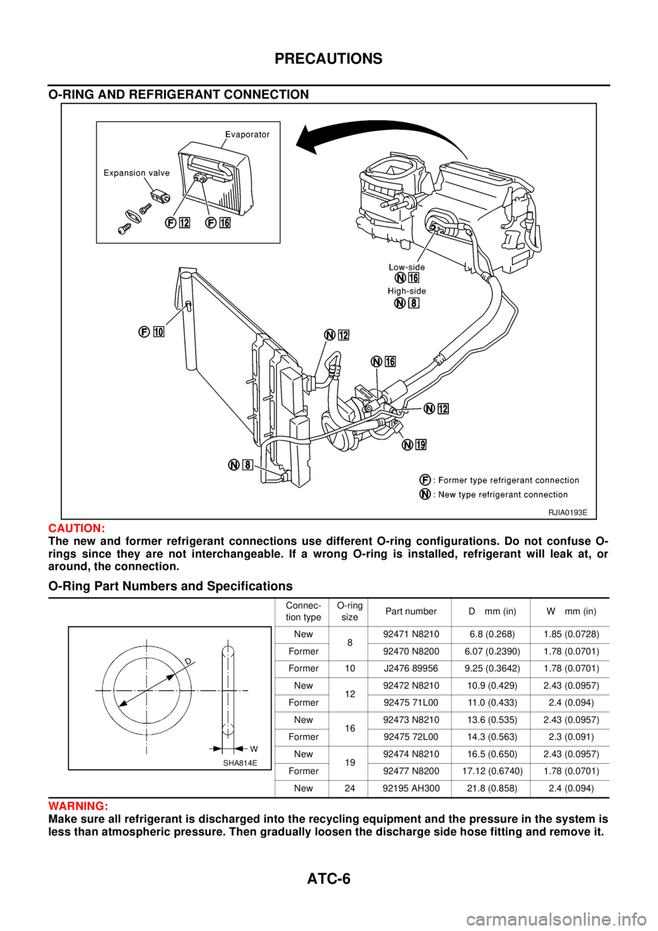
O-RING AND REFRIGERANT CONNECTION
CAUTION:
The new and former refrigerant connections use different O-ring configurations. Do not confuse O-
rings since they are not interchangeable. If a wrong O-ring is installed, refrigerant will leak at, or
around, the connection.
O-Ring Part Numbers and Specifications
WAR NIN G:
Make sure all refrigerant is discharged into the recycling equipment and the pressure in the system is
less than atmospheric pressure. Then gradually loosen the discharge side hose fitting and remove it.
RJIA0193E
Connec-
tion typeO-ring
sizePart number D mm (in) W mm (in)
New
892471 N8210 6.8 (0.268) 1.85 (0.0728)
Former 92470 N8200 6.07 (0.2390) 1.78 (0.0701)
Former 10 J2476 89956 9.25 (0.3642) 1.78 (0.0701)
New
1292472 N8210 10.9 (0.429) 2.43 (0.0957)
Former 92475 71L00 11.0 (0.433) 2.4 (0.094)
New
1692473 N8210 13.6 (0.535) 2.43 (0.0957)
Former 92475 72L00 14.3 (0.563) 2.3 (0.091)
New
1992474 N8210 16.5 (0.650) 2.43 (0.0957)
Former 92477 N8200 17.12 (0.6740) 1.78 (0.0701)
New 24 92195 AH300 21.8 (0.858) 2.4 (0.094)
SHA814E
Page 633 of 3066

TROUBLE DIAGNOSIS
ATC-55
C
D
E
F
G
H
I
K
L
MA
B
AT C
DIAGNOSTIC PROCEDURE
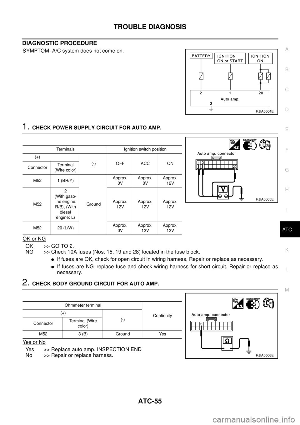
SYMPTOM: A/C system does not come on.
1.CHECK POWER SUPPLY CIRCUIT FOR AUTO AMP.
OK or NG
OK >> GO TO 2.
NG >> Check 10A fuses (Nos. 15, 19 and 28) located in the fuse block.
lIf fuses are OK, check for open circuit in wiring harness. Repair or replace as necessary.
lIf fuses are NG, replace fuse and check wiring harness for short circuit. Repair or replace as
necessary.
2.CHECK BODY GROUND CIRCUIT FOR AUTO AMP.
Ye s o r N o
Yes >> Replace auto amp. INSPECTION END
No >> Repair or replace harness.
RJIA0504E
Terminals Ignition switch position
(+)
(-) OFF ACC ON
ConnectorTe r m i n a l
(Wire color)
M52 1 (BR/Y)
GroundApprox.
0VApprox.
0VApprox.
12V
M522
(With gaso-
line engine:
R/B), (With
diesel
engine: L)Approx.
12VApprox.
12VApprox.
12V
M52 20 (L/W)Approx.
0VApprox.
12VApprox.
12V
RJIA0505E
Ohmmeter terminal
Continuity (+)
(-)
ConnectorTerminal (Wire
color)
M52 3 (B) Ground Yes
RJIA0506E
Page 649 of 3066

TROUBLE DIAGNOSIS
ATC-71
C
D
E
F
G
H
I
K
L
MA
B
AT C
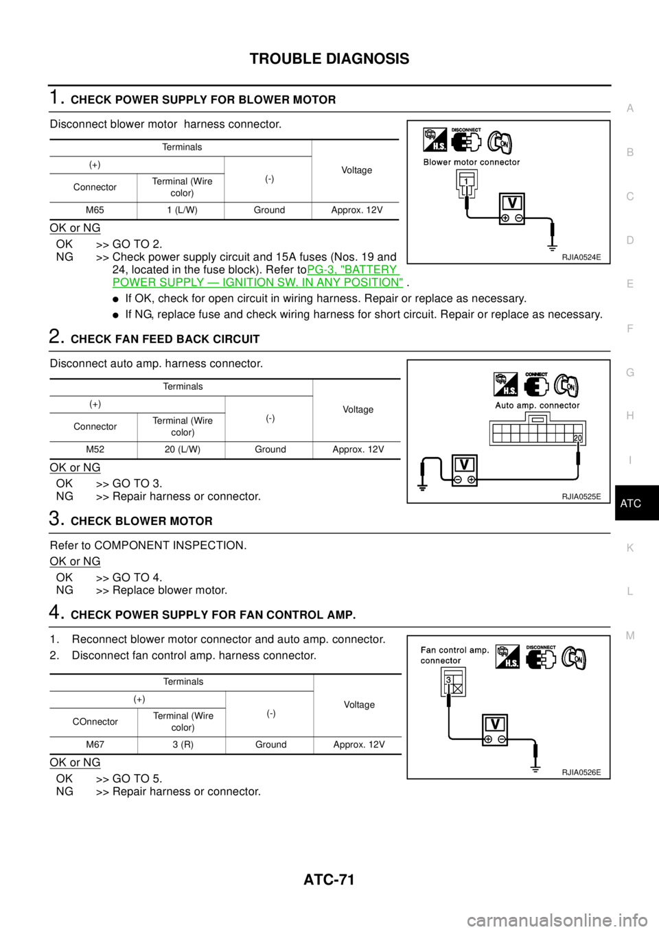
1.CHECK POWER SUPPLY FOR BLOWER MOTOR
Disconnect blower motor harness connector.
OK or NG
OK >> GO TO 2.
NG >> Check power supply circuit and 15A fuses (Nos. 19 and
24, located in the fuse block). Refer toPG-3, "
BATTERY
POWER SUPPLY—IGNITION SW. IN ANY POSITION".
lIf OK, check for open circuit in wiring harness. Repair or replace as necessary.
lIf NG, replace fuse and check wiring harness for short circuit. Repair or replace as necessary.
2.CHECK FAN FEED BACK CIRCUIT
Disconnect auto amp. harness connector.
OK or NG
OK >> GO TO 3.
NG >> Repair harness or connector.
3.CHECKBLOWERMOTOR
Refer to COMPONENT INSPECTION.
OK or NG
OK >> GO TO 4.
NG >> Replace blower motor.
4.CHECK POWER SUPPLY FOR FAN CONTROL AMP.
1. Reconnect blower motor connector and auto amp. connector.
2. Disconnect fan control amp. harness connector.
OK or NG
OK >> GO TO 5.
NG >> Repair harness or connector.
Te r m i n a l s
Vo l ta g e (+)
(-)
ConnectorTerminal (Wire
color)
M65 1 (L/W) Ground Approx. 12V
RJIA0524E
Te r m i n a l s
Vo l ta g e (+)
(-)
ConnectorTerminal (Wire
color)
M52 20 (L/W) Ground Approx. 12V
RJIA0525E
Terminals
Voltage (+)
(-)
COnnectorTerminal (Wire
color)
M67 3 (R) Ground Approx. 12V
RJIA0526E
Page 654 of 3066

ATC-76
TROUBLE DIAGNOSIS
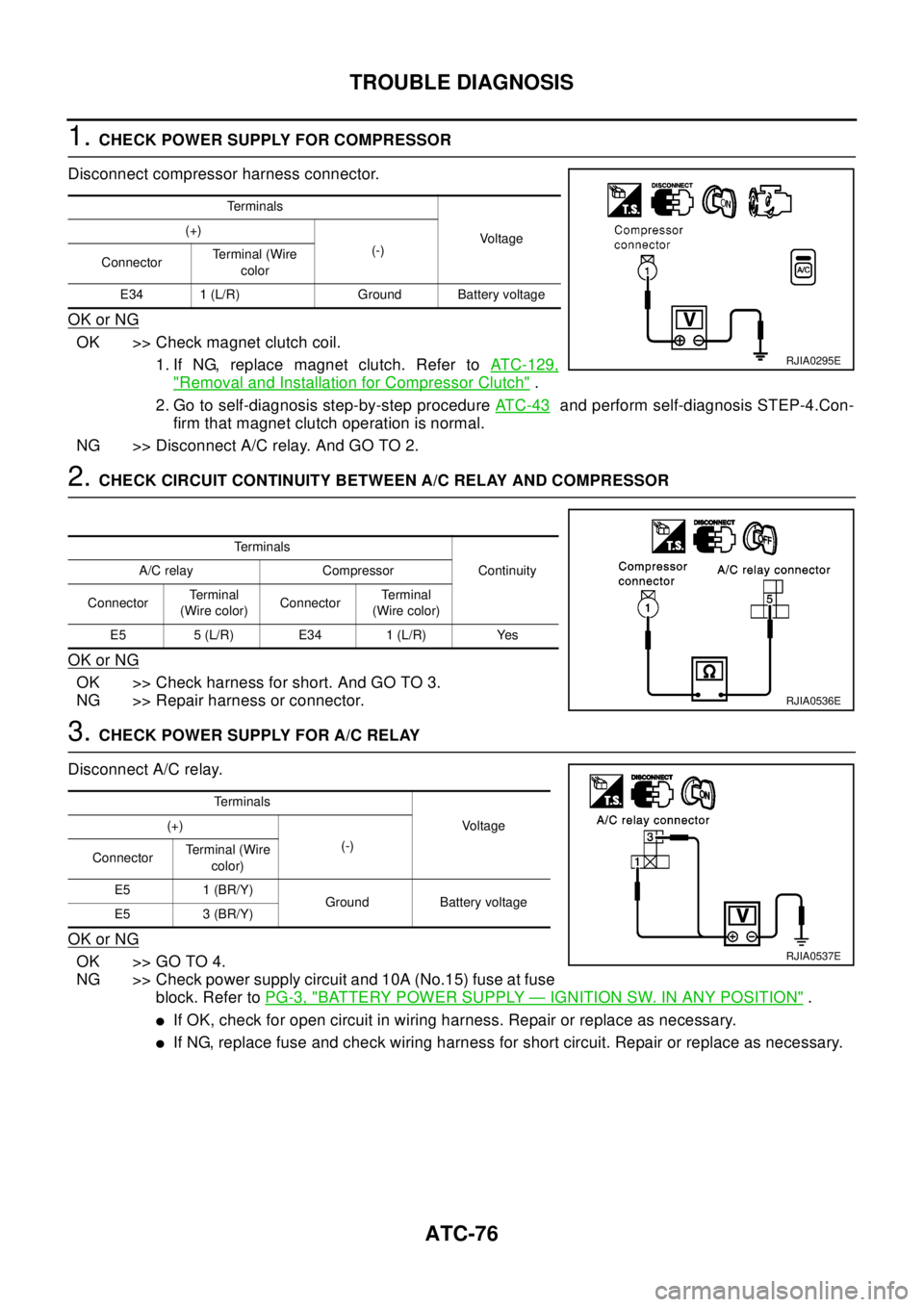
1.CHECK POWER SUPPLY FOR COMPRESSOR
Disconnect compressor harness connector.
OK or NG
OK >> Check magnet clutch coil.
1. If NG, replace magnet clutch. Refer toATC-129,
"Removal and Installation for Compressor Clutch".
2. Go to self-diagnosis step-by-step procedureAT C - 4 3
and perform self-diagnosis STEP-4.Con-
firm that magnet clutch operation is normal.
NG >>DisconnectA/Crelay.AndGOTO2.
2.CHECK CIRCUIT CONTINUITY BETWEEN A/C RELAY AND COMPRESSOR
OK or NG
OK >> Check harness for short. And GO TO 3.
NG >> Repair harness or connector.
3.CHECK POWER SUPPLY FOR A/C RELAY
Disconnect A/C relay.
OK or NG
OK >> GO TO 4.
NG >> Check power supply circuit and 10A (No.15) fuse at fuse
block. Refer toPG-3, "
BATTERY POWER SUPPLY—IGNITION SW. IN ANY POSITION".
lIf OK, check for open circuit in wiring harness. Repair or replace as necessary.
lIf NG, replace fuse and check wiring harness for short circuit. Repair or replace as necessary.
Te r m i n a l s
Vo l ta g e (+)
(-)
ConnectorTerminal (Wire
color
E34 1 (L/R) Ground Battery voltage
RJIA0295E
Te r m i n a l s
Continuity A/C relay Compressor
ConnectorTe r m i n a l
(Wire color)ConnectorTe r m i n a l
(Wire color)
E5 5 (L/R) E34 1 (L/R) Yes
RJIA0536E
Te r m i n a l s
Vo l ta g e (+)
(-)
ConnectorTerminal (Wire
color)
E5 1 (BR/Y)
Ground Battery voltage
E5 3 (BR/Y)
RJIA0537E
Page 725 of 3066

AUDIO
AV-3
C
D
E
F
G
H
I
J
L
MA
B
AV
AUDIOP F P : 2 8 111
System DescriptionEKS002F2
Refer to Owner's Manual for audio system operating instructions.
Power is supplied at all times
lthrough 15A fuse (No. 32, located in the fusible link and fuse block)
lto audio unit terminal 3
lto CD auto changer terminal 32.
With the ignition switch in the ACC or ON position, power is supplied
lthrough 10A fuse [No. 4, located in the fuse block (J/B)]
lto audio unit terminal 6,
lto CD auto changer terminal 36
Ground is supplied through the case of the audio unit.
Audio signals are supplied
lthrough audio unit terminals 5, 7, 9, 10, 11, 13, 15, 16
lto terminals 1 and 2 of front door speaker LH and RH,
lto terminals 1 and 2 of rear door speaker LH and RH and
lto terminals 1 and 2 of tweeter LH and RH (with 6 speakers)
NATS AUDIO LINK
Description
The link with the NATS IMMU implies that the audio unit can basically only be operated if connected to the
matching NATS IMMU to which the audio unit was initially fitted on the production line.
Since radio operation is impossible after the link with the NATS is disrupted theft of the audio unit is basically
useless since special equipment is required to reset the audio unit.
Initialization process for audio units that are linked to the NATS IMMU
New audio units will be delivered to the factories in the “NEW” state, i.e. ready to be linked with the vehicle's
NATS. When the audio unit in “NEW” state is first switched on at the factory, it will start up communication with
the vehicle's immobilizer control unit (IMMU) and send a code (the “audio unit Code”) to the IMMU. The IMMU
will then store this code, which is unique to each audio unit, in its (permanent) memory.
Upon receipt of the code by the IMMU, the NATS will confirm correct receipt of the audio unit code to the audio
unit. Hereafter, the audio unit will operate as normal.
During the initialization process, “NEW” is displayed on the audio unit display. Normally though, communica-
tion between audio unit and IMMU takes such a short time (300 ms) that the audio unit seems to switch on
directly without showing “NEW” on its display.
Normal operation
Each time the audio unit is switched on afterwards, the audio unit code will be verified between the audio unit
and the NATS before the audio unit becomes operational. During the code verification process, “WAIT” is
shown on the audio unit display. Again, the communication takes such a short time (300 ms) that the audio
unit seems to switch on directly without showing “WAIT” on its display.
When the radio is locked
In case of a audio unit being linked with the vehicle's NATS (immobilizer system), disconnection of the link
between the audio unit and the IMMU will cause the audio unit to switch into the lock (“SECURE”) mode in
which the audio unit is fully inoperative. Hence, repair of the audio unit is basically impossible, unless the
audio unit is reset to the “NEW” state for which special decoding equipment is required.
Clarion has provided their authorized service representatives with so called “decoder boxes” which can bring
the audio unit back to the “NEW” state, enabling the audio unit to be switched on after which repair can be car-
ried out. Subsequently, when the repaired audio unit is delivered to the final user again, it will be in the “NEW”
state to enable re-linking the audio unit to the vehicle's immobilizer system. As a result of the above, repair of
the audio unit can only be done by an authorized Clarion representative (when the owner of the vehicle
requests repair and can show personal identification).