2003 NISSAN X-TRAIL fuse
[x] Cancel search: fusePage 2947 of 3066
TROUBLE DIAGNOSIS
SRS-25
C
D
E
F
G
I
J
K
L
MA
B
SRS
Trouble Diagnoses: “AIR BAG” Warning Lamp Does Not Turn OffEHS000CU
DIAGNOSTIC PROCEDURE 6
1.SEE THE DEPLOYMENT OF AIR BAG MODULE
Is air bag module deployed?
Ye s o r N o
Yes >> Refer toSRS-46, "COLLISION DIAGNOSIS".
No >> GO TO 2.
2.CHECK THE AIR BAG FUSE
Check the fuse (No.20).
Refer toPG-2, "
POWER SUPPLY ROUTING".
OK or NG
OK >> GO TO 4.
NG >> GO TO 3.
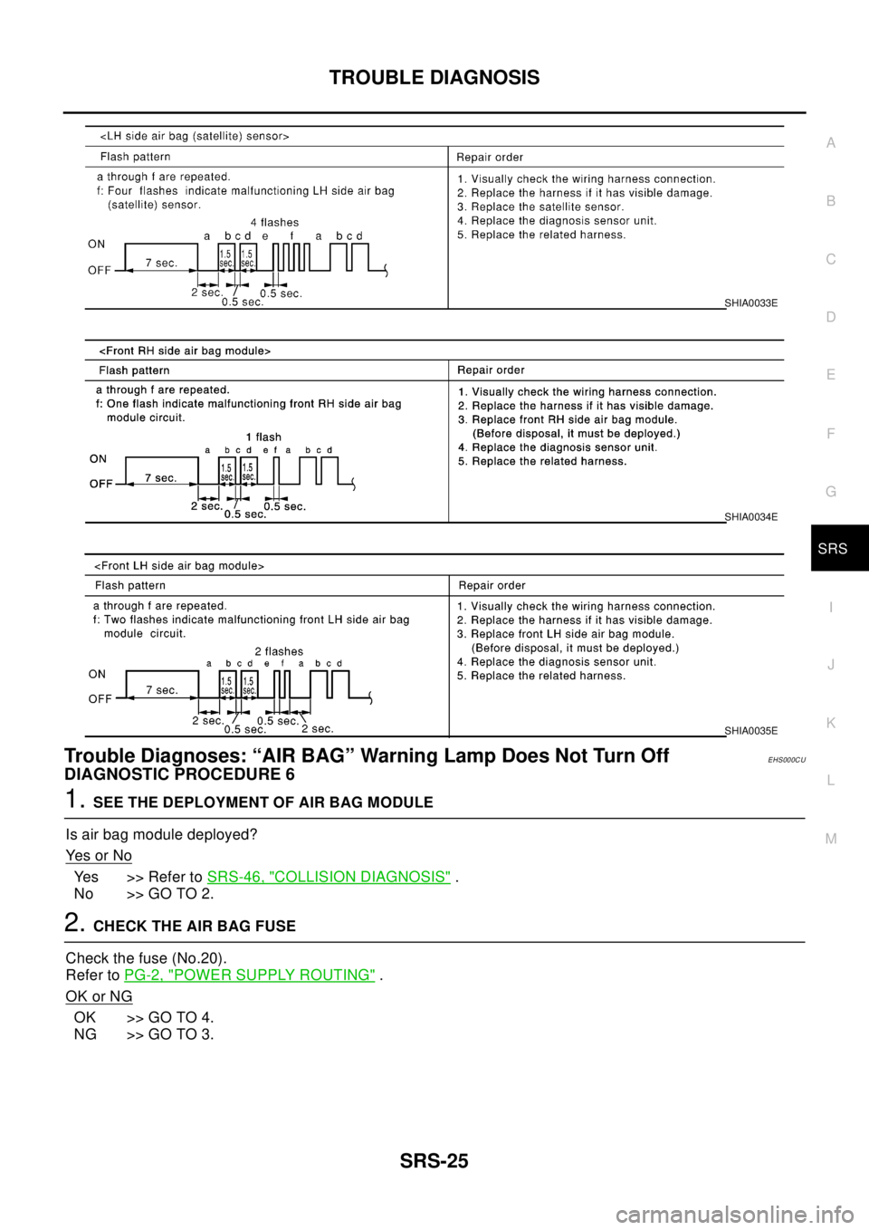
SHIA0033E
SHIA0034E
SHIA0035E
Page 2948 of 3066
SRS-26
TROUBLE DIAGNOSIS
3.CHECK AIR BAG FUSE AGAIN
Replace “AIR BAG” fuse and turn ignition switch ON.
Is
“AIR BAG”fuse blown again?
Yes >> Repair main harness.
No >>INSPECTION END
4.CHECK DIAGNOSIS SENSOR UNIT
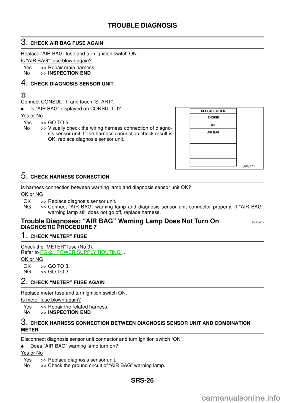
Connect CONSULT-II and touch “START”.
lIs “AIR BAG” displayed on CONSULT-II?
Ye s o r N o
Yes >>GOTO5.
No >> Visually check the wiring harness connection of diagno-
sis sensor unit. If the harness connection check result is
OK, replace diagnosis sensor unit.
5.CHECK HARNESS CONNECTION
Is harness connection between warning lamp and diagnosis sensor unit OK?
OK or NG
OK >> Replace diagnosis sensor unit.
NG >> Connect “AIR BAG” warning lamp and diagnosis sensor unit connector properly. If “AIR BAG”
warning lamp still does not go off, replace harness.
Trouble Diagnoses: “AIR BAG” Warning Lamp Does Not Turn OnEHS000CV
DIAGNOSTIC PROCEDURE 7
1.CHECK “METER” FUSE
Check the “METER” fuse (No.9).
Refer toPG-2, "
POWER SUPPLY ROUTING".
OK or NG
OK >> GO TO 3.
NG >> GO TO 2.
2.CHECK “METER” FUSE AGAIN
Replace meter fuse and turn ignition switch ON.
Is meter fuse blown again?
Yes >> Repair the related harness.
No >>INSPECTION END
3.CHECK HARNESS CONNECTION BETWEEN DIAGNOSIS SENSOR UNIT AND COMBINATION
METER
Disconnect diagnosis sensor unit connector and turn ignition switch “ON”.
lDoes “AIR BAG” warning lamp turn on?
Ye s o r N o
Yes >> Replace diagnosis sensor unit.
No >> Check the ground circuit of “AIR BAG” warning lamp.
SRS771
Page 3011 of 3066
TROUBLE DIAGNOSIS
TF-41
C
E
F
G
H
I
J
K
L
MA
B
TF
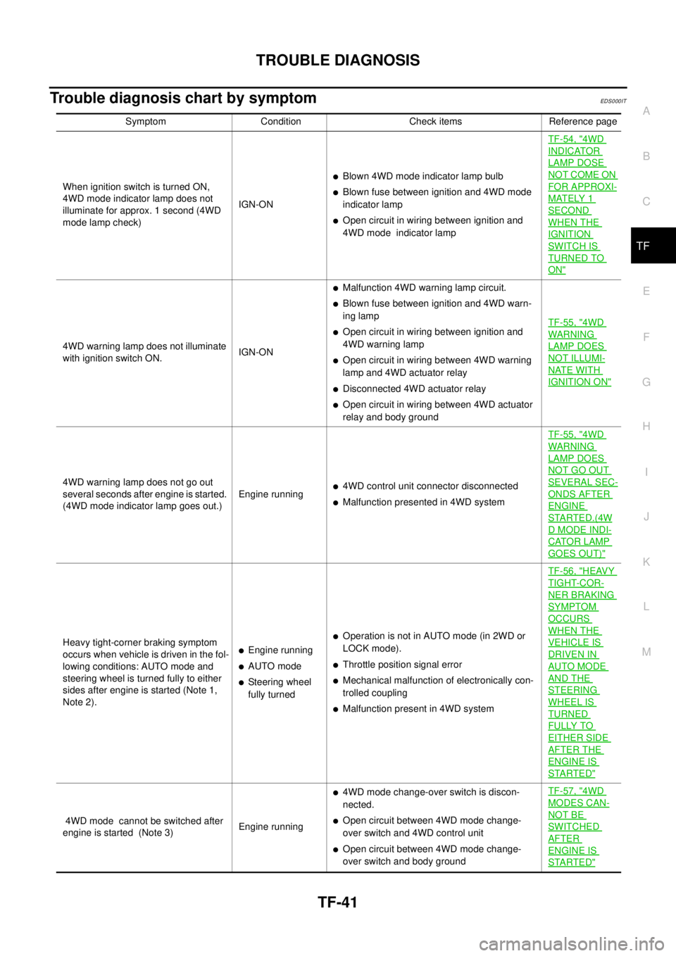
Trouble diagnosis chart by symptomEDS0 00 IT
Symptom Condition Check items Reference page
When ignition switch is turned ON,
4WD mode indicator lamp does not
illuminate for approx. 1 second (4WD
mode lamp check)IGN-ON
lBlown 4WD mode indicator lamp bulb
lBlown fuse between ignition and 4WD mode
indicator lamp
lOpen circuit in wiring between ignition and
4WD mode indicator lampTF-54, "
4WD
INDICATOR
LAMP DOSE
NOT COME ON
FOR APPROXI-
MATELY 1
SECOND
WHEN THE
IGNITION
SWITCH IS
TURNED TO
ON"
4WD warning lamp does not illuminate
with ignition switch ON.IGN-ON
lMalfunction 4WD warning lamp circuit.
lBlown fuse between ignition and 4WD warn-
ing lamp
lOpen circuit in wiring between ignition and
4WD warning lamp
lOpen circuit in wiring between 4WD warning
lamp and 4WD actuator relay
lDisconnected 4WD actuator relay
lOpen circuit in wiring between 4WD actuator
relay and body groundTF-55, "
4WD
WAR NIN G
LAMP DOES
NOT ILLUMI-
NATE WITH
IGNITION ON"
4WD warning lamp does not go out
several seconds after engine is started.
(4WD mode indicator lamp goes out.)Engine runningl4WD control unit connector disconnected
lMalfunction presented in 4WD systemTF-55, "
4WD
WAR NIN G
LAMP DOES
NOT GO OUT
SEVERAL SEC-
ONDS AFTER
ENGINE
STARTED.(4W
DMODEINDI-
CATOR LAMP
GOES OUT)"
Heavy tight-corner braking symptom
occurs when vehicle is driven in the fol-
lowing conditions: AUTO mode and
steering wheel is turned fully to either
sides after engine is started (Note 1,
Note 2).lEngine running
lAUTO mode
lSteering wheel
fully turned
lOperation is not in AUTO mode (in 2WD or
LOCK mode).
lThrottle position signal error
lMechanical malfunction of electronically con-
trolled coupling
lMalfunction present in 4WD systemTF-56, "
HEAVY
TIGHT-COR-
NER BRAKING
SYMPTOM
OCCURS
WHEN THE
VEHICLE IS
DRIVEN IN
AUTO MODE
AND THE
STEERING
WHEEL IS
TURNED
FULLY TO
EITHER SIDE
AFTER THE
ENGINE IS
STARTED"
4WD mode cannot be switched after
engine is started (Note 3)Engine running
l4WD mode change-over switch is discon-
nected.
lOpen circuit between 4WD mode change-
over switch and 4WD control unit
lOpen circuit between 4WD mode change-
over switch and body groundTF-57, "
4WD
MODES CAN-
NOT BE
SWITCHED
AFTER
ENGINE IS
STARTED"
Page 3022 of 3066
TF-52
TROUBLE DIAGNOSIS
4.INSPECTION OF 4WD SOLENOID CIRCUIT HARNESS
1. Disconnect the 4WD solenoid connector.
2. Disconnect the 4WD control unit.
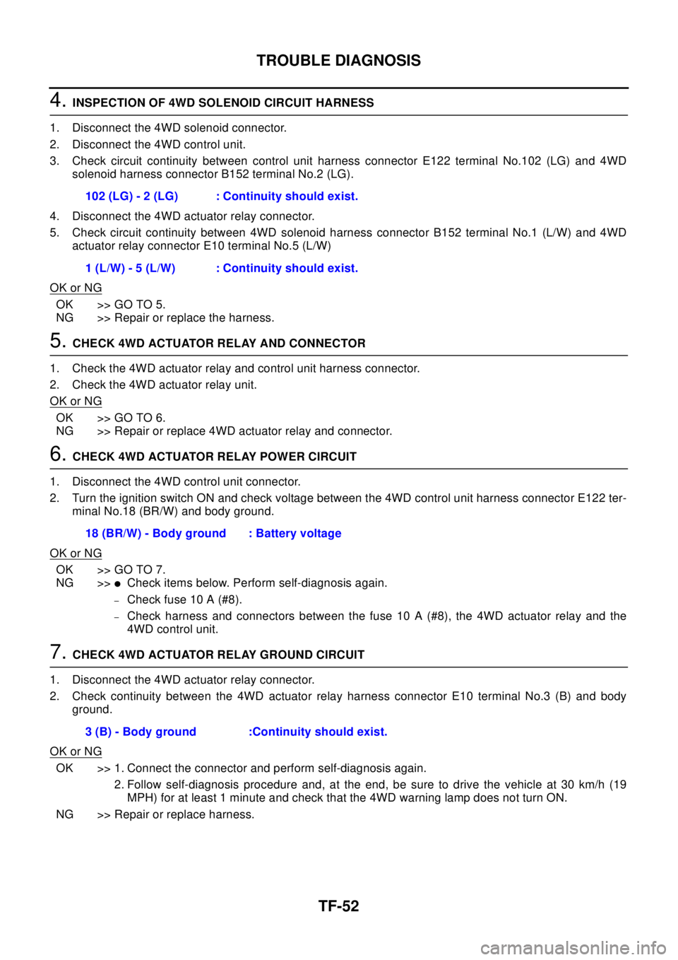
3. Check circuit continuity between control unit harness connector E122 terminal No.102 (LG) and 4WD
solenoid harness connector B152 terminal No.2 (LG).
4. Disconnect the 4WD actuator relay connector.
5. Check circuit continuity between 4WD solenoid harness connector B152 terminal No.1 (L/W) and 4WD
actuator relay connector E10 terminal No.5 (L/W)
OK or NG
OK >> GO TO 5.
NG >> Repair or replace the harness.
5.CHECK 4WD ACTUATOR RELAY AND CONNECTOR
1. Check the 4WD actuator relay and control unit harness connector.
2. Check the 4WD actuator relay unit.
OK or NG
OK >> GO TO 6.
NG >> Repair or replace 4WD actuator relay and connector.
6.CHECK 4WD ACTUATOR RELAY POWER CIRCUIT
1. Disconnect the 4WD control unit connector.
2. Turn the ignition switch ON and check voltage between the 4WD control unit harness connector E122 ter-
minal No.18 (BR/W) and body ground.
OK or NG
OK >> GO TO 7.
NG >>
lCheck items below. Perform self-diagnosis again.
–Check fuse 10 A (#8).
–Check harness and connectors between the fuse 10 A (#8), the 4WD actuator relay and the
4WD control unit.
7.CHECK 4WD ACTUATOR RELAY GROUND CIRCUIT
1. Disconnect the 4WD actuator relay connector.
2. Check continuity between the 4WD actuator relay harness connector E10 terminal No.3 (B) and body
ground.
OK or NG
OK >> 1. Connect the connector and perform self-diagnosis again.
2. Follow self-diagnosis procedure and, at the end, be sure to drive the vehicle at 30 km/h (19
MPH) for at least 1 minute and check that the 4WD warning lamp does not turn ON.
NG >> Repair or replace harness.102 (LG) - 2 (LG) : Continuity should exist.
1 (L/W) - 5 (L/W) : Continuity should exist.
18 (BR/W) - Body ground : Battery voltage
3 (B) - Body ground :Continuity should exist.
Page 3024 of 3066
TF-54
TROUBLE DIAGNOSIS
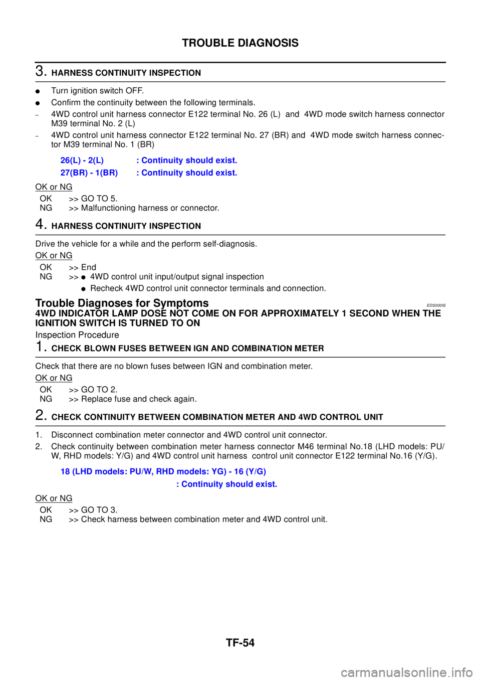
3.HARNESS CONTINUITY INSPECTION
lTurn ignition switch OFF.
lConfirm the continuity between the following terminals.
–4WD control unit harness connector E122 terminal No. 26 (L) and 4WD mode switch harness connector
M39 terminal No. 2 (L)
–4WD control unit harness connector E122 terminal No. 27 (BR) and 4WD mode switch harness connec-
tor M39 terminal No. 1 (BR)
OK or NG
OK >> GO TO 5.
NG >> Malfunctioning harness or connector.
4.HARNESS CONTINUITY INSPECTION
Drive the vehicle for a while and the perform self-diagnosis.
OK or NG
OK >> End
NG >>
l4WD control unit input/output signal inspection
lRecheck 4WD control unit connector terminals and connection.
Trouble Diagnoses for SymptomsEDS000IS
4WD INDICATOR LAMP DOSE NOT COME ON FOR APPROXIMATELY 1 SECOND WHEN THE
IGNITION SWITCH IS TURNED TO ON
Inspection Procedure
1.CHECK BLOWN FUSES BETWEEN IGN AND COMBINATION METER
Check that there are no blown fuses between IGN and combination meter.
OK or NG
OK >> GO TO 2.
NG >> Replace fuse and check again.
2.CHECK CONTINUITY BETWEEN COMBINATION METER AND 4WD CONTROL UNIT
1. Disconnect combination meter connector and 4WD control unit connector.
2. Check continuity between combination meter harness connector M46 terminal No.18 (LHD models: PU/
W, RHD models: Y/G) and 4WD control unit harness control unit connector E122 terminal No.16 (Y/G).
OK or NG
OK >> GO TO 3.
NG >> Check harness between combination meter and 4WD control unit.26(L) - 2(L) : Continuity should exist.
27(BR) - 1(BR) : Continuity should exist.
18 (LHD models: PU/W, RHD models: YG) - 16 (Y/G)
: Continuity should exist.
Page 3025 of 3066
TROUBLE DIAGNOSIS
TF-55
C
E
F
G
H
I
J
K
L
MA
B
TF
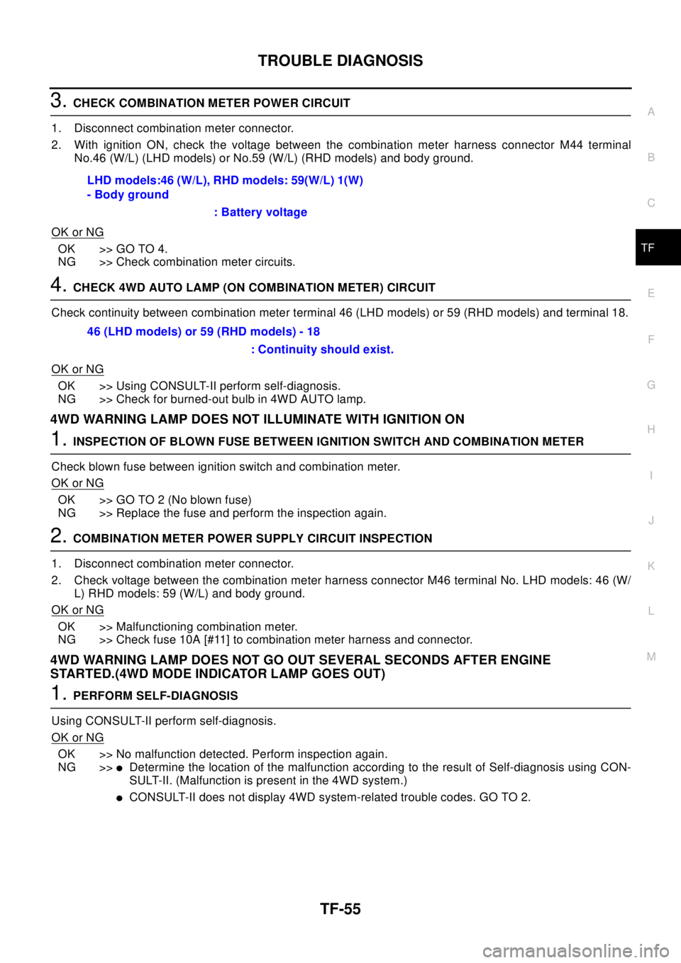
3.CHECK COMBINATION METER POWER CIRCUIT
1. Disconnect combination meter connector.
2. With ignition ON, check the voltage between the combination meter harness connector M44 terminal
No.46 (W/L) (LHD models) or No.59 (W/L) (RHD models) and body ground.
OK or NG
OK >> GO TO 4.
NG >> Check combination meter circuits.
4.CHECK 4WD AUTO LAMP (ON COMBINATION METER) CIRCUIT
Check continuity between combination meter terminal 46 (LHD models) or 59 (RHD models) and terminal 18.
OK or NG
OK >> Using CONSULT-II perform self-diagnosis.
NG >> Check for burned-out bulb in 4WD AUTO lamp.
4WD WARNING LAMP DOES NOT ILLUMINATE WITH IGNITION ON
1.INSPECTION OF BLOWN FUSE BETWEEN IGNITION SWITCH AND COMBINATION METER
Check blown fuse between ignition switch and combination meter.
OK or NG
OK >> GO TO 2 (No blown fuse)
NG >> Replace the fuse and perform the inspection again.
2.COMBINATION METER POWER SUPPLY CIRCUIT INSPECTION
1. Disconnect combination meter connector.
2. Check voltage between the combination meter harness connector M46 terminal No. LHD models: 46 (W/
L) RHD models: 59 (W/L) and body ground.
OK or NG
OK >> Malfunctioning combination meter.
NG >> Check fuse 10A [#11] to combination meter harness and connector.
4WD WARNING LAMP DOES NOT GO OUT SEVERAL SECONDS AFTER ENGINE
STARTED.(4WD MODE INDICATOR LAMP GOES OUT)
1.PERFORM SELF-DIAGNOSIS
Using CONSULT-II perform self-diagnosis.
OK or NG
OK >> No malfunction detected. Perform inspection again.
NG >>
lDetermine the location of the malfunction according to the result of Self-diagnosis using CON-
SULT-II. (Malfunction is present in the 4WD system.)
lCONSULT-II does not display 4WD system-related trouble codes. GO TO 2. LHD models:46 (W/L), RHD models: 59(W/L) 1(W)
- Body ground
: Battery voltage
46 (LHD models) or 59 (RHD models) - 18
: Continuity should exist.
Page 3042 of 3066

WW-4
FRONT WIPER AND WASHER SYSTEM
FRONT WIPER AND WASHER SYSTEM
PFP:28810
System DescriptionEKS0032N
WIPER OPERATION
The wiper switch is controlled by a lever built into the combination switch.
There are three wiper switch positions:
lLO speed
lHI speed
lINT (Intermittent)
With the ignition switch in the ON or START position, power is supplied
lthrough 20A fuse [No. 6, located in the fuse block (J/B)]
lto front wiper motor terminal 4.
LOW AND HIGH SPEED WIPER OPERATION
Ground is supplied to wiper and washer switch terminal 17 through body grounds E24 and E50.
When the wiper switch is placed in the LO position, ground is supplied
lthrough terminal 14 of the front wiper and washer switch
lto front wiper motor terminal 3.
With power and ground supplied, the wiper motor operates at low speed.
When the wiper switch is placed in the HI position, ground is supplied
lthrough terminal 16 of the front wiper and washer switch
lto wiper motor terminal 1.
With power and ground supplied, the wiper motor operates at high speed.
AUTO STOP OPERATION
With wiper switch turned OFF, wiper motor will continue to operate until wiper arms reach windshield base.
When wiper arms are not located at base of windshield with wiper switch OFF, ground is provided
lfrom terminal 14 of the front wiper and washer switch
lto front wiper motor terminal 3, in order to continue wiper motor operation at low speed.
Ground is also supplied
lthrough terminal 13 of the front wiper and washer switch
lto front wiper motor terminal 2
lthrough terminal 6 of the front wiper motor, and
lthrough body grounds E24 and E50.
When wiper arms reach base of windshield, front wiper motor terminals 4 and 2 are connected instead of ter-
minals 6 and 2. Wiper motor will then stop wiper arms at the STOP position.
INTERMITTENT OPERATION
The front wiper motor operates the wiper arms one time at low speed at a set interval of approximately 1 to 13
seconds. This feature is controlled by the wiper amplifier (INT SW) combined with front wiper and washer
switch.
When the wiper switch is placed in the INT position, ground is supplied to wiper amplifier.
The desired interval time is input to wiper amplifier (INT VR) from wiper volume switch combined with front
wiper and washer switch.
Then intermittent ground is supplied
lthrough wiper amplifier (OUTPUT) and
lthrough terminal 14 of front wiper and washer switch
lto front wiper motor terminal 3
The wiper motor operates at low speed at the desired interval.
WASHER OPERATION
With the ignition switch in the ON or START position, power is supplied
lthrough 20A fuse [No. 6, located in the fuse block (J/B)]
lto washer motor terminal 1.
Page 3057 of 3066
HEADLAMP WASHER
WW-19
C
D
E
F
G
H
I
J
L
MA
B
WW
HEADLAMP WASHERPFP:28620
System DescriptionEKS0036H
The headlamp washer is controlled by the headlamp washer timer. Power is supplied at all times. With power
and ground supplied, the headlamp washer motor operates.
lthrough 30A fusible link (letter E, located in fuse and fusible link box)
lto headlamp washer motor terminal 1, and
lthrough10Afuse(No.31,locatedinfuseandfusiblelinkbox)
lto lighting switch terminal 11.
lthrough 10A fuse [No. 11, located in fuse block (J/B)]
lto headlamp washer timer terminal 4.
Ground is supplied to headlamp washer timer terminal 5 through body grounds E24 and E50. When headlamp
washer switch is pushed during lighting switch is in 1st or 2ND position, ground is supplied
lto headlamp washer timer terminal 6
lthrough headlamp washer switch and body grounds M27 and M70, and
lto headlamp washer motor terminal 2
lthrough headlamp washer timer terminal 3.
With ignition switch in the ON or START position, power is supplied