Page 2884 of 3066

SC-12
CHARGING SYSTEM
CHARGING SYSTEM
PFP:00011
System DescriptionEKS00316
The alternator provides DC voltage to operate the vehicle's electrical system and to keep the battery charged.
The voltage output is controlled by the IC regulator.
Power is supplied at all times to alternator terminal 4 (S) through:
l120A (Gasoline engine models) or 100A (Diesel engine models) fusible link (letter A, located in the fuse
and fusible link box), and
l10A fuse (No.34, located in the fuse and fusible link box).
Terminal B supplies power to charge the battery and operate the vehicle's electrical system. Output voltage is
controlled by the IC regulator at terminal 4 (S) detecting the input voltage. The charging circuit is protected by
the 120A (Gasoline engine models) or 100A (Diesel engine models) link.
The alternator is grounded to the engine block.
With the ignition switch in the ON or START position, power is supplied
l10A fuse [No. 11, located in the fuse block (J/B)]
lto combination meter terminal 46 (LHD models) or terminal 59 (RHD models) for the charge warning
lamp.
Ground is supplied With power and ground supplied
lto terminal 64 (LHD models) or terminal 54 ( RHD models) of the combination meter
lthrough terminal 3 (L) of the alternator.
the charge warning lamp will illuminate. When the alternator is providing sufficient voltage with the engine run-
ning, the ground is opened and the charge warning lamp will go off.
If the charge warning lamp illuminates with the engine running, a fault is indicated.
Page 2886 of 3066
SC-14
CHARGING SYSTEM
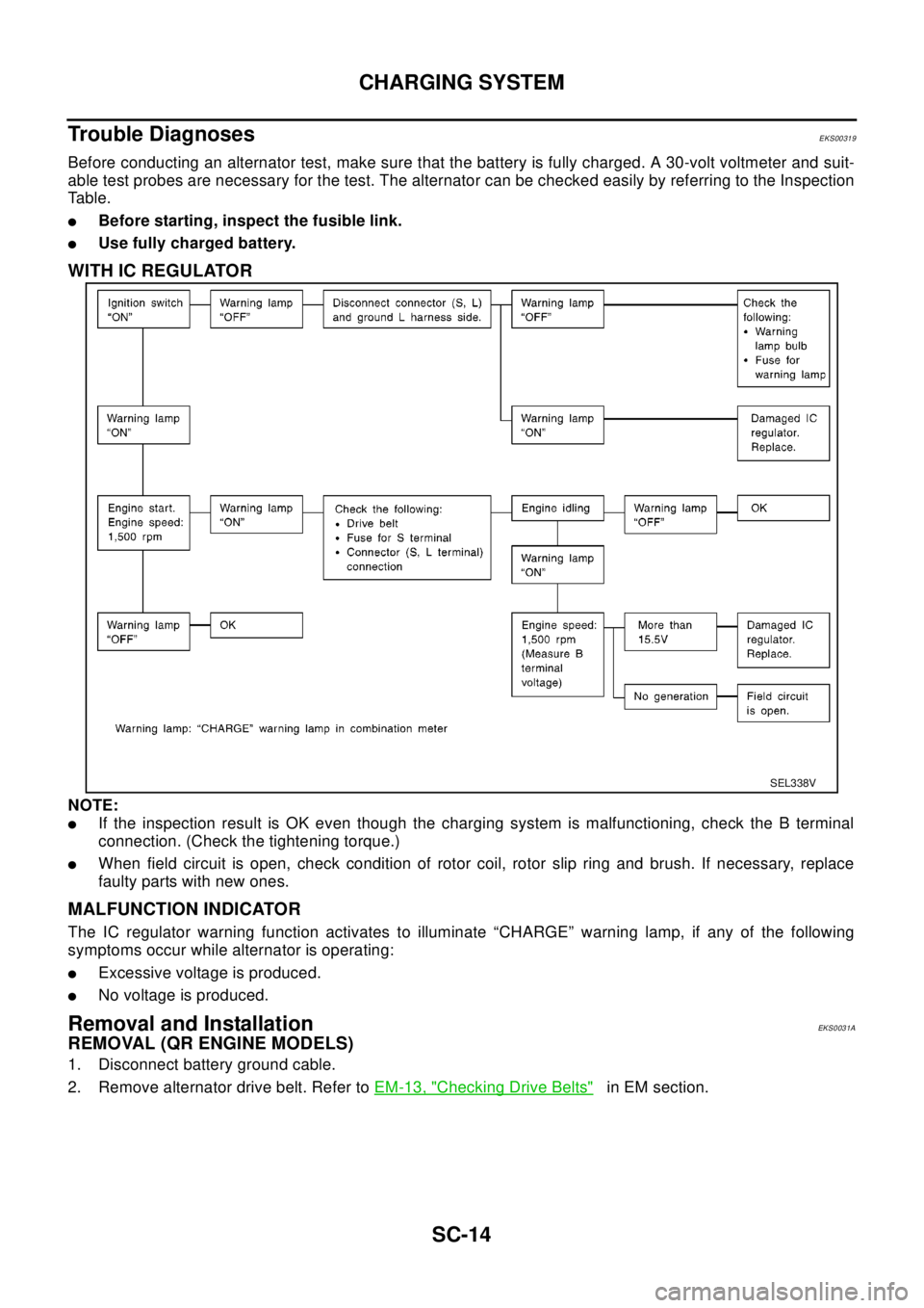
Trouble Diagnoses
EKS00319
Before conducting an alternator test, make sure that the battery is fully charged. A 30-volt voltmeter and suit-
able test probes are necessary for the test. The alternator can be checked easily by referring to the Inspection
Table.
lBefore starting, inspect the fusible link.
lUse fully charged battery.
WITH IC REGULATOR
NOTE:
lIf the inspection result is OK even though the charging system is malfunctioning, check the B terminal
connection. (Check the tightening torque.)
lWhen field circuit is open, check condition of rotor coil, rotor slip ring and brush. If necessary, replace
faulty parts with new ones.
MALFUNCTION INDICATOR
The IC regulator warning function activates to illuminate “CHARGE” warning lamp, if any of the following
symptoms occur while alternator is operating:
lExcessive voltage is produced.
lNo voltage is produced.
Removal and InstallationEKS0031A
REMOVAL (QR ENGINE MODELS)
1. Disconnect battery ground cable.
2. Remove alternator drive belt. Refer toEM-13, "
Checking Drive Belts"in EM section.
SEL338V
Page 2893 of 3066

STARTING SYSTEM
SC-21
C
D
E
F
G
H
I
J
L
MA
B
SC
STARTING SYSTEMPFP:00011
System DescriptionEKS0031F
M/T MODELS
Power is supplied at all times
lthrough 30A fusible link (letter J, located in the fuse and fusible link box)
lto ignition switch terminal 1.
With the ignition switch in the ON or START position, power is supplied
lfrom ignition switch terminal 5
lto starter motor harness connector terminal 1.
The starter motor plunger closes and provides a closed circuit between the battery and starter motor. The
starter motor is grounded to the engine block. With power and ground supplied, cranking occurs and the
engine starts.
A/T MODELS
Power is supplied at all times
lthrough 30A fusible link (letter J, located in the fuse and fusible link box)
lto ignition switch terminal 1.
With the ignition switch in the ON or START position, power is supplied
lthrough 10A fuse [No,13 located in the fuse block (J/B)]
lto park/neutral position relay terminal 1.
With the selector lever in the P or N position, ground is supplied
lto park/neutral position relay terminal 2
lthrough the park neutral position switch terminals 1 and 2,and
lthrough body grounds, F9 and F10.
Then park/neutral position relay is energized and power is supplied
lfrom park/neutral position relay terminal 3
lto starter motor harness connector terminal 1.
The starter motor plunger closes and provides a closed circuit between the battery and starter motor. The
starter motor is grounded to the engine block. With power and ground supplied, cranking occurs and the
engine starts.
Page 2896 of 3066
SC-24
STARTING SYSTEM
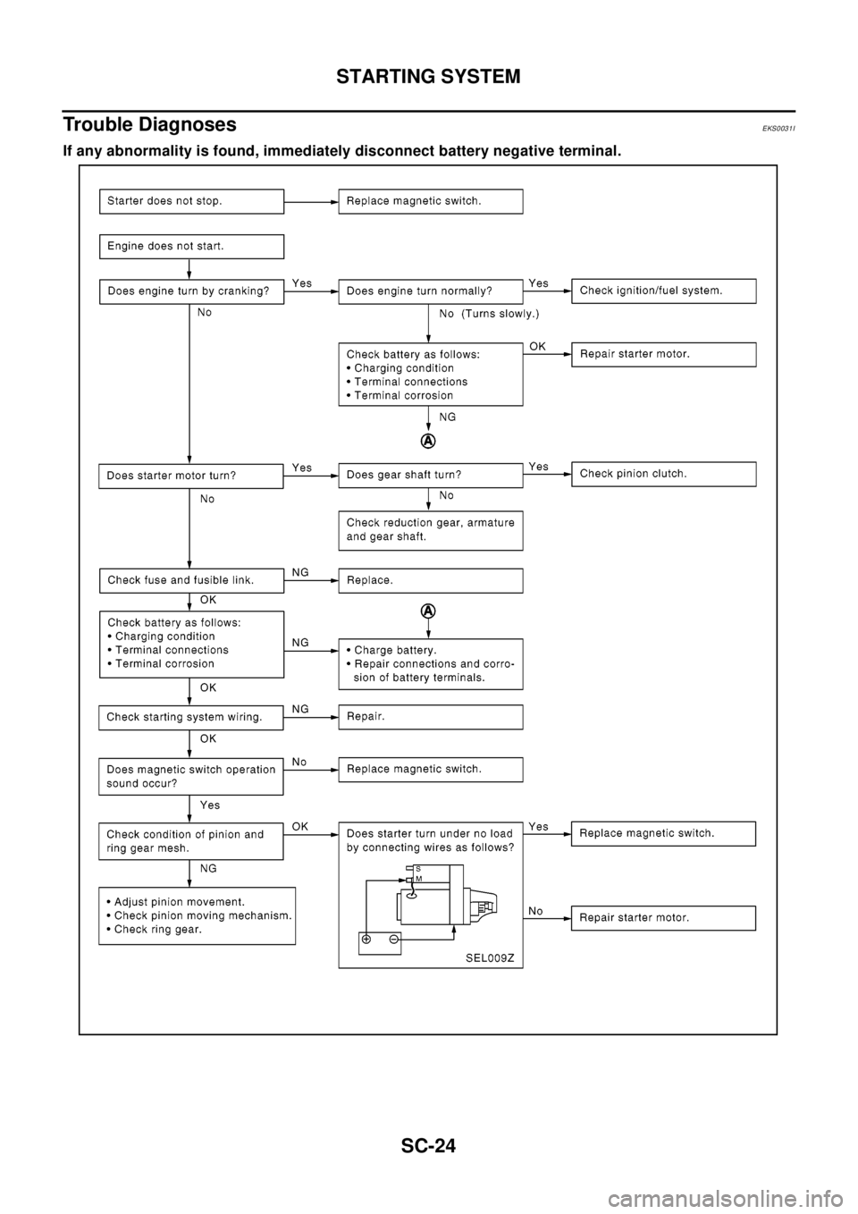
Trouble Diagnoses
EKS0031I
If any abnormality is found, immediately disconnect battery negative terminal.
Page 2897 of 3066
STARTING SYSTEM
SC-25
C
D
E
F
G
H
I
J
L
MA
B
SC
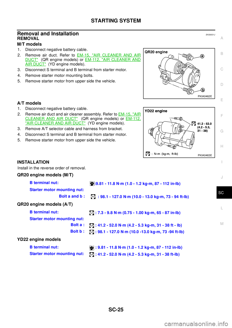
Removal and InstallationEKS0031J
REMOVAL
M/T models
1. Disconnect negative battery cable.
2. Remove air duct. Refer toEM-15, "
AIR CLEANER AND AIR
DUCT"(QR engine models) orEM-112, "AIR CLEANER AND
AIR DUCT"(YD engine models).
3. Disconnect S terminal and B terminal from starter motor.
4. Remove starter motor mounting bolts.
5. Remove starter motor from upper side the vehicle.
A/T models
1. Disconnect negative battery cable.
2. Remove air duct and air cleaner assembly. Refer toEM-15, "
AIR
CLEANER AND AIR DUCT"(QR engine models) orEM-112,
"AIR CLEANER AND AIR DUCT"(YD engine models).
3. Remove A/T selector cable and harness from bracket.
4. Disconnect S terminal and B terminal from starter motor.
5. Remove starter motor from upper side the vehicle.
INSTALLATION
Install in the reverse order of removal.
QR20 engine models (M/T)
QR20 engine models (A/T)
YD22 engine models
PKIA0462E
PKIA0463E
Bterminalnut:
:9.81 - 11.8 N·m (1.0 - 1.2 kg-m, 87 - 112 in-lb)
Starter motor mounting nut:
Bolt a and b :
: 98.1 - 127.0 N·m (10.0 - 13.0 kg-m, 73 - 94 ft-lb)
Bterminalnut:
: 7.3 - 9.8 N·m (0.75 - 1.00 kg-m, 65 - 87 in-lb)
Starter motor mounting nut:
Bolt a :
: 41.2 - 52.0 N·m (4.2 - 5.3 kg-m, 31 - 38 ft - lb)
Bolt b :
: 98.1 - 127.0 N·m (10.0 -13.0 kg-m, 73 -94 ft-lb)
Bterminalnut:
: 9.81 - 11.8 N·m (1.0 - 1.2 kg-m, 87 - 112 in-lb)
Starter motor mounting nut:
: 41.2 - 52.0 N·m (4.2 - 5.3 kg-m, 31 - 38 ft-lb)
Page 2900 of 3066
SC-28
STARTING SYSTEM
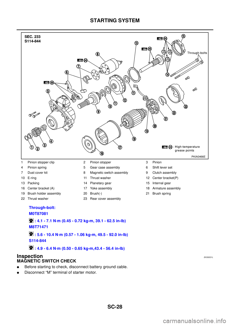
Inspection
EKS0031L
MAGNETIC SWITCH CHECK
lBefore starting to check, disconnect battery ground cable.
lDisconnect “M” terminal of starter motor.
1 Pinion stopper clip 2 Pinion stopper 3 Pinion
4 Pinion spring 5 Gear case assembly 6 Shift lever set
7 Dust cover kit 8 Magnetic switch assembly 9 Clutch assembly
10 E-ring 11 Thrust washer 12 Center bracket(P)
13 Packing 14 Planetary gear 15 Internal gear
16 Center bracket (A) 17 Yoke assembly 18 Armature assembly
19 Brush holder assembly 20 Brush(-) 21 Brush spring
22 Thrust washer 23 Rear cover assembly
Through-bolt:
M0T87081
: 4.1 - 7.1 N·m (0.45 - 0.72 kg-m, 39.1 - 62.5 in-lb)
M8T71471
: 5.6 - 10.4 N·m (0.57 - 1.06 kg-m, 49.5 - 92.0 in-lb)
S114-844
: 4.9 - 6.4 N·m (0.50 - 0.65 kg-m,43.4 - 56.4 in-lb)
PKIA0466E
Page 2906 of 3066

SC-34
SERVICE DATA AND SPECIFICATIONS (SDS)
SERVICE DATA AND SPECIFICATIONS (SDS)
PFP:00030
BatteryEKS0031Q
StarterEKS0031R
AlternatorEKS0031S
Applied modelQR20 engine
YD22 engine
Standard Option
Type 55D23L 80D26L 110D26L
Capacity V-AH 12-48 12-55 12-70
Ty p eS114-844 M0T87081 M8T71471
HITACHI make MITSUBISHI make
Reduction
Applied model QR20 engine YD22 engine
System voltage V12
No-loadTerminal voltage V 11.0
Current A Less than 90 Less than 90 Less than 145
Revolution rpm More than 2,700 More than 2,500 More than 3,300
Minimum diameter of commutator mm (in) 28.0 (1.102) 28.8 (1.134) 31.4 (1.236)
Minimum length of brush mm (in) 10.5 (0.413) 7.0 (0.276) 11.0 (0.433)
Brush spring tension N (kg, lb) 16.2(1.65, 3.64)15.0 - 20.4(1.5 - 2.1, 3.4
-4.6)26.7 - 36.1(2.7 - 3.7, 6.0
-8.2)
Clearance between bearing metal and armature
shaft mm (in)Less than 0.2 (0.008) —
Clearance “l” between pinion front edge and pinion
stopper mm (in)0.3 - 2.5 (0.012 - 0.098) 0.5 - 2.0(0.020 - 0.079) —
Movement “l” in height of pinion assembly mm (in) — 0.5 - 2.0(0.020 - 0.079)
Ty p eLR1110-713 A3TB0771
HITACHI make MITSUBISHI make
Applied model QR20 engine YD22 engine
Nominal rating V-A 12-110 12-90
Ground polarityNegative
Minimum revolutions under no-load (When 13.5V is
applied) rpmLess than 1,100 Less than 1,300
Hot output current (When 13.5V is applied) A/rpmMore than35/1,300
More than91/2,500
More than110/5,000More than29/1,300
More than76/2,500
More than88/5,000
Regulated output voltage V 14.1 - 14.7
Minimum length of brush mm (in) More than 6.0 (0.236) More than 5.0 (0.197)
Brush spring pressure N (g, oz) 1.0 - 3.43 (102 - 350, 3.60 - 12.34) 4.8 - 6.0 (490 - 610, 17.28 - 21.51)
Slip ring minimum diameter mm (in) More than 26.0 (1.024) More than 22.1 (0.870)
Rotor coil resistance at 20°(68°F)W2.31 2.1 - 2.5
Page 2925 of 3066
PRECAUTIONS
SRS-3
C
D
E
F
G
I
J
K
L
MA
B
SRS
PRECAUTIONSPFP:00001
Supplemental Restraint System (SRS) “AIR BAG” and “SEAT BELT PRE-TEN-
SIONER”
EHS000BG
The Supplemental Restraint System such as “AIR BAG” and “SEAT BELT PRE-TENSIONER” used along with
a front seat belt, helps to reduce the risk or severity of injury to the driver and front passenger for certain types
of collision.
WA RN ING:
lTo avoid rendering the SRS inoperative, which could increase the risk of personal injury or death
in the event of a collision which would result in air bag inflation, all maintenance should be per-
formed by an authorized NISSAN/INFINITI dealer.
lImproper maintenance, including incorrect removal and installation of the SRS, can lead to per-
sonal injury caused by unintentional activation of the system.
lDo not use electrical test equipment on any circuit related to the SRS unless instructed to in this
Service Manual. SRS wiring harnesses can be identified by yellow harness connector.
Precautions for SRS “AIR BAG” and “SEAT BELT PRE-TENSIONER” ServiceEHS000BH
lDo not use electrical test equipment to check SRS circuits unless instructed to in this Service Manual.
lBefore servicing the SRS, turn ignition switch “OFF”, disconnect battery ground cable and wait at least 3
minutes.
For approximately 3 minutes after the cables is removed, it is still possible for the air bag and seat belt
pre-tensioner to deploy. Therefore, do not work on any SRS connectors or wires until at least 3 minutes
have passed.
lDiagnosis sensor unit must always be installed with their arrow marks “Ü” pointing towards the front of the
vehicle for proper operation. Also check diagnosis sensor unit for cracks, deformities or rust before instal-
lation and replace as required.
lThe spiral cable must be aligned with the neutral position since its rotations are limited. Do not attempt to
turn steering wheel or column after removal of steering gear.
lHandle air bag module carefully. Always place driver and front passenger air bag modules with the pad
side facing upward and place front side air bag module standing with stud bolt side setting bottom.
lConduct self-diagnosis to check entire SRS for proper function after replacing any components.
lAfter air bag inflates, the front instrument panel assembly should be replaced if damaged.
Trouble Diagnosis PrecautionEHS000BI
Whenyoureadwiringdiagrams,refertothefollowings:
l“HOW TO READ WIRING DIAGRAMS” in GI section
lPG-2, "POWER SUPPLY ROUTING"in PG section
When you perform trouble diagnosis, refer to the followings:
l“HOW TO FOLLOW TEST GROUP IN TROUBLE DIAGNOSIS” in GI section
l“HOW TO PERFORM EFFICIENT DIAGNOSIS FOR AN ELECTRICAL INCIDENT” in GI section
Check for any service bulletins before servicing the vehicle.