Page 2861 of 3066

COIL SPRING AND STRUT
RSU-9
C
D
F
G
H
I
J
K
L
MA
B
RSU
ASSEMBLY
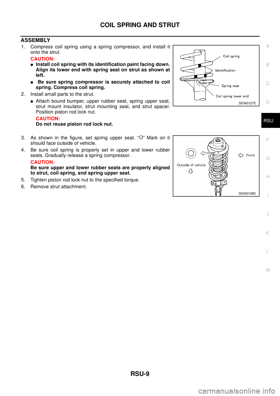
1. Compress coil spring using a spring compressor, and install it
onto the strut.
CAUTION:
lInstall coil spring with its identification paint facing down.
Align its lower end with spring seat on strut as shown at
left.
lBe sure spring compressor is securely attached to coil
spring. Compress coil spring.
2. Install small parts to the strut.
lAttach bound bumper, upper rubber seat, spring upper seat,
strut mount insulator, strut mounting seal, and strut spacer.
Position piston rod lock nut.
CAUTION:
Do not reuse piston rod lock nut.
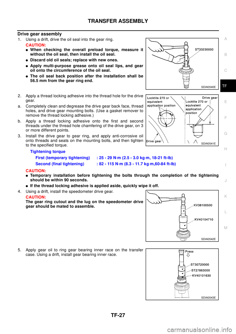
3. As shown in the figure, set spring upper seat. “ ” Mark on it
should face outside of vehicle.
4. Be sure coil spring is properly set in upper and lower rubber
seats. Gradually release a spring compressor.
CAUTION:
Be sure upper and lower rubber seats are properly aligned
to strut, coil spring, and spring upper seat.
5. Tighten piston rod lock nut to the specified torque.
6. Remove strut attachment.SEIA0127E
SEIA0128E
Page 2997 of 3066

TRANSFER ASSEMBLY
TF-27
C
E
F
G
H
I
J
K
L
MA
B
TF
Drive gear assembly
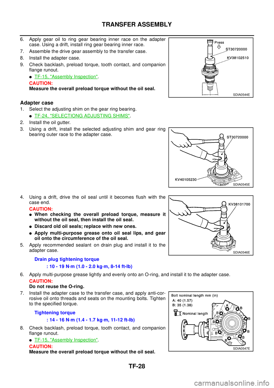
1. Using a drift, drive the oil seal into the gear ring.
CAUTION:
lWhen checking the overall preload torque, measure it
without the oil seal, then install the oil seal.
lDiscard old oil seals; replace with new ones.
lApply multi-purpose grease onto oil seal lips, and gear
oil onto the circumference of the oil seal.
lThe oil seal back position after the installation shall be
56.5 mm from the gear ring end.
2. Apply a thread locking adhesive into the thread hole for the drive
gear.
a. Completely clean and degrease the drive gear back face, thread
holes, and drive gear mounting bolts. (Use a gasket remover to
remove the thread locking adhesive.)
b. Apply a thread locking adhesive onto the first and second
threads under the thread hole chamfering of the drive gear, on 3
or more different points.
3. Install the drive gear to gear ring, and apply anti-corrosive oil
onto threads and seats on the mounting bolts, and then tighten
to the specified torque.
CAUTION:
lTemporary installation before tightening the bolts through the completion of the tightening
should be within 90 seconds.
lIf the thread locking adhesive is applied aside, quickly wipe it off.
4. Using a drift, install the speedometer drive gear.
CAUTION:
The gear ring cutout and the lug on the speedometer drive
gear should be mated to assemble.
5. Apply gear oil to ring gear bearing inner race on the transfer
case. Using a drift, install gear bearing inner race.
SDIA0540E
Tightening torque
First (temporary tightening) : 25 - 29 N·m (2.5 - 3.0 kg·m, 18-21 ft-lb)
Second (final tightening) : 82 - 115 N·m (8.3 - 11.7 kg·m,60-84 ft-lb)
SDIA0541E
SDIA0542E
SDIA0543E
Page 2998 of 3066

TF-28
TRANSFER ASSEMBLY
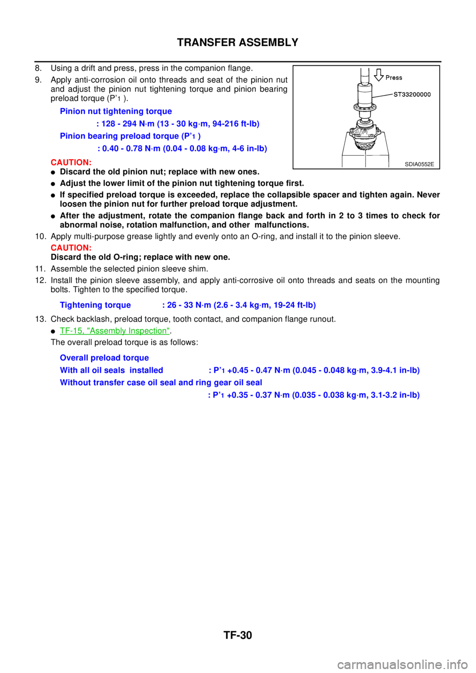
6. Apply gear oil to ring gear bearing inner race on the adapter
case. Using a drift, install ring gear bearing inner race.
7. Assemble the drive gear assembly to the transfer case.
8. Install the adapter case.
9. Check backlash, preload torque, tooth contact, and companion
flange runout.
lTF-15, "Assembly Inspection".
CAUTION:
Measure the overall preload torque without the oil seal.
Adapter case
1. Select the adjusting shim on the gear ring bearing.
lTF-24, "SELECTIONG ADJUSTING SHIMS".
2. Install the oil gutter.
3. Using a drift, install the selected adjusting shim and gear ring
bearing outer race to the adapter case.
4. Using a drift, drive the oil seal until it becomes flush with the
case end.
CAUTION:
lWhen checking the overall preload torque, measure it
without the oil seal, then install the oil seal.
lDiscard old oil seals; replace with new ones.
lApply multi-purpose grease onto oil seal lips, and gear
oil onto the circumference of the oil seal.
5. Apply recommended sealant on drain plug and install it to the
adapter case.
6. Apply multi-purpose grease lightly and evenly onto an O-ring, and install it to the adapter case.
CAUTION:
Do not reuse the O-ring.
7. Install the adapter case to the transfer case, and apply anti-cor-
rosive oil onto threads and seats on the mounting bolts. Tighten
to the specified torque.
8. Check backlash, preload torque, tooth contact, and companion
flange runout.
lTF-15, "Assembly Inspection".
CAUTION:
Measure the overall preload torque without the oil seal.
SDIA0544E
SDIA0545E
Drain plug tightening torque
: 10 - 19 N·m (1.0 - 2.0 kg·m, 8-14 ft-lb)
Tightening torque
: 14 - 16 N·m (1.4 - 1.7 kg·m, 11-12 ft-lb)
SDIA0546E
SDIA0547E
Page 3000 of 3066

TF-30
TRANSFER ASSEMBLY
8. Using a drift and press, press in the companion flange.
9. Apply anti-corrosion oil onto threads and seat of the pinion nut
and adjust the pinion nut tightening torque and pinion bearing
preload torque (P’
1).
CAUTION:
lDiscard the old pinion nut; replace with new ones.
lAdjust the lower limit of the pinion nut tightening torque first.
lIf specified preload torque is exceeded, replace the collapsible spacer and tighten again. Never
loosen the pinion nut for further preload torque adjustment.
lAfter the adjustment, rotate the companion flange back and forth in 2 to 3 times to check for
abnormal noise, rotation malfunction, and other malfunctions.
10. Apply multi-purpose grease lightly and evenly onto an O-ring, and install it to the pinion sleeve.
CAUTION:
Discard the old O-ring; replace with new one.
11. Assemble the selected pinion sleeve shim.
12. Install the pinion sleeve assembly, and apply anti-corrosive oil onto threads and seats on the mounting
bolts. Tighten to the specified torque.
13. Check backlash, preload torque, tooth contact, and companion flange runout.
lTF-15, "Assembly Inspection".
The overall preload torque is as follows:Pinion nut tightening torque
: 128 - 294 N·m (13 - 30 kg·m, 94-216 ft-lb)
Pinion bearing preload torque (P’
1)
: 0.40 - 0.78 N·m (0.04 - 0.08 kg·m, 4-6 in-lb)
Tightening torque : 26 - 33 N·m (2.6 - 3.4 kg·m, 19-24 ft-lb)
Overall preload torque
With all oil seals installed : P’
1+0.45 - 0.47 N·m (0.045 - 0.048 kg·m, 3.9-4.1 in-lb)
Without transfer case oil seal and ring gear oil seal
:P’
1+0.35 - 0.37 N·m (0.035 - 0.038 kg·m, 3.1-3.2 in-lb)
SDIA0552E
Page:
< prev 1-8 9-16 17-24