2003 NISSAN X-TRAIL seats
[x] Cancel search: seatsPage 2149 of 3066
![NISSAN X-TRAIL 2003 Electronic Repair Manual CYLINDER HEAD
EM-179
[YD22DDTi]
C
D
E
F
G
H
I
J
K
L
MA
EM
5. Remove valve oil seals using valve oil seal puller.
6. Remove valve spring seats.
7. Before removing valve spring seats, perform valve seat NISSAN X-TRAIL 2003 Electronic Repair Manual CYLINDER HEAD
EM-179
[YD22DDTi]
C
D
E
F
G
H
I
J
K
L
MA
EM
5. Remove valve oil seals using valve oil seal puller.
6. Remove valve spring seats.
7. Before removing valve spring seats, perform valve seat](/manual-img/5/57402/w960_57402-2148.png)
CYLINDER HEAD
EM-179
[YD22DDTi]
C
D
E
F
G
H
I
J
K
L
MA
EM
5. Remove valve oil seals using valve oil seal puller.
6. Remove valve spring seats.
7. Before removing valve spring seats, perform valve seat contact
check. Refer toEM-181, "
Va l v e S e a t C o n ta ct".
8. Before removing valve guides, perform valve guide clearance
check. Refer toEM-180, "
Valve Guide Clearance".
ASEMBLY
1. Install valve guides. Refer toEM-180, "Valve Guide Clearance".
2. Install valve seats. Refer toEM-181, "
Valve Seat Replacement".
3. Using valve oil seal drift, install valve oil seals referring to the
dimension shown in the figure.
lDifferent parts are used for valve location, Identify by the rub-
ber color.
4. Install valve spring seats.
5. Install valves.
lInstall the valves with bigger outer diameter to intake valve
side.
lNote that valve layout here is different from that of conventional engine.
6. Install valve spring.
lWhen installing valve spring, make sure that a smaller pitch
side (identification paint-applied side) faces the cylinder head.
7. Install valve spring retainers.
8. Using valve spring compressor, compress valve springs.
Then install valve collets using magnetic hand.
lAfter installing valve collets, tap the stem end using a plastic
hammer, and check the installation status.
9. Install valve lifters and adjusting shims to the same positions as
before.
INSPECTION AFTER DISASSEMBLY
Cylinder Head Distortion
Using straightedge and feeler gauge, check the bottom of the cylin-
der head for distortion.
JEM153G
For intake : Black
For exhaust : Brown
JEM165G
Identification color : Yellow
FEM080
Limit : 0.04 mm (0.0016 in)
SEM496G
Page 2152 of 3066
![NISSAN X-TRAIL 2003 Electronic Repair Manual EM-182
[YD22DDTi]
CYLINDER HEAD
2. Machine cylinder head inner diameter at valve seat installation
position.
3. Heat cylinder head to approximately 110 to 130°C(230to
266°F) in oil bath.
4. After co NISSAN X-TRAIL 2003 Electronic Repair Manual EM-182
[YD22DDTi]
CYLINDER HEAD
2. Machine cylinder head inner diameter at valve seat installation
position.
3. Heat cylinder head to approximately 110 to 130°C(230to
266°F) in oil bath.
4. After co](/manual-img/5/57402/w960_57402-2151.png)
EM-182
[YD22DDTi]
CYLINDER HEAD
2. Machine cylinder head inner diameter at valve seat installation
position.
3. Heat cylinder head to approximately 110 to 130°C(230to
266°F) in oil bath.
4. After cooling valve seats sufficiently with dry ice, press fit it to cylinder head.
CAUTION:
Do not touch the cooled valve seats directly by hand.
5. Using valve seat cutter, finish processing referring to the dimen-
sions shown in the figure.
CAUTION:
When using valve seat cutter, grasp cutter handle with both
hands, press cutter onto contacting face all around, and cut
thoroughly. If cutter is pressed unevenly or repeatedly, the
valve seat surface may be damaged.
6. Using compound, perform valve fitting.
7. Check again to make sure that contacting status is satisfactory.
For details, Refer toEM-181, "
Valve Seat Contact". Machining dimension:
Intake
30.500 - 30.516 mm (1.2008 - 1.2014 in) dia.
Exhaust
29.500 - 29.516 mm (1.1614 - 1.1620 in) dia.
SEM795A
FEM075
SBIA0197E
Page 2247 of 3066
FSU-8
COIL SPRING AND SHOCK ABSORBER
COIL SPRING AND SHOCK ABSORBER
PFP:54302
Removal and InstallationEES00074
REMOVAL
1. Remove tires. Remove brake caliper and hung it aside.
CAUTION:
Avoid depressing brake pedal with brake caliper removed.
2. Remove electrical wires of ABS wheel speed sensor from strut.
3. Remove brake hose lock plate.
4. Remove mounting bolts and nuts securing steering knuckle to strut.
5. Remove mounting nuts on top of strut and remove upper mounting plate and strut from vehicle.
INSTALLATION
lRefer toFSU-5, "Components"in “Front Suspension Assembly” for tightening torque. Tighten in the
reverse order of removal.
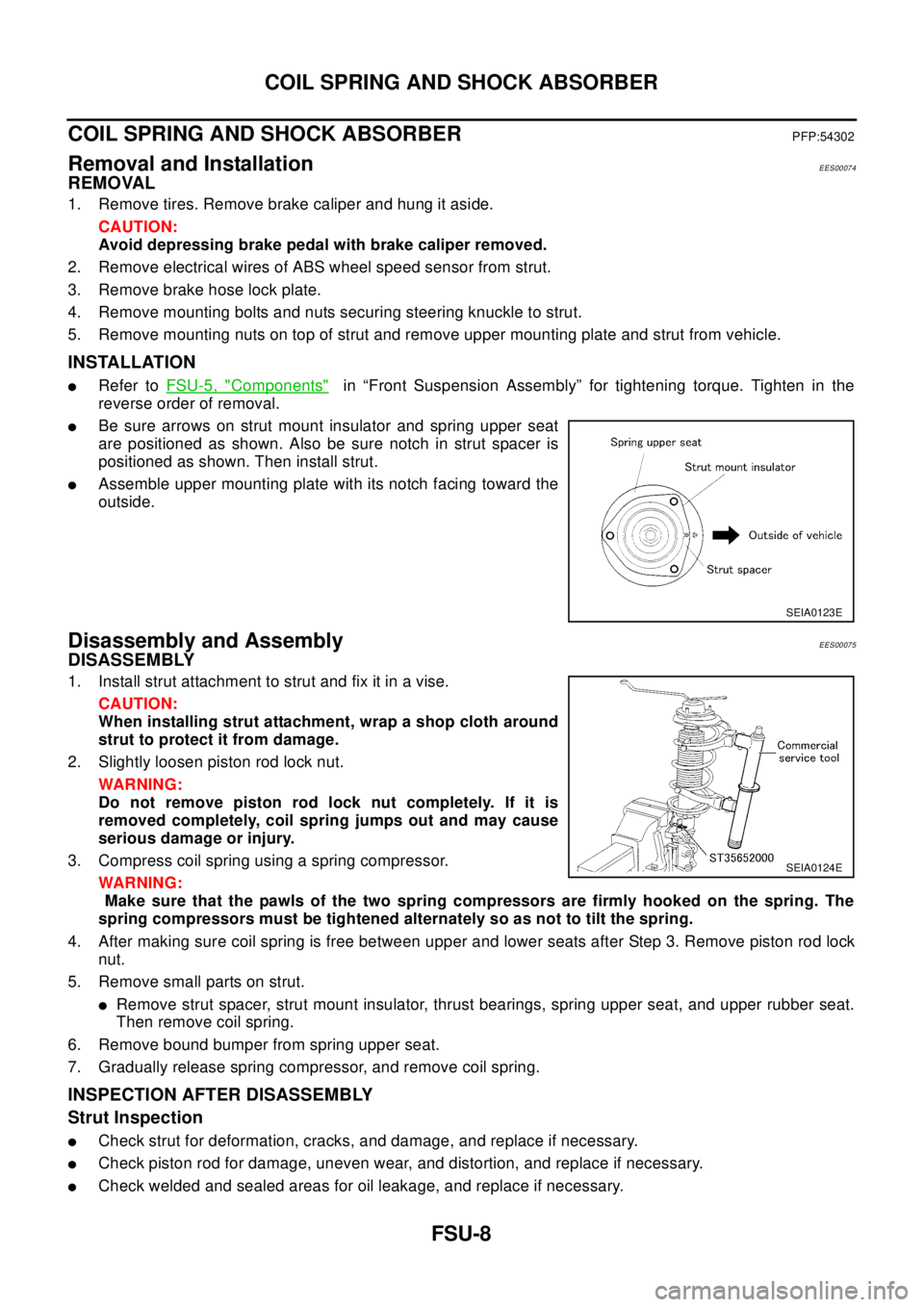
lBe sure arrows on strut mount insulator and spring upper seat
are positioned as shown. Also be sure notch in strut spacer is
positioned as shown. Then install strut.
lAssemble upper mounting plate with its notch facing toward the
outside.
Disassembly and AssemblyEES00075
DISASSEMBLY
1. Install strut attachment to strut and fix it in a vise.
CAUTION:
When installing strut attachment, wrap a shop cloth around
strut to protect it from damage.
2. Slightly loosen piston rod lock nut.
WAR NIN G:
Do not remove piston rod lock nut completely. If it is
removed completely, coil spring jumps out and may cause
serious damage or injury.
3. Compress coil spring using a spring compressor.
WAR NIN G:
Make sure that the pawls of the two spring compressors are firmly hooked on the spring. The
spring compressors must be tightened alternately so as not to tilt the spring.
4. After making sure coil spring is free between upper and lower seats after Step 3. Remove piston rod lock
nut.
5. Remove small parts on strut.
lRemove strut spacer, strut mount insulator, thrust bearings, spring upper seat, and upper rubber seat.
Then remove coil spring.
6. Remove bound bumper from spring upper seat.
7. Gradually release spring compressor, and remove coil spring.
INSPECTION AFTER DISASSEMBLY
Strut Inspection
lCheck strut for deformation, cracks, and damage, and replace if necessary.
lCheck piston rod for damage, uneven wear, and distortion, and replace if necessary.
lCheck welded and sealed areas for oil leakage, and replace if necessary.
SEIA0123E
SEIA0124E
Page 2496 of 3066
MA-4
DESCRIPTION
DESCRIPTION
PFP:00000
Pre-delivery Inspection ItemsELS000AK
Shown below are Pre-delivery Inspection Items required for the new vehicle. It is recommended that
necessary items other than those listed here be added, paying due regard to the conditions in each
country.
Perform applicable items on each model. Consult text of this section for specifications.
UNDER HOOD — engine off
Radiator coolant level and coolant hose connections for leaks
Battery fluid level, specific gravity and conditions of battery terminals
Drive belts tension
Fuel filter for water or dusts (Diesel only), and fuel lines and connections for leaks
Engine oil level and oil leaks
Clutch and brake reservoir fluid level and fluid lines for leaks
Windshield and rear window washer and headlamp cleaner reservoir fluid level
Power steering reservoir fluid level and hose connections for leaks
ON INSIDE AND OUTSIDE
Remove front spring/strut spacer (If applicable)
Operation of all instruments, gauges, lights and accessories
Operation of horn(s), wiper and washer
Steering lock for operation
Check air conditioner for gas leaks
Front and rear seats, and seat belts for operation
All moldings, trims and fittings for fit and alignment
All windows for operation and alignment
Hood, trunk lid, door panels for fit and alignment
Latches, keys and locks for operation
Weatherstrips for adhesion and fit
Headlamp aiming
Tighten wheel nuts (Inc. inner nuts if applicable)
Tire pressure (Inc. spare tire)
Check front wheels for toe-in
Install clock/voltmeter/room lamp fuse (If applicable)
Install deodorizing filter to air conditioner (If applicable)
Remove wiper blade protectors (If applicable)
UNDER BODY
Manual transmission/transaxle, transfer and differential gear oil level
Brake and fuel lines and oil/fluid reservoirs for leaks
Tighten bolts and nuts of steering linkage and gear box, suspension, propeller shafts and drive shafts
Tighten rear body bolts and nuts (Models with wooden bed only)
ROAD TEST
Clutch operation
Parking brake operation
Service brake operation
Automatic transmission/transaxle shift timing and kickdown
Steering control and returnability
Engine performance
Squeaks and rattles
ENGINE OPERATING AND HOT
Adjust idle speed
Automatic transmission/transaxle fluid level
Page 2666 of 3066
MTC-30
DUCTS AND GRILLES
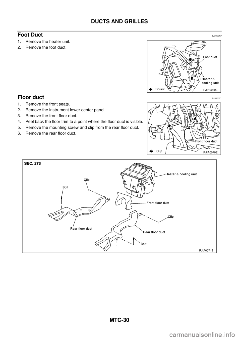
Foot Duct
EJS000Y0
1. Remove the heater unit.
2. Remove the foot duct.
Floor ductEJS000Y1
1. Remove the front seats.
2. Remove the instrument lower center panel.
3. Remove the front floor duct.
4. Peel back the floor trim to a point where the floor duct is visible.
5. Remove the mounting screw and clip from the rear floor duct.
6. Remove the rear floor duct.
RJIA0069E
RJIA0070E
RJIA0071E
Page 2820 of 3066
RF-8
SUNROOF
SUNROOF UNIT
Removal
CAUTION:
lRemoval and installation of sunroof unit require 2 workers.
lWhen taking sunroof unit out, use shop cloths to protect seats and trim from damage.
lAfter installing sunroof unit and glass lid, be sure to carry out the leak test to confirm there is no
more leakage.
1. Remove headlining. Refer toEI-29, "
HEADLINING"
2. Disconnect drain hoses (4).
3. Disconnect interior lamp harness.
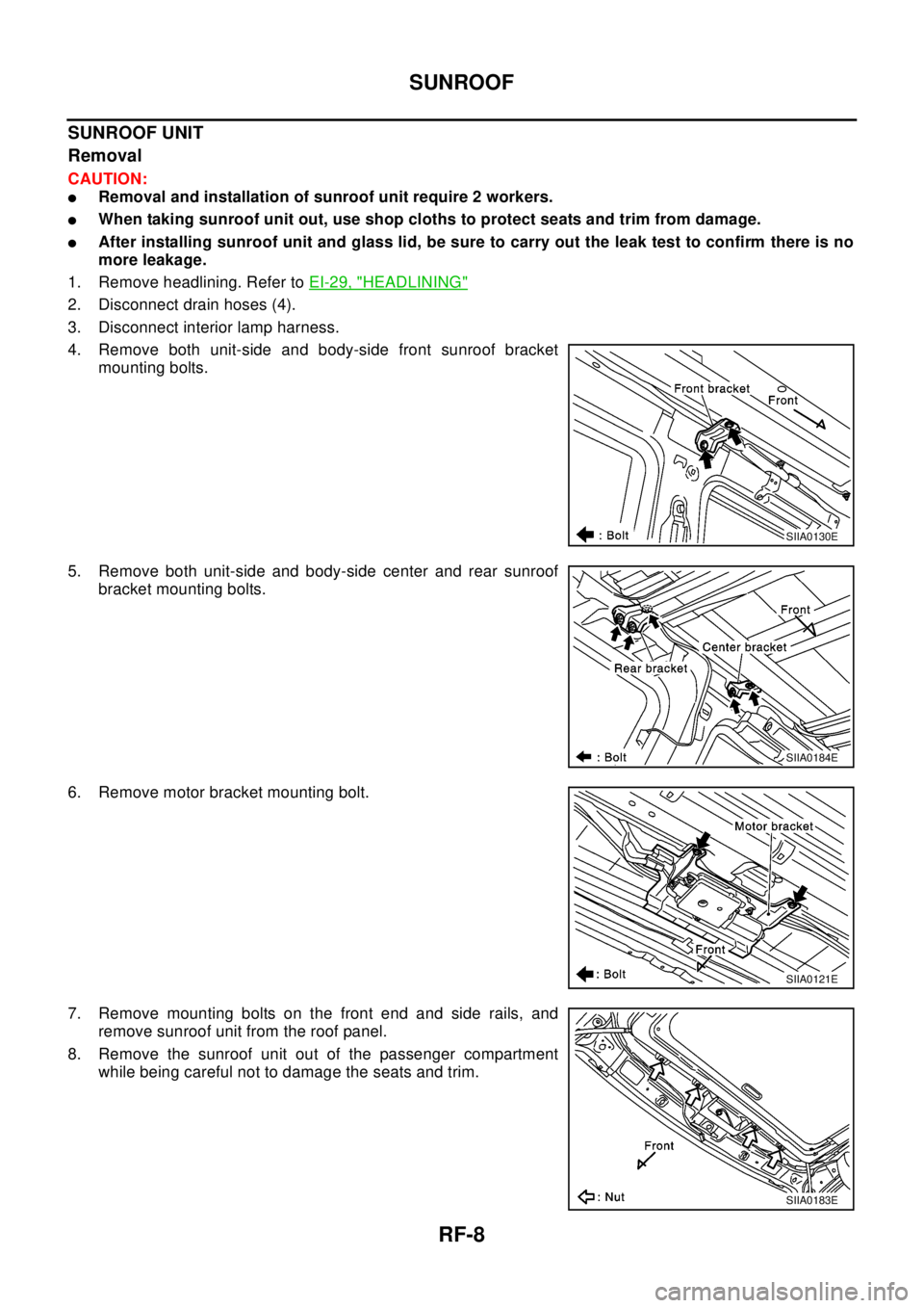
4. Remove both unit-side and body-side front sunroof bracket
mounting bolts.
5. Remove both unit-side and body-side center and rear sunroof
bracket mounting bolts.
6. Remove motor bracket mounting bolt.
7. Remove mounting bolts on the front end and side rails, and
remove sunroof unit from the roof panel.
8. Remove the sunroof unit out of the passenger compartment
while being careful not to damage the seats and trim.
SIIA0130E
SIIA0184E
SIIA0121E
SIIA0183E
Page 2847 of 3066
REAR FINAL DRIVE ASSEMBLY
RFD-25
C
E
F
G
H
I
J
K
L
MA
B
RFD
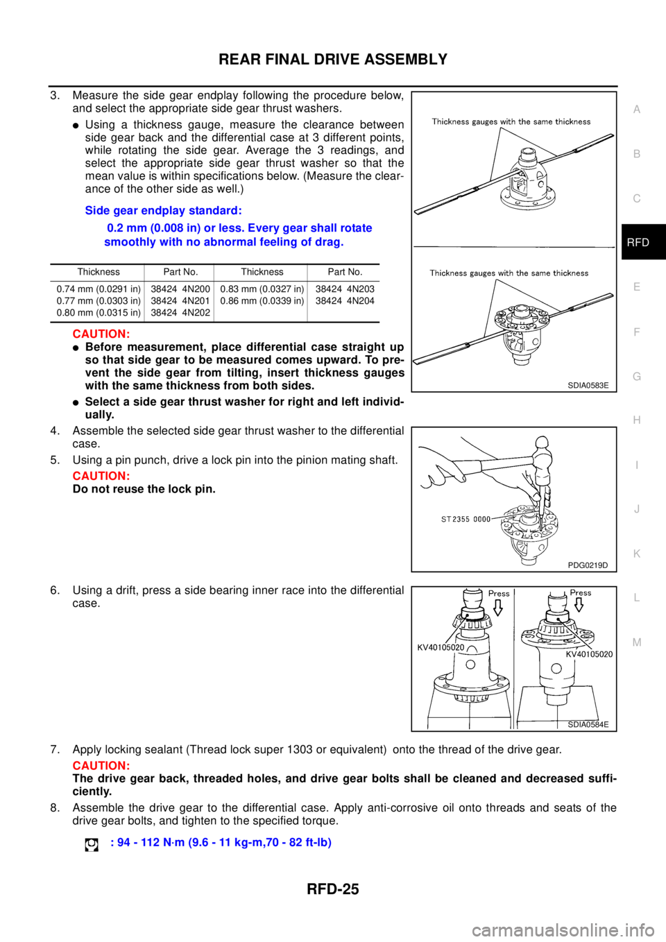
3. Measure the side gear endplay following the procedure below,
and select the appropriate side gear thrust washers.
lUsing a thickness gauge, measure the clearance between
side gear back and the differential case at 3 different points,
while rotating the side gear. Average the 3 readings, and
select the appropriate side gear thrust washer so that the
mean value is within specifications below. (Measure the clear-
ance of the other side as well.)
CAUTION:
lBefore measurement, place differential case straight up
so that side gear to be measured comes upward. To pre-
vent the side gear from tilting, insert thickness gauges
with the same thickness from both sides.
lSelect a side gear thrust washer for right and left individ-
ually.
4. Assemble the selected side gear thrust washer to the differential
case.
5. Using a pin punch, drive a lock pin into the pinion mating shaft.
CAUTION:
Do not reuse the lock pin.
6. Using a drift, press a side bearing inner race into the differential
case.
7. Apply locking sealant (Thread lock super 1303 or equivalent) onto the thread of the drive gear.
CAUTION:
The drive gear back, threaded holes, and drive gear bolts shall be cleaned and decreased suffi-
ciently.
8. Assemble the drive gear to the differential case. Apply anti-corrosive oil onto threads and seats of the
drive gear bolts, and tighten to the specified torque.Side gear endplay standard:
0.2 mm (0.008 in) or less. Every gear shall rotate
smoothly with no abnormal feeling of drag.
Thickness Part No. Thickness Part No.
0.74 mm (0.0291 in)
0.77 mm (0.0303 in)
0.80 mm (0.0315 in)38424 4N200
38424 4N201
38424 4N2020.83 mm (0.0327 in)
0.86 mm (0.0339 in)38424 4N203
38424 4N204
SDIA0583E
PDG0219D
SDIA0584E
:94-112N·m(9.6-11kg-m,70-82ft-lb)
Page 2860 of 3066
RSU-8
COIL SPRING AND STRUT
COIL SPRING AND STRUT
PFP:55302
Removal and InstallationEES0007H
REMOVAL
1. Remove tires.
2. Remove brake hose lock plate and remove brake hose from strut.
3. Remove mounting nuts and washers on upper portion of stabilizer connecting rod.
4. Remove strut-to-axle housing mounting bolts and nuts.
5. Remove luggage side lower finisher in luggage compartment.Remove mounting nuts on upper portion of
strut. Then remove strut from vehicle.
INSTALLATION
lRefer toRSU-5, "Components"for tightening torque. Install in the reverse order of removal.
Disassembly and AssemblyEES0007I
DISASSEMBLY
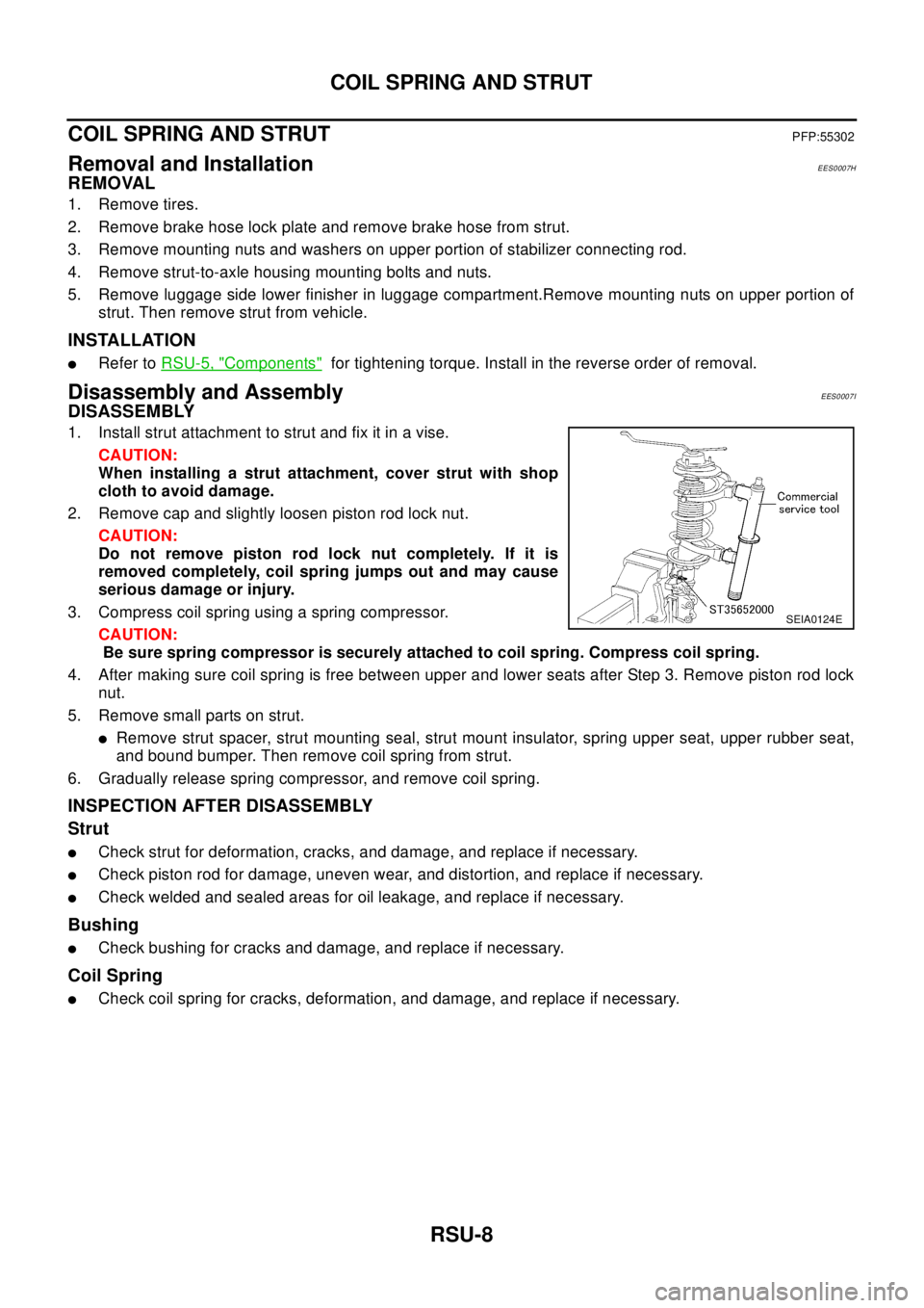
1. Install strut attachment to strut and fix it in a vise.
CAUTION:
When installing a strut attachment, cover strut with shop
cloth to avoid damage.
2. Remove cap and slightly loosen piston rod lock nut.
CAUTION:
Do not remove piston rod lock nut completely. If it is
removed completely, coil spring jumps out and may cause
serious damage or injury.
3. Compress coil spring using a spring compressor.
CAUTION:
Be sure spring compressor is securely attached to coil spring. Compress coil spring.
4. After making sure coil spring is free between upper and lower seats after Step 3. Remove piston rod lock
nut.
5. Remove small parts on strut.
lRemove strut spacer, strut mounting seal, strut mount insulator, spring upper seat, upper rubber seat,
and bound bumper. Then remove coil spring from strut.
6. Gradually release spring compressor, and remove coil spring.
INSPECTION AFTER DISASSEMBLY
Strut
lCheck strut for deformation, cracks, and damage, and replace if necessary.
lCheck piston rod for damage, uneven wear, and distortion, and replace if necessary.
lCheck welded and sealed areas for oil leakage, and replace if necessary.
Bushing
lCheck bushing for cracks and damage, and replace if necessary.
Coil Spring
lCheck coil spring for cracks, deformation, and damage, and replace if necessary.
SEIA0124E