2003 NISSAN X-TRAIL change wheel
[x] Cancel search: change wheelPage 1722 of 3066
![NISSAN X-TRAIL 2003 Electronic Repair Manual EC-608
[QR (WITHOUT EURO-OBD)]
IVT CONTROL SOLENOID VALVE
IVT CONTROL SOLENOID VALVE
PFP:23796
DescriptionEBS00BM1
SYSTEM DESCRIPTION
This mechanism hydraulically controls cam phases continuously with NISSAN X-TRAIL 2003 Electronic Repair Manual EC-608
[QR (WITHOUT EURO-OBD)]
IVT CONTROL SOLENOID VALVE
IVT CONTROL SOLENOID VALVE
PFP:23796
DescriptionEBS00BM1
SYSTEM DESCRIPTION
This mechanism hydraulically controls cam phases continuously with](/manual-img/5/57402/w960_57402-1721.png)
EC-608
[QR (WITHOUT EURO-OBD)]
IVT CONTROL SOLENOID VALVE
IVT CONTROL SOLENOID VALVE
PFP:23796
DescriptionEBS00BM1
SYSTEM DESCRIPTION
This mechanism hydraulically controls cam phases continuously with the fixed operating angle of the intake
valve.
The ECM receives signals such as crankshaft position, camshaft position, engine speed, and engine coolant
temperature. Then, the ECM sends ON/OFF pulse duty signals to the intake valve timing control solenoid
valve depending on driving status. This makes it possible to control the shut/open timing of the intake valve to
increase engine torque in low/mid speed range and output in high-speed range.
COMPONENT DESCRIPTION
Intake valve timing control solenoid valve is activated by ON/OFF
pulse duty (ratio) signals from the ECM.
The intake valve timing control solenoid valve changes the oil
amount and direction of flow through intake valve timing control unit
or stops oil flow.
The longer pulse width advances valve angle.
The shorter pulse width retards valve angle.
When ON and OFF pulse widths become equal, the solenoid valve
stops oil pressure flow to fix the intake valve angle at the control
position.
CONSULT-II Reference Value in Data Monitor ModeEBS00B9A
Specification data are reference values.
Sensor Input signal to ECM function ECM Actuator
Crankshaft position sensor (POS)
Engine speed
Intake valve
timing controlIntake valve timing control
solenoid valve Camshaft position sensor (PHASE)
Engine coolant temperature sensor Engine coolant temperature
Wheel sensor Vehicle speed
PBIB0540E
PBIB0195E
MONITOR ITEM CONDITION SPECIFICATION
INT/V SOL (B1)
lEngine: After warming up
lShift lever: N
lAir conditioner switch: OFF
lNo-loadIdle 0% - 2%
When revving engine up to 2,000 rpm
quicklyApprox. 0% - 50%
Page 2212 of 3066
FAX-16
FRONT DRIVE SHAFT
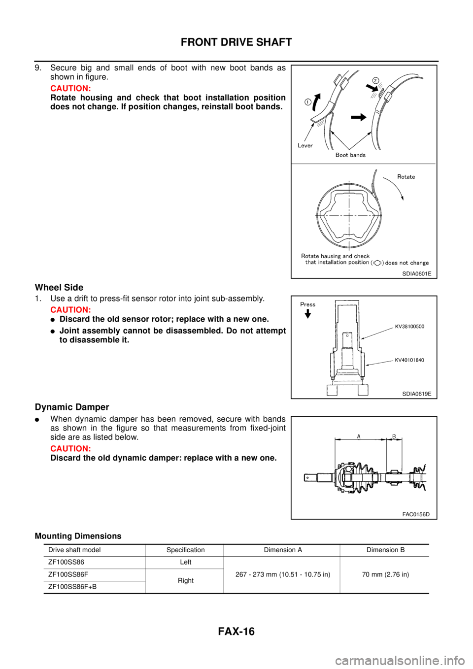
9. Secure big and small ends of boot with new boot bands as
shown in figure.
CAUTION:
Rotate housing and check that boot installation position
does not change. If position changes, reinstall boot bands.
Wheel Side
1. Use a drift to press-fit sensor rotor into joint sub-assembly.
CAUTION:
lDiscard the old sensor rotor; replace with a new one.
lJoint assembly cannot be disassembled. Do not attempt
to disassemble it.
Dynamic Damper
lWhen dynamic damper has been removed, secure with bands
as shown in the figure so that measurements from fixed-joint
side are as listed below.
CAUTION:
Discard the old dynamic damper: replace with a new one.
Mounting Dimensions
SDIA0601E
SDIA0619E
FAC0156D
Drive shaft model Specification Dimension A Dimension B
ZF100SS86 Left
267 - 273 mm (10.51 - 10.75 in) 70 mm (2.76 in) ZF100SS86F
Right
ZF100SS86F+B
Page 2258 of 3066
PRECAUTIONS
GI-5
lUse only the fluids and lubricants specified in this manual.
lUse approved bonding agent, sealants or their equivalents when required.
lUse tools and recommended special tools where specified for safe and efficient service repairs.
lWhen repairing the fuel, oil, water, vacuum or exhaust systems, check all affected lines for leaks.
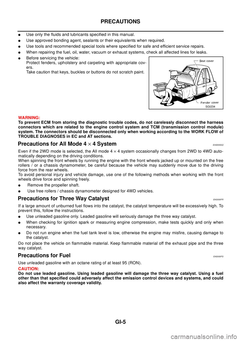
lBefore servicing the vehicle:
Protect fenders, upholstery and carpeting with appropriate cov-
ers.
Take caution that keys, buckles or buttons do not scratch paint.
WA RN ING:
To prevent ECM from storing the diagnostic trouble codes, do not carelessly disconnect the harness
connectors which are related to the engine control system and TCM (transmission control module)
system. The connectors should be disconnected only when working according to the WORK FLOW of
TROUBLE DIAGNOSES in EC and AT sections.
Precautions for All Mode 4´4 SystemEAS000GQ
Even if the 2WD mode is selected, the All mode 4´4 system occasionally changes from 2WD to 4WD auto-
matically depending on the driving conditions.
When spinning the front wheels by running the engine with the front wheels jacked up or mounted on the free
rollers / or a chassis dynamometer, be careful because the vehicle may suddenly move due to the driving
force from the rear wheels.
To avoid personal injury and vehicle damage, use one of the following methods when working with the front
wheels drive force and spinning freely.
lRemove the propeller shaft.
lUse free rollers / chassis dynamometer designed for 4WD vehicles.
Precautions for Three Way CatalystEAS000FR
If a large amount of unburned fuel flows into the catalyst, the catalyst temperature will be excessively high. To
prevent this, follow the instructions.
lUse unleaded gasoline only. Leaded gasoline will seriously damage the three way catalyst.
lWhen checking for ignition spark or measuring engine compression, make tests quickly and only when
necessary.
lDo not run engine when the fuel tank level is low, otherwise the engine may misfire, causing damage to
the catalyst.
Do not place the vehicle on flammable material. Keep flammable material off the exhaust pipe and the three
way catalyst.
Precautions for FuelEAS000FS
Use unleaded gasoline with an octane rating of at least 95 (RON).
CAUTION:
Do not use leaded gasoline. Using leaded gasoline will damage the three way catalyst. Using a fuel
other than that specified could adversely affect the emission control devices and systems, and could
also affect the warranty coverage validity.
SGI234
Page 2498 of 3066
MA-6
GENERAL MAINTENANCE
GENERAL MAINTENANCE
PFP:00000
General MaintenanceELS000AL
General maintenance includes those items which should be checked during the normal day-to-day operation
of the vehicle. They are essential if the vehicle is to continue operating properly. The owners can perform the
checks and inspections themselves or they can have their NISSAN dealers do them for a nominal charge.
OUTSIDE THE VEHICLE
The maintenance items listed here should be performed from time to time, unless otherwise specified.
INSIDE THE VEHICLE
The maintenance items listed here should be checked on a regular basis, such as when performing periodic maintenance, cleaning the
vehicle, etc.
UNDER THE HOOD AND VEHICLE
The maintenance items listed here should be checked periodically e.g. each time you check the engine oil or refuel.Item Reference page
TiresCheck the pressure with a gauge periodically when at a service station, includ-
ing the spare, and adjust to the specified pressure if necessary. Check carefully
for damage, cuts or excessive wear.—
Windshield wiper
bladesCheck for cracks or wear if not functioning correctly. —
Doors and engine
hoodCheck that all doors, the engine hood, the trunk lid and back door operate prop-
erly. Also ensure that all latches lock securely. Lubricate if necessary. Make sure
that the secondary latch keeps the hood from opening when the primary latch is
released.
When driving in areas using road salt or other corrosive materials, check for
lubrication frequently.BL-4
,BL-8
Tire rotationTires should be rotated every 5,000 km (3,000 miles).MA-38
Item Reference page
LampsMake sure that the headlamps, stop lamps, tail lamps, turn signal lamps, and
other lamps are all operating properly and installed securely. Also check head-
lamp aim.—
Warning lamps and
chimesMake sure that all warning lamps and buzzers/chimes are operating properly. —
Steering wheelCheck that it has the specified play.
Check for changes in the steering conditions, such as excessive free play, hard
steering or strange noises.
Free play: Less than 35 mm (1.38 in)—
Seat beltsCheck that all parts of the seat belt system (e.g. buckles, anchors, adjusters and
retractors) operate properly and smoothly, and are installed securely. Check the
belt webbing for cuts, fraying, wear or damage.SB-3
Item Reference page
Windshield washer
fluidCheck that there is adequate fluid in the tank. —
Engine coolant levelCheck the coolant level when the engine is cold.CO-9
(QR20DE)
CO-30
(YD22DDTi)
Engine oil levelCheck the level after parking the vehicle (on level ground) and turning off the
engine.LU-7
(QR20DE)
LU-18
(YD22DDTi)
Brake and clutch fluid
levelsMake sure that the brake and clutch fluid levels are between the “MAX” and
“MIN” lines on the reservoir.MA-35
,MA-38
BatteryCheck the fluid level in each cell. It should be between the “MAX” and “MIN”
lines.—
Page 2765 of 3066
POWER STEERING FLUID
PS-5
C
D
E
F
H
I
J
K
L
MA
B
PS
POWER STEERING FLUIDPFP:KLF20
Checking Fluid LevelEGS0004B
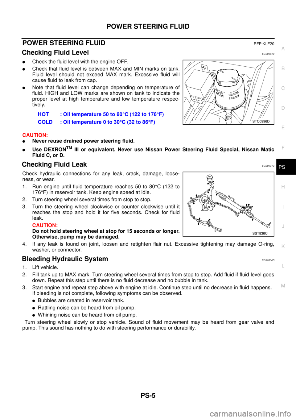
lCheck the fluid level with the engine OFF.
lCheck that fluid level is between MAX and MIN marks on tank.
Fluid level should not exceed MAX mark. Excessive fluid will
cause fluid to leak from cap.
lNote that fluid level can change depending on temperature of
fluid. HIGH and LOW marks are shown on tank to indicate the
proper level at high temperature and low temperature respec-
tively.
CAUTION:
lNever reuse drained power steering fluid.
lUse DEXRONTMIII or equivalent. Never use Nissan Power Steering Fluid Special, Nissan Matic
Fluid C, or D.
Checking Fluid LeakEGS0004C
Check hydraulic connections for any leak, crack, damage, loose-
ness, or wear.
1. Run engine until fluid temperature reaches 50 to 80°C (122 to
176°F) in reservoir tank. Keep engine speed at idle.
2. Turn steering wheel several times from stop to stop.
3. Turn the steering wheel clockwise or counter clockwise until it
reaches the stop and hold it for five seconds. Check for fluid
leak.
CAUTION:
Do not hold steering wheel at stop for 15 seconds or longer.
Otherwise, pump may be damaged.
4. If any leak is found on joint, loosen and retighten flair nut. Excessive tightening may damage O-ring,
washer, or connector.
Bleeding Hydraulic SystemEGS0004D
1. Lift vehicle.
2. Fill tank up to MAX mark. Turn steering wheel several times from stop to stop. Add fluid if fluid level goes
down. Repeat this step until there is no fluid decrease and no bubble in tank.
3. Start engine and repeat step above with engine at idle. Continue step until no decrease in fluid happens.
If bleeding is not complete, following symptoms can be observed.
lBubbles are created in reservoir tank.
lRattling noise can be heard from oil pump.
lWhiningnoisecanbeheardfromoilpump.
Turn steering wheel slowly or stop vehicle. Sound of fluid movement may be heard from gear valve and
pump. This sound has nothing to do with steering performance or durability.HOT : Oil temperature 50 to 80°C (122 to 176°F)
COLD : Oil temperature 0 to 30°C(32to86°F)
STC0996D
SST836C
Page 2809 of 3066
REAR DRIVE SHAFT
RAX-13
C
E
F
G
H
I
J
K
L
MA
B
RAX
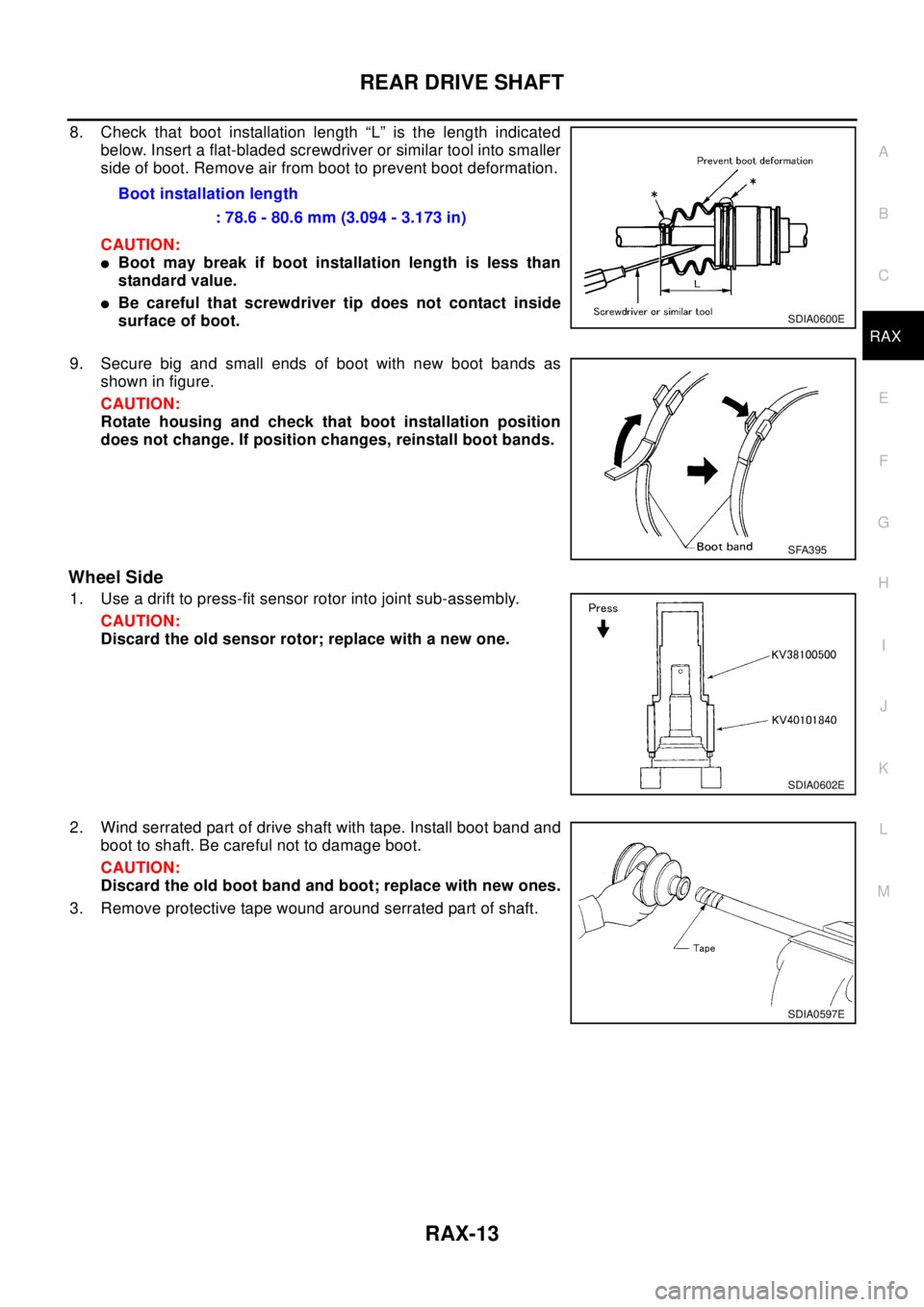
8. Check that boot installation length “L” is the length indicated
below. Insert a flat-bladed screwdriver or similar tool into smaller
side of boot. Remove air from boot to prevent boot deformation.
CAUTION:
lBoot may break if boot installation length is less than
standard value.
lBe careful that screwdriver tip does not contact inside
surface of boot.
9. Secure big and small ends of boot with new boot bands as
shown in figure.
CAUTION:
Rotate housing and check that boot installation position
does not change. If position changes, reinstall boot bands.
Wheel Side
1. Use a drift to press-fit sensor rotor into joint sub-assembly.
CAUTION:
Discard the old sensor rotor; replace with a new one.
2. Wind serrated part of drive shaft with tape. Install boot band and
boot to shaft. Be careful not to damage boot.
CAUTION:
Discard the old boot band and boot; replace with new ones.
3. Remove protective tape wound around serrated part of shaft.Boot installation length
: 78.6 - 80.6 mm (3.094 - 3.173 in)
SDIA0600E
SFA395
SDIA0602E
SDIA0597E
Page 2824 of 3066
RFD-2
PRECAUTIONS
PRECAUTIONS
PFP:00001
CautionEDS00056
lBefore starting diagnosis of the vehicle, understand symptoms well. Perform correct and systematic oper-
ations.
lCheck for the correct installation status prior to removal or disassembly. When mating marks are required,
be sure they do not interfere with the function of the parts they are applied to.
lCarry out an overhaul in a clean work place. Using a dust proof room is recommended.
lBefore disassembly, using steam or white gasoline, completely remove sand and mud from the exterior of
the unit, preventing them from entering into the unit during disassembly or assembly.
lCheck appearance of the disassembled parts for damage, deformation, and abnormal wear. If a malfunc-
tion is detected, replace it with a new one.
lNormally replace lock pins, oil seals, and bearings with new ones every time they are removed.
lIn principle, tighten bolts or nuts gradually in several steps working diagonally from inside to outside. If
tightening sequence is specified, observe it.
lClean and flush the parts sufficiently and blow them dry.
lBe careful not to damage the sliding surfaces and mating surfaces.
lWhen applying sealant, remove the old sealant from the mounting surface; then remove any moisture, oil,
and foreign materials from the application and mounting surfaces.
lAlways use shop paper for cleaning the inside of components.
lAvoid using cotton gloves or a shop cloth to prevent entering of lint.
lDuring assembly, observe the specified tightening torque, and apply new differential oil, Vaseline, or Nis-
san MP Special Grease No. 2, as specified for each vehicle, when necessary.
lDo not reuse drained oil. Discard waste oil after oil changes or part treatment in accordance with local
laws and regulations.
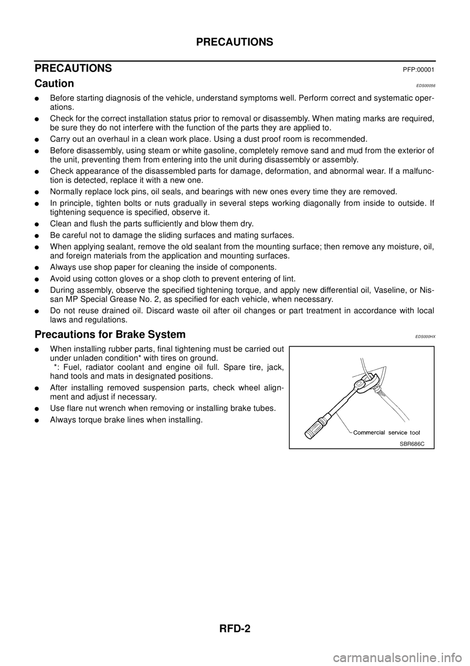
Precautions for Brake SystemEDS000HX
lWhen installing rubber parts, final tightening must be carried out
under unladen condition* with tires on ground.
*: Fuel, radiator coolant and engine oil full. Spare tire, jack,
hand tools and mats in designated positions.
lAfter installing removed suspension parts, check wheel align-
ment and adjust if necessary.
lUse flare nut wrench when removing or installing brake tubes.
lAlways torque brake lines when installing.
SBR686C
Page 2923 of 3066
SRS-1
SUPPLEMENTAL RESTRAINT SYSTEM (SRS)
H RESTRAINTS
CONTENTS
C
D
E
F
G
I
J
K
L
M
SECTION
A
B
SRS
SUPPLEMENTAL RESTRAINT SYSTEM (SRS)
PRECAUTIONS .......................................................... 3
Supplemental Restraint System (SRS) “AIR BAG”
and “SEAT BELT PRE-TENSIONER” ...................... 3
Precautions for SRS “AIR BAG” and “SEAT BELT
PRE-TENSIONER” Service ..................................... 3
Trouble Diagnosis Precaution .................................. 3
PREPARATION ........................................................... 4
Special Service Tool ................................................. 4
Commercial Service Tool ......................................... 4
SUPPLEMENTAL RESTRAINT SYSTEM (SRS) ....... 5
SRS Configuration ................................................... 5
Front Seat Belt Pre-tensioner with Load Limiter ...... 5
Front Side Air Bag .................................................... 5
TROUBLE DIAGNOSIS .............................................. 7
Trouble Diagnoses-Introduction ............................... 7
DIAGNOSIS FUNCTION ....................................... 7
HOW TO PERFORM TROUBLE DIAGNOSES
FOR QUICK AND ACCURATE REPAIR ............... 7
WORK FLOW ........................................................ 7
SRS Components Parts Location ............................. 9
Wiring Diagram — SRS — /LHD models ............... 10
Wiring Diagram-SRS-/RHD models ....................... 12
CONSULT-II FUNCTION ........................................ 14
DIAGNOSIS MODE FOR CONSULT-II ............... 14
HOW TO CHANGE SELF-DIAGNOSIS MODE
WITH CONSULT-II .............................................. 14
HOW TO ERASE SELF-DIAGNOSIS RESULTS... 14
SELF-DIAGNOSIS FUNCTION (WITHOUT CON-
SULT-II) .................................................................. 15
HOW TO CHANGE SELF-DIAGNOSIS MODE... 15
HOW TO ERASE SELF-DIAGNOSIS RESULTS... 15
SRS Operation Check ............................................ 15
DIAGNOSTIC PROCEDURE 1 ........................... 15
Trouble Diagnoses with CONSULT–II .................... 17
DIAGNOSTIC PROCEDURE 2 ........................... 17
DIAGNOSTIC PROCEDURE 3 ........................... 20
DIAGNOSTIC PROCEDURE 4 ........................... 20
Trouble Diagnoses Without CONSULT-II ............... 22
DIAGNOSTIC PROCEDURE 5 ........................... 22
WARNING LAMP FLASH CODE CHART ........... 23Trouble Diagnoses: “AIR BAG” Warning Lamp Does
Not Turn Off ............................................................ 25
DIAGNOSTIC PROCEDURE 6 ........................... 25
Trouble Diagnoses: “AIR BAG” Warning Lamp Does
Not Turn On ............................................................ 26
DIAGNOSTIC PROCEDURE 7 ........................... 26
DRIVER AIR BAG MODULE .................................... 27
Removal and Installation/With 4-Spoke Steering
Wheel ..................................................................... 27
REMOVAL ........................................................... 27
INSTALLATION ................................................... 28
Removal and Installation/With 3-Spoke Steering
Wheel ..................................................................... 29
REMOVAL ........................................................... 29
INSTALLATION ................................................... 30
SPIRAL CABLE ........................................................ 31
Removal and Installation ........................................ 31
REMOVAL ........................................................... 31
INSTALLATION ................................................... 32
Components Inspection .......................................... 32
FRONT PASSENGER AIR BAG MODULE .............. 33
Removal and Installation ........................................ 33
REMOVAL ........................................................... 33
INSTALLATION ................................................... 33
FRONT SIDE AIR BAG MODULE ............................ 35
Removal and Installation ........................................ 35
REMOVAL ........................................................... 35
INSTALLATION ................................................... 36
SIDE AIR BAG (SATELLITE) SENSOR ................... 37
Removal and Installation ........................................ 37
REMOVAL ........................................................... 37
INSTALLATION ................................................... 37
FRONT SEAT BELT PRE-TENSIONER ................... 38
Removal and Installation ........................................ 38
DIAGNOSIS SENSOR UNIT ..................................... 39
Removal and Installation ........................................ 39
REMOVAL ........................................................... 39
INSTALLATION ................................................... 39
ECU DISCRIMINATED NO. ................................ 39
DISPOSAL OF AIR BAG MODULE AND SEAT BELT