Page 866 of 3066
BR-32
REAR DISC BRAKE
4. Fix piston boot with retaining ring.
CAUTION:
lBe sure boot is securely engaged in groove on cylinder
body.
lDo not reuse retaining ring.
5. Connect sliding pins and sliding pin boots to torque member.
6. Connect torque member to axle assembly and tighten mounting
bolts to specified torque.
CAUTION:
Wipe oil and grease on axle assembly washer seats and torque
member mounting surface. Install torque member to axle
assembly.
7. Connect pads, pad retainers, shims, and shim covers to torque member and assemble cylinder body.
8. Tighten sliding pin bolts to the specified torque.
9. Connect brake hose to caliper assembly and tighten union bolts to the specified torque.
CAUTION:
Do not reuse union bolt copper washer.
10. After installing caliper assembly, refill with new brake fluid and bleed air. Refer toBR-10, "
Bleeding Brake
System"
SFIA0158E
Page 2208 of 3066
FAX-12
FRONT DRIVE SHAFT
lDo not allow drive shaft, with transaxle inserted, to hang down without support for counter
shaft, wheel joints, and other parts.
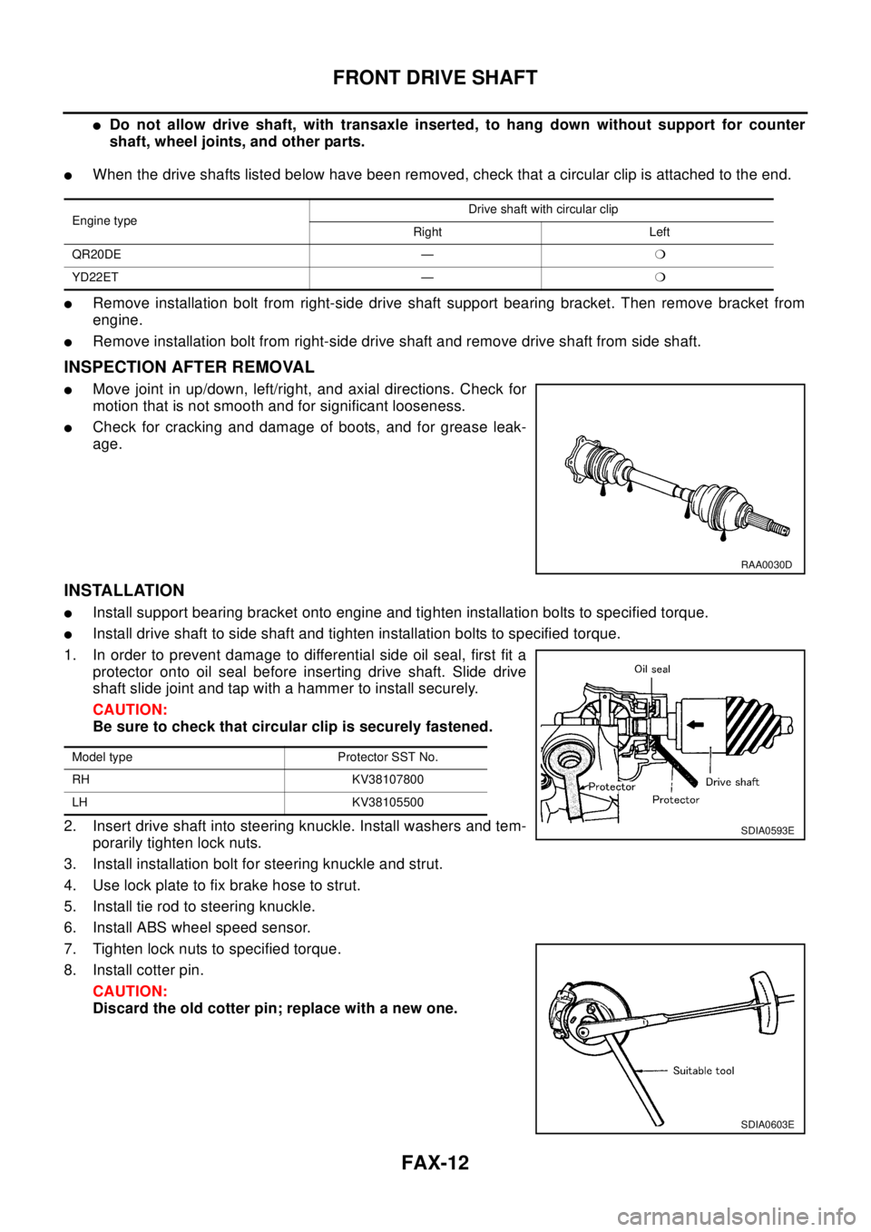
lWhen the drive shafts listed below have been removed, check that a circular clip is attached to the end.
lRemove installation bolt from right-side drive shaft support bearing bracket. Then remove bracket from
engine.
lRemove installation bolt from right-side drive shaft and remove drive shaft from side shaft.
INSPECTION AFTER REMOVAL
lMove joint in up/down, left/right, and axial directions. Check for
motion that is not smooth and for significant looseness.
lCheck for cracking and damage of boots, and for grease leak-
age.
INSTALLATION
lInstall support bearing bracket onto engine and tighten installation bolts to specified torque.
lInstall drive shaft to side shaft and tighten installation bolts to specified torque.
1. In order to prevent damage to differential side oil seal, first fit a
protector onto oil seal before inserting drive shaft. Slide drive
shaft slide joint and tap with a hammer to install securely.
CAUTION:
Be sure to check that circular clip is securely fastened.
2. Insert drive shaft into steering knuckle. Install washers and tem-
porarily tighten lock nuts.
3. Install installation bolt for steering knuckle and strut.
4. Use lock plate to fix brake hose to strut.
5. Install tie rod to steering knuckle.
6. Install ABS wheel speed sensor.
7. Tighten lock nuts to specified torque.
8. Install cotter pin.
CAUTION:
Discard the old cotter pin; replace with a new one.
Engine typeDrive shaft with circular clip
Right Left
QR20DE —m
YD22ET —m
RAA0030D
Model type Protector SST No.
RH KV38107800
LH KV38105500
SDIA0593E
SDIA0603E
Page 2209 of 3066
FRONT DRIVE SHAFT
FAX-13
C
E
F
G
H
I
J
K
L
MA
B
FA X
Disassembly and AssemblyEDS0005V
DISASSEMBLY
Transaxle Side
1. Remove boot band.
2. Fix shaft to bench vise.
CAUTION:
When fixing shaft to bench vise, be sure to protect it with a copper or aluminum sheet.
3. Put match marks on shaft and spider assembly.
CAUTION:
Use paint or similar substance for alignment marks. Do not
scratch the surface.
4. Remove snap ring. Remove spider assembly from shaft.
5. Remove boot from shaft.
6. Remove dynamic damper from shaft.
SDIA0610E
SDIA0594E
Page 2210 of 3066
FAX-14
FRONT DRIVE SHAFT
Wheel Side
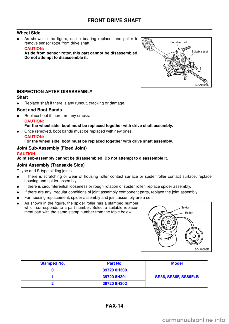
lAs shown in the figure, use a bearing replacer and puller to
remove sensor rotor from drive shaft.
CAUTION:
Aside from sensor rotor, this part cannot be disassembled.
Do not attempt to disassemble it.
INSPECTION AFTER DISASSEMBLY
Shaft
lReplace shaft if there is any runout, cracking or damage.
Boot and Boot Bands
lReplace boot if there are any cracks.
CAUTION:
For the wheel side, boot must be replaced together with drive shaft assembly.
lOnce removed, boot bands must be replaced with new ones.
CAUTION:
For the wheel side, boot must be replaced together with drive shaft assembly.
Joint Sub-Assembly (Fixed Joint)
CAUTION:
Joint sub-assembly cannot be disassembled. Do not attempt to disassemble it.
Joint Assembly (Transaxle Side)
T-typeandS-typeslidingjoints
lIf there is scratching or wear of housing roller contact surface or spider roller contact surface, replace
housing and spider assembly.
lIf there is circumferential looseness or rough rotation of spider roller, replace spider assembly.
lIf there are any irregular conditions of joint assembly component parts, replace the joint assembly.
lFor housing replacement, spider assembly and joint assembly are a set.
lAs shown in the figure, the spider roller has a stamped number
which corresponds to a part number. Select a suitable replace-
ment part with the same stamp number from the table below.
SDIA0595E
SDIA0596E
Stamped No. Part No. Model
0 39720 8H300
SS86, SS86F, SS86F+B 1 39720 8H301
2 39720 8H302
Page 2211 of 3066
FRONT DRIVE SHAFT
FAX-15
C
E
F
G
H
I
J
K
L
MA
B
FA X
Joint Assembly (Wheel Side)
CAUTION:
Joint assembly cannot be disassembled. Do not attempt to disassemble it.
ASSEMBLY
Transaxle Side
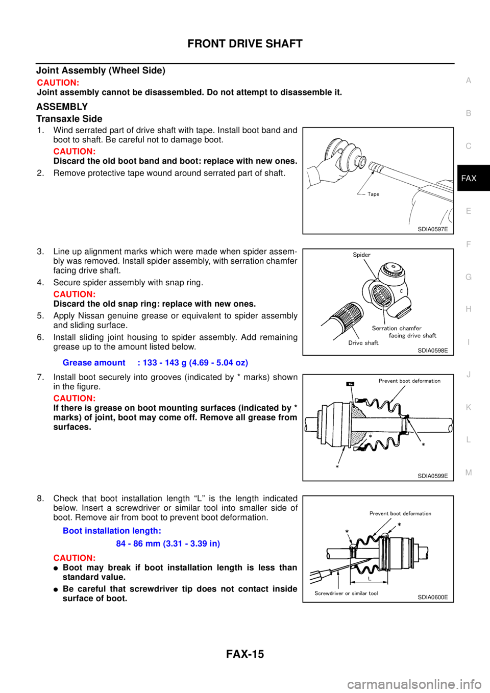
1. Wind serrated part of drive shaft with tape. Install boot band and
boot to shaft. Be careful not to damage boot.
CAUTION:
Discard the old boot band and boot: replace with new ones.
2. Remove protective tape wound around serrated part of shaft.
3. Line up alignment marks which were made when spider assem-
bly was removed. Install spider assembly, with serration chamfer
facing drive shaft.
4. Secure spider assembly with snap ring.
CAUTION:
Discard the old snap ring: replace with new ones.
5. Apply Nissan genuine grease or equivalent to spider assembly
and sliding surface.
6. Install sliding joint housing to spider assembly. Add remaining
grease up to the amount listed below.
7. Install boot securely into grooves (indicated by * marks) shown
in the figure.
CAUTION:
If there is grease on boot mounting surfaces (indicated by *
marks) of joint, boot may come off. Remove all grease from
surfaces.
8. Check that boot installation length “L” is the length indicated
below. Insert a screwdriver or similar tool into smaller side of
boot. Remove air from boot to prevent boot deformation.
CAUTION:
lBoot may break if boot installation length is less than
standard value.
lBe careful that screwdriver tip does not contact inside
surface of boot.
SDIA0597E
Grease amount : 133 - 143 g (4.69 - 5.04 oz)
SDIA0598E
SDIA0599E
Boot installation length:
84 - 86 mm (3.31 - 3.39 in)
SDIA0600E
Page 2212 of 3066
FAX-16
FRONT DRIVE SHAFT
9. Secure big and small ends of boot with new boot bands as
shown in figure.
CAUTION:
Rotate housing and check that boot installation position
does not change. If position changes, reinstall boot bands.
Wheel Side
1. Use a drift to press-fit sensor rotor into joint sub-assembly.
CAUTION:
lDiscard the old sensor rotor; replace with a new one.
lJoint assembly cannot be disassembled. Do not attempt
to disassemble it.
Dynamic Damper
lWhen dynamic damper has been removed, secure with bands
as shown in the figure so that measurements from fixed-joint
side are as listed below.
CAUTION:
Discard the old dynamic damper: replace with a new one.
Mounting Dimensions
SDIA0601E
SDIA0619E
FAC0156D
Drive shaft model Specification Dimension A Dimension B
ZF100SS86 Left
267 - 273 mm (10.51 - 10.75 in) 70 mm (2.76 in) ZF100SS86F
Right
ZF100SS86F+B
Page 2213 of 3066
SERVICE DATA AND SPECIFICATIONS (SDS)
FAX-17
C
E
F
G
H
I
J
K
L
MA
B
FA X
SERVICE DATA AND SPECIFICATIONS (SDS)PFP:00030
Wheel BearingEDS000IG
Drive ShaftEDS000IH
ZF100SS86, ZF100SS86F, ZF100SS86F+B
Wheel side ZF100 type joint assembly cannot be disassembly because a plastic boot and special boot band are used. Do not use other
drive shaft boots. If the boot or joint is damaged, replace the drive shaft assembly.
Dynamic DamperEDS0 00 II
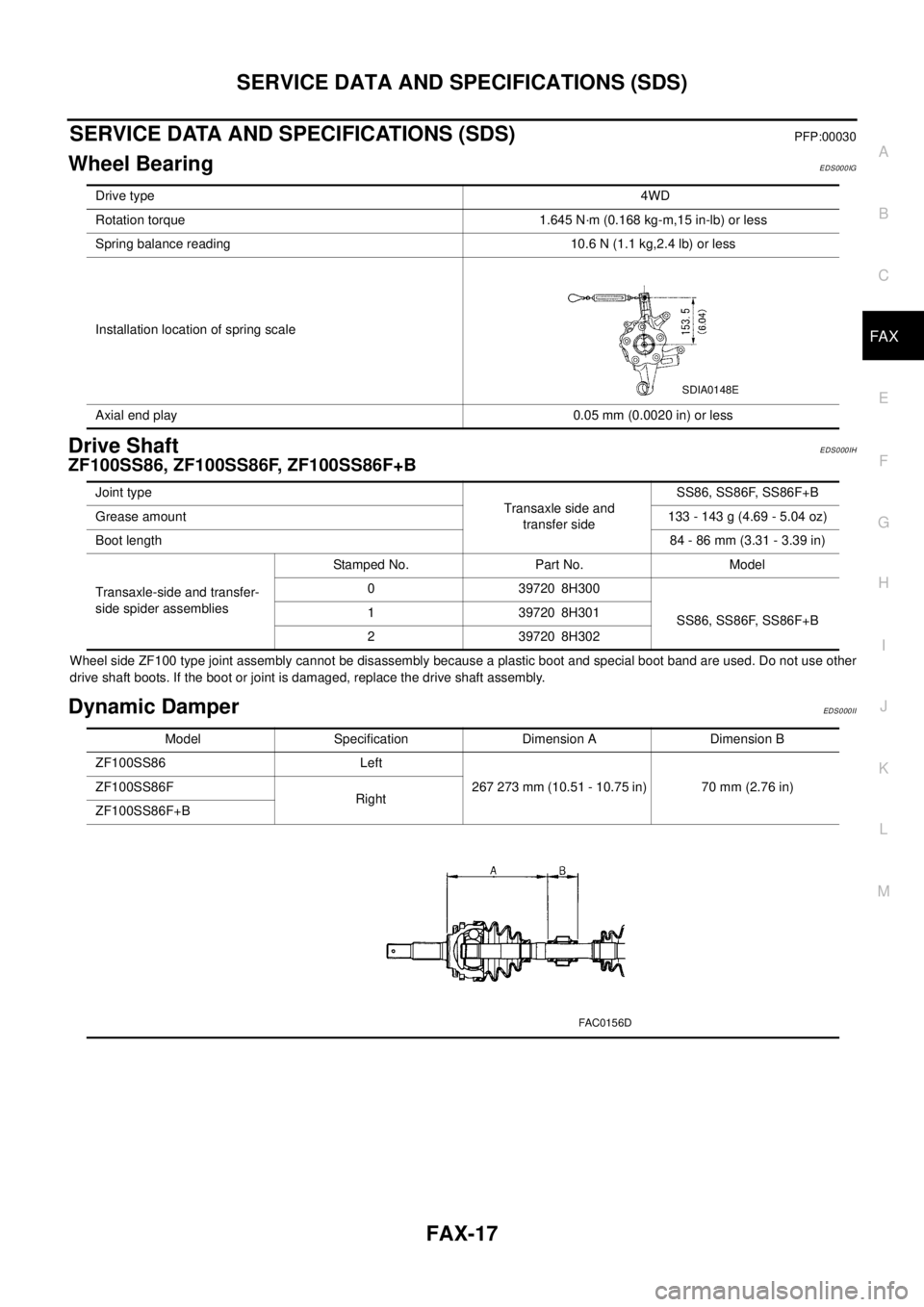
Drive type4WD
Rotation torque 1.645 N·m (0.168 kg-m,15 in-lb) or less
Spring balance reading 10.6 N (1.1 kg,2.4 lb) or less
Installation location of spring scale
Axial end play 0.05 mm (0.0020 in) or less
SDIA0148E
Joint type
Transaxle side and
transfer sideSS86, SS86F, SS86F+B
Grease amount133-143g(4.69-5.04oz)
Boot length84 - 86 mm (3.31 - 3.39 in)
Transaxle-side and transfer-
side spider assembliesStamped No. Part No. Model
0 39720 8H300
SS86, SS86F, SS86F+B 1 39720 8H301
2 39720 8H302
Model Specification Dimension A Dimension B
ZF100SS86 Left
267 273 mm (10.51 - 10.75 in) 70 mm (2.76 in) ZF100SS86F
Right
ZF100SS86F+B
FAC0156D
Page 2245 of 3066
FSU-6
FRONT SUSPENSION ASSEMBLY
On-Vehicle Inspection and Service
EES00072
LOOSENESS, BACKLASH AND DAMAGE OF MOUNTING PARTS AND CONNECTIONS
Lift vehicle and inspect the following:
lCheck mounting point of each component for looseness, backlash and damage.
lCheck lower ball joint end play.
1. Attach a dial gauge so that the contact rests on the brake caliper.
2. Set front wheels in a straight-ahead position. Do not depress brake pedal.
3. Measure axial endplay by placing an iron pry bar or something similar between transverse link and steer-
ing knuckle.
CAUTION:
Be careful not to damage ball joint boot.
4. If axial endplay is outside the standard, remove transverse link and check lower ball joint.
Wheel AlignmentEES00073
DESCRIPTION
lMeasure wheel alignment under unladen conditions. “Unladen conditions” means that fuel, coolant, and
lubricant are full. However, spare tire, jack, and hand tools should be unloaded.
PRELIMINARY INSPECTION
1. Check the tires for improper air pressure and wear.
2. Check road wheels for runout.
3. Check wheel bearing axial endplay.
4. Check lower ball joint axial endplay.
5. Check strut operation.
6. Check each mounting point of axle and suspension for looseness and deformation.
7. Check each link and arm for cracks, deformation, and other damage.
8. Check the vehicle posture.
INSPECTION OF CAMBER, CASTER, AND KINGPIN INCLINATION ANGLES
lCamber, caster, and kingpin inclination angles cannot be adjusted.
lBefore inspection, mount front wheels onto turning radius gauge. Mount rear wheels onto a stand that has
same height so the vehicle will remain horizontal.
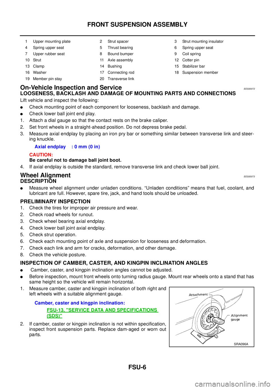
1. Measure camber, caster and kingpin inclination of both right and
left wheels with a suitable alignment gauge.
2. If camber, caster or kingpin inclination is not within specification,
inspect front suspension parts. Replace dam-aged or worn out
parts.
1 Upper mounting plate 2 Strut spacer 3 Strut mounting insulator
4 Spring upper seat 5 Thrust bearing 6 Spring upper seat
7 Upper rubber seat 8 Bound bumper 9 Coil spring
10 Strut 11 Axle assembly 12 Cotter pin
13 Clamp 14 Bushing 15 Stabilizer bar
16 Washer 17 Connecting rod 18 Suspension member
19 Member pin stay 20 Transverse link
Axial endplay : 0 mm (0 in)
Camber, caster and kingpin inclination:
FSU-13, "
SERVICE DATA AND SPECIFICATIONS
(SDS)"
SRA096A