2003 NISSAN X-TRAIL boot
[x] Cancel search: bootPage 2532 of 3066
MA-40
CHASSIS AND BODY MAINTENANCE
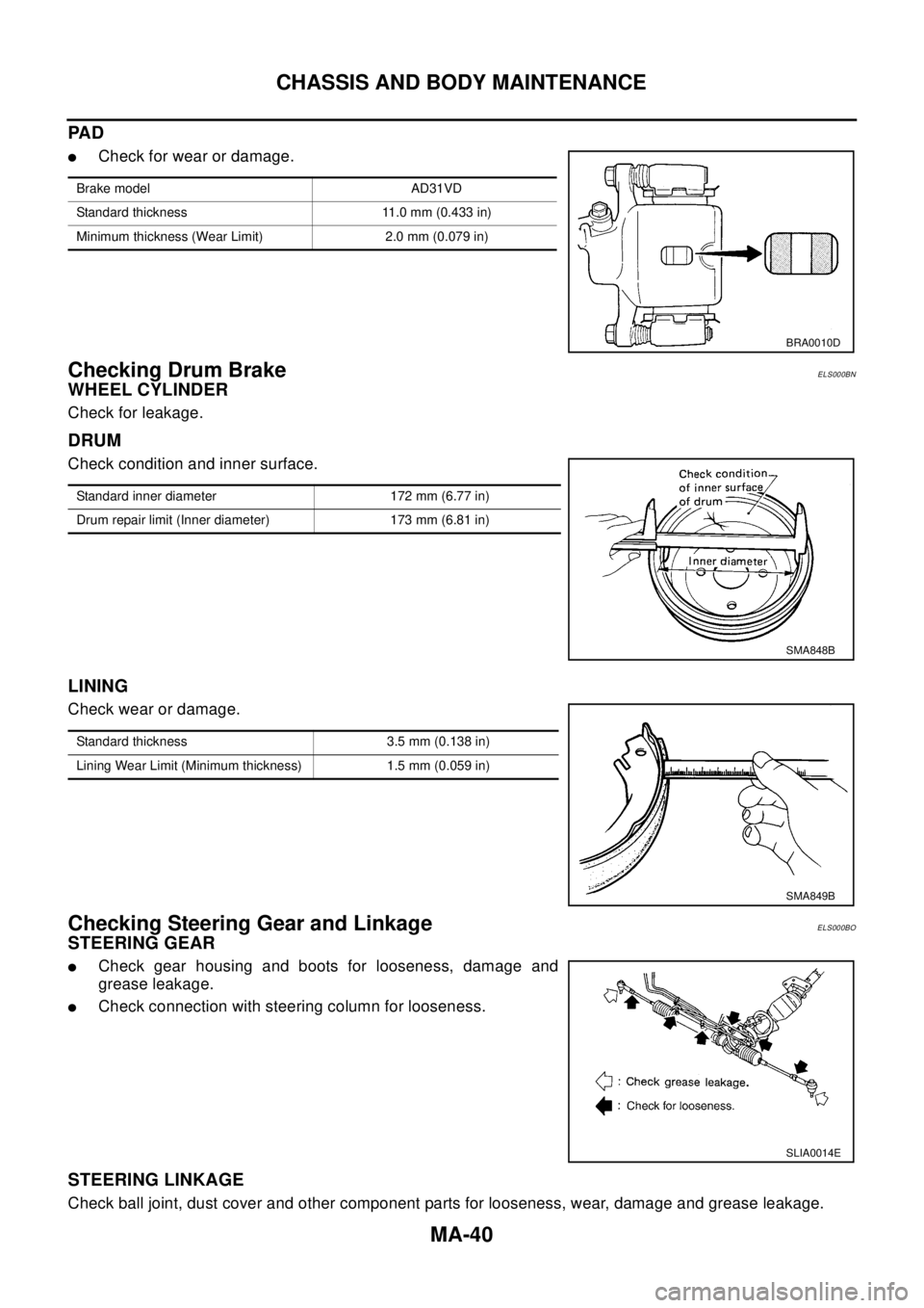
PA D
lCheck for wear or damage.
Checking Drum BrakeELS000BN
WHEEL CYLINDER
Check for leakage.
DRUM
Check condition and inner surface.
LINING
Check wear or damage.
Checking Steering Gear and LinkageELS000BO
STEERING GEAR
lCheck gear housing and boots for looseness, damage and
grease leakage.
lCheck connection with steering column for looseness.
STEERING LINKAGE
Check ball joint, dust cover and other component parts for looseness, wear, damage and grease leakage.
Brake model AD31VD
Standard thickness 11.0 mm (0.433 in)
Minimum thickness (Wear Limit) 2.0 mm (0.079 in)
BRA0010D
Standard inner diameter 172 mm (6.77 in)
Drum repair limit (Inner diameter) 173 mm (6.81 in)
SMA848B
Standard thickness 3.5 mm (0.138 in)
Lining Wear Limit (Minimum thickness) 1.5 mm (0.059 in)
SMA849B
SLIA0014E
Page 2533 of 3066
CHASSIS AND BODY MAINTENANCE
MA-41
C
D
E
F
G
H
I
J
K
MA
B
MA
Checking Power Steering Fluid and LinesELS000BP
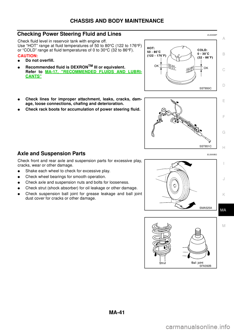
Check fluid level in reservoir tank with engine off.
Use “HOT” range at fluid temperatures of 50 to 80°C (122 to 176°F)
or “COLD” range at fluid temperatures of 0 to 30°C(32to86°F).
CAUTION:
lDo not overfill.
lRecommended fluid is DEXRONTMIII or equivalent.
Refer toMA-17, "
RECOMMENDED FLUIDS AND LUBRI-
CANTS"
lCheck lines for improper attachment, leaks, cracks, dam-
age, loose connections, chafing and deterioration.
lCheck rack boots for accumulation of power steering fluid.
Axle and Suspension PartsELS000BQ
Check front and rear axle and suspension parts for excessive play,
cracks, wear or other damage.
lShake each wheel to check for excessive play.
lCheck wheel bearings for smooth operation.
lCheck axle and suspension nuts and bolts for looseness.
lCheck strut (shock absorber) for oil leakage or other damage.
lCheck suspension ball joint for grease leakage and ball joint
dust cover for cracks or other damage.
SST850C
SST851C
SMA525A
SFA392B
Page 2534 of 3066
MA-42
CHASSIS AND BODY MAINTENANCE
Drive Shaft
ELS000CL
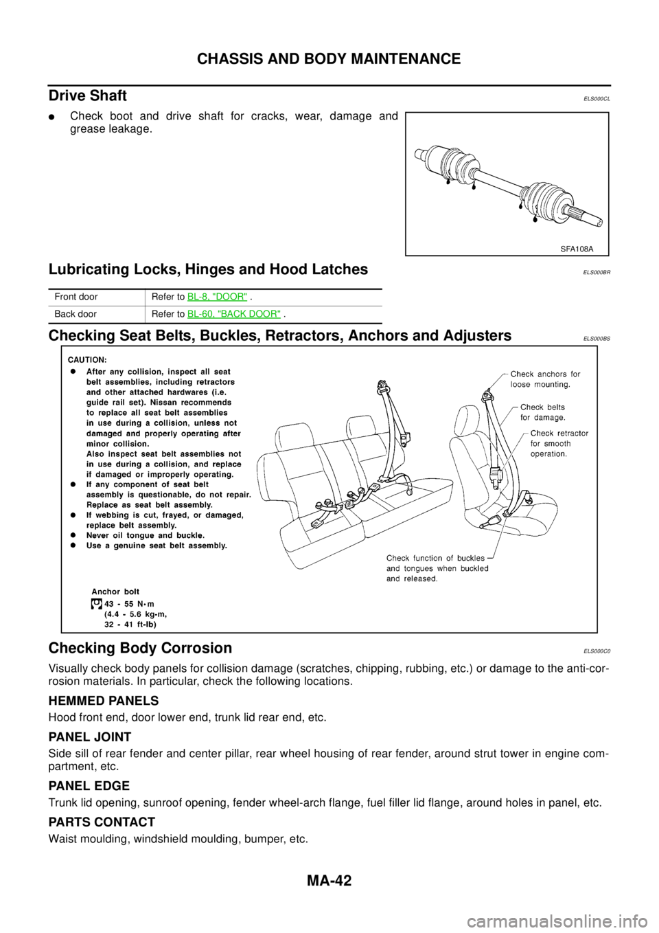
lCheck boot and drive shaft for cracks, wear, damage and
grease leakage.
Lubricating Locks, Hinges and Hood LatchesELS000BR
Checking Seat Belts, Buckles, Retractors, Anchors and AdjustersELS000BS
Checking Body CorrosionELS000C0
Visually check body panels for collision damage (scratches, chipping, rubbing, etc.) or damage to the anti-cor-
rosion materials. In particular, check the following locations.
HEMMED PANELS
Hood front end, door lower end, trunk lid rear end, etc.
PANEL JOINT
Side sill of rear fender and center pillar, rear wheel housing of rear fender, around strut tower in engine com-
partment, etc.
PANEL EDGE
Trunk lid opening, sunroof opening, fender wheel-arch flange, fuel filler lid flange, around holes in panel, etc.
PA R T S C O N TA C T
Waist moulding, windshield moulding, bumper, etc.
SFA108A
Front door Refer toBL-8, "DOOR".
Back door Refer toBL-60, "
BACK DOOR".
Page 2757 of 3066
REAR PROPELLER SHAFT
PR-3
C
E
F
G
H
I
J
K
L
MA
B
PR
Removal and InstallationEDS00052
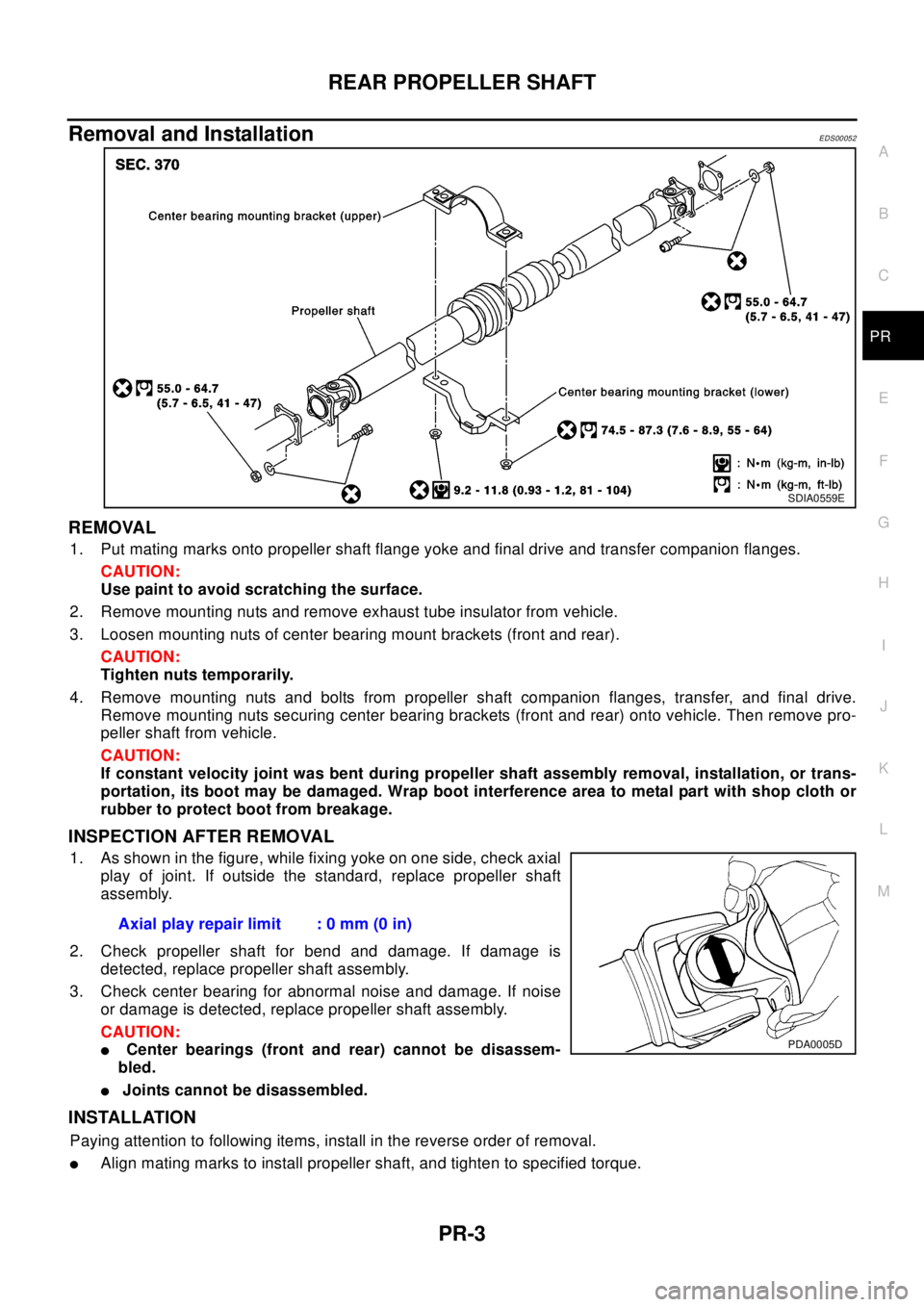
REMOVAL
1. Put mating marks onto propeller shaft flange yoke and final drive and transfer companion flanges.
CAUTION:
Use paint to avoid scratching the surface.
2. Remove mounting nuts and remove exhaust tube insulator from vehicle.
3. Loosen mounting nuts of center bearing mount brackets (front and rear).
CAUTION:
Tighten nuts temporarily.
4. Remove mounting nuts and bolts from propeller shaft companion flanges, transfer, and final drive.
Remove mounting nuts securing center bearing brackets (front and rear) onto vehicle. Then remove pro-
peller shaft from vehicle.
CAUTION:
If constant velocity joint was bent during propeller shaft assembly removal, installation, or trans-
portation, its boot may be damaged. Wrap boot interference area to metal part with shop cloth or
rubber to protect boot from breakage.
INSPECTION AFTER REMOVAL
1. As shown in the figure, while fixing yoke on one side, check axial
play of joint. If outside the standard, replace propeller shaft
assembly.
2. Check propeller shaft for bend and damage. If damage is
detected, replace propeller shaft assembly.
3. Check center bearing for abnormal noise and damage. If noise
or damage is detected, replace propeller shaft assembly.
CAUTION:
lCenter bearings (front and rear) cannot be disassem-
bled.
lJoints cannot be disassembled.
INSTALLATION
Paying attention to following items, install in the reverse order of removal.
lAlign mating marks to install propeller shaft, and tighten to specified torque.
SDIA0559E
Axial play repair limit : 0 mm (0 in)
PDA0005D
Page 2772 of 3066
PS-12
POWER STEERING GEAR AND LINKAGE
POWER STEERING GEAR AND LINKAGE
PFP:49001
Removal and InstallationEGS0004I
REMOVAL
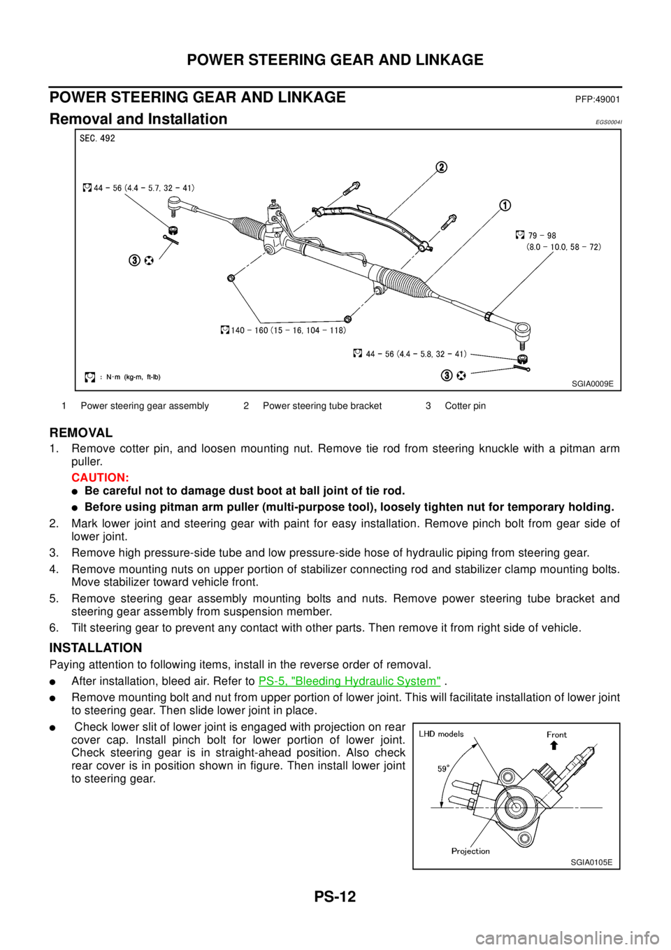
1. Remove cotter pin, and loosen mounting nut. Remove tie rod from steering knuckle with a pitman arm
puller.
CAUTION:
lBe careful not to damage dust boot at ball joint of tie rod.
lBefore using pitman arm puller (multi-purpose tool), loosely tighten nut for temporary holding.
2. Mark lower joint and steering gear with paint for easy installation. Remove pinch bolt from gear side of
lower joint.
3. Remove high pressure-side tube and low pressure-side hose of hydraulic piping from steering gear.
4. Remove mounting nuts on upper portion of stabilizer connecting rod and stabilizer clamp mounting bolts.
Move stabilizer toward vehicle front.
5. Remove steering gear assembly mounting bolts and nuts. Remove power steering tube bracket and
steering gear assembly from suspension member.
6. Tilt steering gear to prevent any contact with other parts. Then remove it from right side of vehicle.
INSTALLATION
Paying attention to following items, install in the reverse order of removal.
lAfter installation, bleed air. Refer toPS-5, "Bleeding Hydraulic System".
lRemove mounting bolt and nut from upper portion of lower joint. This will facilitate installation of lower joint
to steering gear. Then slide lower joint in place.
lCheck lower slit of lower joint is engaged with projection on rear
cover cap. Install pinch bolt for lower portion of lower joint.
Check steering gear is in straight-ahead position. Also check
rear cover is in position shown in figure. Then install lower joint
to steering gear.
SGIA0009E
1 Power steering gear assembly 2 Power steering tube bracket 3 Cotter pin
SGIA0105E
Page 2775 of 3066
POWER STEERING GEAR AND LINKAGE
PS-15
C
D
E
F
H
I
J
K
L
MA
B
PS
Disassembly and AssemblyEGS0004K
DISASSEMBLY
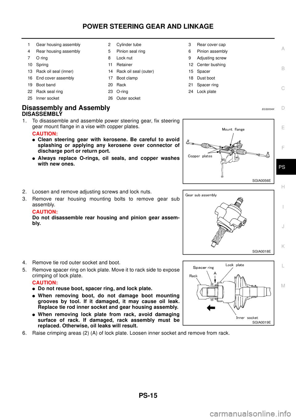
1. To disassemble and assemble power steering gear, fix steering
gear mount flange in a vise with copper plates.
CAUTION:
lClean steering gear with kerosene. Be careful to avoid
splashing or applying any kerosene over connector of
discharge port or return port.
lAlways replace O-rings, oil seals, and copper washes
with new ones.
2. Loosen and remove adjusting screws and lock nuts.
3. Remove rear housing mounting bolts to remove gear sub
assembly.
CAUTION:
Do not disassemble rear housing and pinion gear assem-
bly.
4. Remove tie rod outer socket and boot.
5. Remove spacer ring on lock plate. Move it to rack side to expose
crimping of lock plate.
CAUTION:
lDo not reuse boot, spacer ring, and lock plate.
lWhen removing boot, do not damage boot mounting
grooves by tool. If it damaged, it may cause oil leak.
Replace tie rod inner socket and gear housing assembly.
lWhen removing lock plate from rack, avoid damaging
surface of rack. If damaged, rack assembly must be
replaced. Otherwise, oil leaks will result.
6. Raise crimping areas (2) (A) of lock plate. Loosen inner socket and remove from rack.
1 Gear housing assembly 2 Cylinder tube 3 Rear cover cap
4 Rear housing assembly 5 Pinion seal ring 6 Pinion assembly
7 O ring 8 Lock nut 9 Adjusting screw
10 Spring 11 Retainer 12 Center bushing
13 Rack oil seal (inner) 14 Rack oil seal (outer) 15 Spacer
16 End cover assembly 17 Boot clamp 18 Dust boot
19 Boot band 20 Rack 21 Spacer ring
22 Rack seal ring 23 O-ring 24 Lock plate
25 Inner socket 26 Outer socket
SGIA0056E
SGIA0018E
SGIA0019E
Page 2776 of 3066
PS-16
POWER STEERING GEAR AND LINKAGE
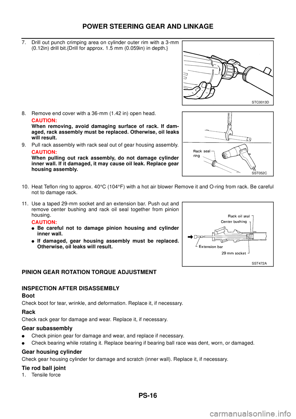
7. Drill out punch crimping area on cylinder outer rim with a 3-mm
(0.12in) drill bit.{Drill for approx. 1.5 mm (0.059in) in depth.}
8. Remove end cover with a 36-mm (1.42 in) open head.
CAUTION:
When removing, avoid damaging surface of rack. If dam-
aged, rack assembly must be replaced. Otherwise, oil leaks
will result.
9. Pull rack assembly with rack seal out of gear housing assembly.
CAUTION:
When pulling out rack assembly, do not damage cylinder
inner wall. If it damaged, it may cause oil leak. Replace gear
housing assembly.
10. Heat Teflon ring to approx. 40°C (104°F) with a hot air blower Remove it and O-ring from rack. Be careful
not to damage rack.
11. Use a taped 29-mm socket and an extension bar. Push out and
remove center bushing and rack oil seal together from pinion
housing.
CAUTION:
lBe careful not to damage pinion housing and cylinder
inner wall.
lIf damaged, gear housing assembly must be replaced.
Otherwise, oil leaks will result.
PINION GEAR ROTATION TORQUE ADJUSTMENT
INSPECTION AFTER DISASSEMBLY
Boot
Check boot for tear, wrinkle, and deformation. Replace it, if necessary.
Rack
Check rack gear for damage and wear. Replace it, if necessary.
Gear subassembly
lCheck pinion gear for damage and wear, and replace if necessary.
lCheck bearing while rotating it. Replace bearing if bearing ball race was dent, worn, or damaged.
Gear housing cylinder
Check gear housing cylinder for damage and scratch (inner wall). Replace it, if necessary.
Tie rod ball joint
1. Tensile force
STC0013D
SST052C
SST472A
Page 2781 of 3066
POWER STEERING GEAR AND LINKAGE
PS-21
C
D
E
F
H
I
J
K
L
MA
B
PS
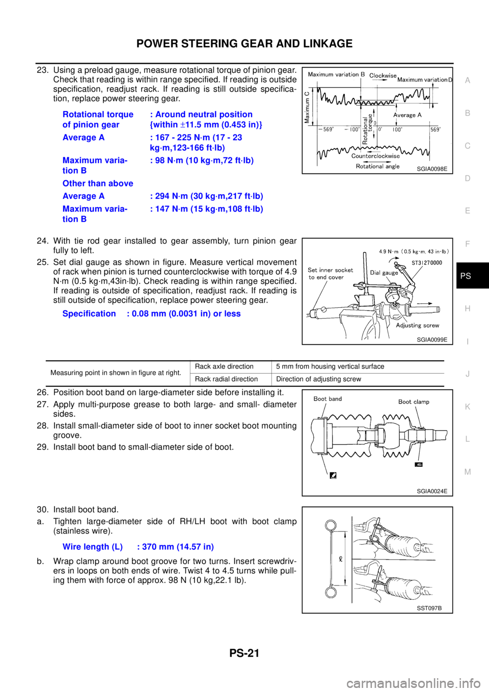
23. Using a preload gauge, measure rotational torque of pinion gear.
Check that reading is within range specified. If reading is outside
specification, readjust rack. If reading is still outside specifica-
tion, replace power steering gear.
24. With tie rod gear installed to gear assembly, turn pinion gear
fully to left.
25. Set dial gauge as shown in figure. Measure vertical movement
of rack when pinion is turned counterclockwise with torque of 4.9
N·m (0.5 kg·m,43in·lb). Check reading is within range specified.
If reading is outside of specification, readjust rack. If reading is
still outside of specification, replace power steering gear.
26. Position boot band on large-diameter side before installing it.
27. Apply multi-purpose grease to both large- and small- diameter
sides.
28. Install small-diameter side of boot to inner socket boot mounting
groove.
29. Install boot band to small-diameter side of boot.
30. Install boot band.
a. Tighten large-diameter side of RH/LH boot with boot clamp
(stainless wire).
b. Wrap clamp around boot groove for two turns. Insert screwdriv-
ers in loops on both ends of wire. Twist 4 to 4.5 turns while pull-
ing them with force of approx. 98 N (10 kg,22.1 lb).Rotational torque
of pinion gear: Around neutral position
{within±11.5 mm (0.453 in)}
Average A : 167 - 225 N·m (17 - 23
kg·m,123-166 ft·lb)
Maximum varia-
tion B: 98 N·m (10 kg·m,72 ft·lb)
Other than above
Average A : 294 N·m (30 kg·m,217 ft·lb)
Maximum varia-
tion B: 147 N·m (15 kg·m,108 ft·lb)
SGIA0098E
Specification : 0.08 mm (0.0031 in) or less
SGIA0099E
Measuring point in shown in figure at right.Rack axle direction 5 mm from housing vertical surface
Rack radial direction Direction of adjusting screw
SGIA0024E
Wire length (L) : 370 mm (14.57 in)
SST097B