2003 NISSAN X-TRAIL air bleeding
[x] Cancel search: air bleedingPage 993 of 3066

CL-1
CLUTCH
C TRANSMISSION/TRANSAXLE
CONTENTS
D
E
F
G
H
I
J
K
L
M
SECTION
A
B
CL
CLUTCH
PRECAUTIONS .......................................................... 2
Caution ..................................................................... 2
PREPARATION ........................................................... 3
Special Service Tools ............................................... 3
Commercial Service Tool ......................................... 3
NOISE, VIBRATION, AND HARSHNESS (NVH)
TROUBLESHOOTING ................................................ 4
NVH Troubleshooting Chart ..................................... 4
CLUTCH PEDAL ........................................................ 5
On-vehicle Inspection and Adjustment ..................... 5
HEIGHT ADJUSTMENT ....................................... 5
CLUTCH SWITCH POSITION ADJUSTMENT ..... 5
FREE PLAY INSPECTION .................................... 6
CLEARANCE CHECK ........................................... 6
Removal and Installation .......................................... 6
INSPECTION AFTER REMOVAL ......................... 7
CLUTCH FLUID .......................................................... 8
Air Bleeding Procedure ............................................ 8
CLUTCH MASTER CYLINDER .................................. 9
Removal and Installation .......................................... 9
REMOVAL ............................................................. 9
INSTALLATION ..................................................... 9
Disassembly and Assembly ................................... 10
DISASSEMBLY ................................................... 10
INSPECTION AFTER DISASSEMBLY ............... 10
ASSEMBLY ......................................................... 10
OPERATING CYLINDER ...........................................11Removal and Installation ........................................ 11
REMOVAL ........................................................... 11
INSTALLATION ................................................... 11
Disassembly and Assembly .................................... 11
DISASSEMBLY ................................................... 11
INSPECTION AFTER DISASSEMBLY ................ 11
ASSEMBLY ......................................................... 11
CLUTCH PIPING ....................................................... 12
Removal and Installation ........................................ 12
CLUTCH RELEASE MECHANISM ........................... 13
Removal and Installation ........................................ 13
REMOVAL ........................................................... 13
INSPECTION AFTER REMOVEL ....................... 13
INSTALLATION ................................................... 13
CLUTCH DISC, CLUTCH COVER AND FLYWHEEL... 15
Removal and Installation ........................................ 15
REMOBAL ........................................................... 15
INSPECTION AND ADJUSTMENT AFTER
REMOVAL ........................................................... 15
INSTALLATION ................................................... 16
SERVICE DATA AND SPECIFICATIONS (SDS) ...... 17
Clutch Control System ............................................ 17
Clutch Master Cylinder ........................................... 17
Clutch Operating Cylinder ...................................... 17
Clutch Disk ............................................................. 17
Clutch Cover ........................................................... 17
Clutch Pedal ........................................................... 17
Page 1000 of 3066
CL-8
CLUTCH FLUID
CLUTCH FLUID
PFP:00017
Air Bleeding ProcedureECS001WD
CAUTION:
lMonitor fluid level in the reservoir to make sure it does not empty.
lDo not spill clutch fluid onto painted surfaces. If it spills, wipe up immediately and wash the
affected area with water.
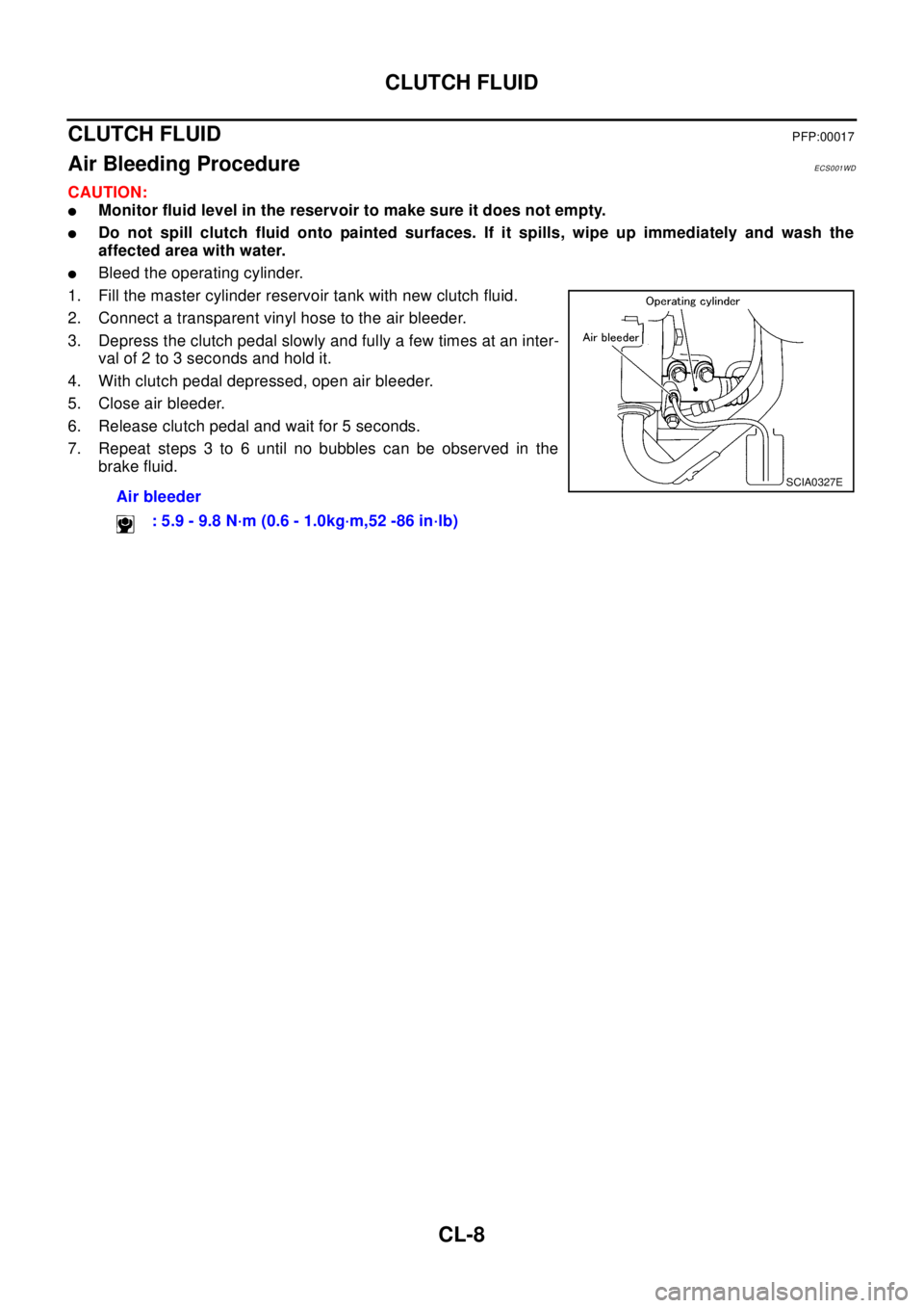
lBleed the operating cylinder.
1. Fill the master cylinder reservoir tank with new clutch fluid.
2. Connect a transparent vinyl hose to the air bleeder.
3. Depress the clutch pedal slowly and fully a few times at an inter-
val of 2 to 3 seconds and hold it.
4. With clutch pedal depressed, open air bleeder.
5. Close air bleeder.
6. Release clutch pedal and wait for 5 seconds.
7. Repeat steps 3 to 6 until no bubbles can be observed in the
brake fluid.
Air bleeder
: 5.9 - 9.8 N·m (0.6 - 1.0kg·m,52 -86 in·lb)
SCIA0327E
Page 1001 of 3066
CLUTCH MASTER CYLINDER
CL-9
D
E
F
G
H
I
J
K
L
MA
B
CL
CLUTCH MASTER CYLINDERPFP:30610
Removal and InstallationECS00353
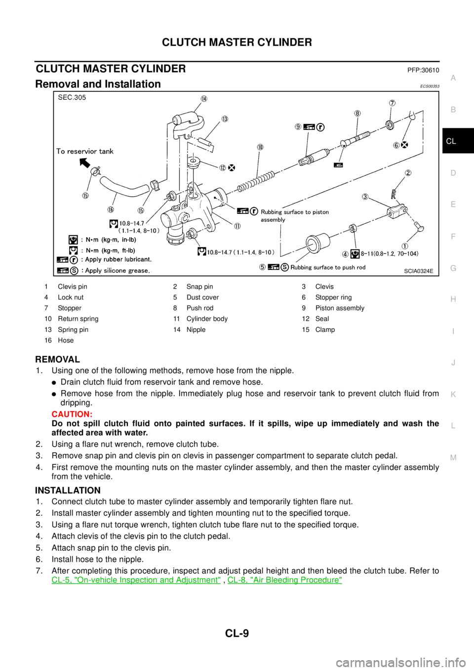
REMOVAL
1. Using one of the following methods, remove hose from the nipple.
lDrain clutch fluid from reservoir tank and remove hose.
lRemove hose from the nipple. Immediately plug hose and reservoir tank to prevent clutch fluid from
dripping.
CAUTION:
Do not spill clutch fluid onto painted surfaces. If it spills, wipe up immediately and wash the
affected area with water.
2. Using a flare nut wrench, remove clutch tube.
3. Remove snap pin and clevis pin on clevis in passenger compartment to separate clutch pedal.
4. First remove the mounting nuts on the master cylinder assembly, and then the master cylinder assembly
from the vehicle.
INSTALLATION
1. Connect clutch tube to master cylinder assembly and temporarily tighten flare nut.
2. Install master cylinder assembly and tighten mounting nut to the specified torque.
3. Using a flare nut torque wrench, tighten clutch tube flare nut to the specified torque.
4. Attach clevis of the clevis pin to the clutch pedal.
5. Attach snap pin to the clevis pin.
6. Install hose to the nipple.
7. After completing this procedure, inspect and adjust pedal height and then bleed the clutch tube. Refer to
CL-5, "
On-vehicle Inspection and Adjustment",CL-8, "Air Bleeding Procedure"
SCIA0324E
1 Clevis pin 2 Snap pin 3 Clevis
4 Lock nut 5 Dust cover 6 Stopper ring
7 Stopper 8 Push rod 9 Piston assembly
10 Return spring 11 Cylinder body 12 Seal
13 Spring pin 14 Nipple 15 Clamp
16 Hose
Page 1003 of 3066
OPERATING CYLINDER
CL-11
D
E
F
G
H
I
J
K
L
MA
B
CL
OPERATING CYLINDERPFP:30620
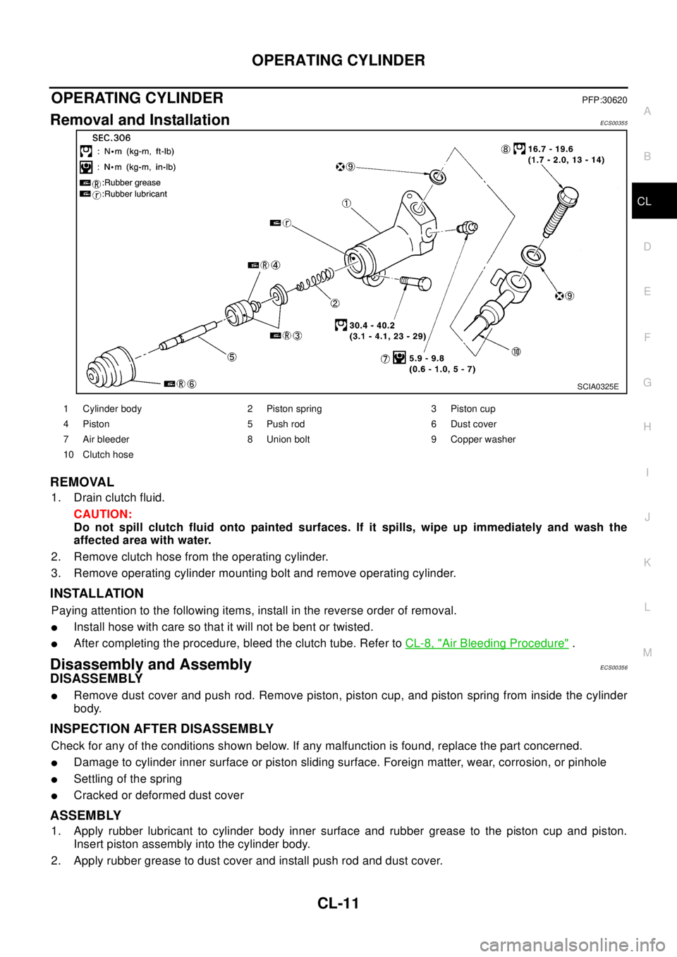
Removal and InstallationECS00355
REMOVAL
1. Drainclutchfluid.
CAUTION:
Do not spill clutch fluid onto painted surfaces. If it spills, wipe up immediately and wash the
affected area with water.
2. Remove clutch hose from the operating cylinder.
3. Remove operating cylinder mounting bolt and remove operating cylinder.
INSTALLATION
Paying attention to the following items, install in the reverse order of removal.
lInstall hose with care so that it will not be bent or twisted.
lAfter completing the procedure, bleed the clutch tube. Refer toCL-8, "Air Bleeding Procedure".
Disassembly and AssemblyECS00356
DISASSEMBLY
lRemove dust cover and push rod. Remove piston, piston cup, and piston spring from inside the cylinder
body.
INSPECTION AFTER DISASSEMBLY
Check for any of the conditions shown below. If any malfunction is found, replace the part concerned.
lDamage to cylinder inner surface or piston sliding surface. Foreign matter, wear, corrosion, or pinhole
lSettling of the spring
lCracked or deformed dust cover
ASSEMBLY
1. Apply rubber lubricant to cylinder body inner surface and rubber grease to the piston cup and piston.
Insert piston assembly into the cylinder body.
2. Apply rubber grease to dust cover and install push rod and dust cover.
SCIA0325E
1 Cylinder body 2 Piston spring 3 Piston cup
4 Piston 5 Push rod 6 Dust cover
7 Air bleeder 8 Union bolt 9 Copper washer
10 Clutch hose
Page 1004 of 3066
CL-12
CLUTCH PIPING
CLUTCH PIPING
PFP:30650
Removal and InstallationECS0 01 W I
Carefully observe the following steps during clutch tube removal and installation.
lDo not spill clutch fluid onto painted surfaces. If it spills, wipe up immediately and wash the affected area
with water.
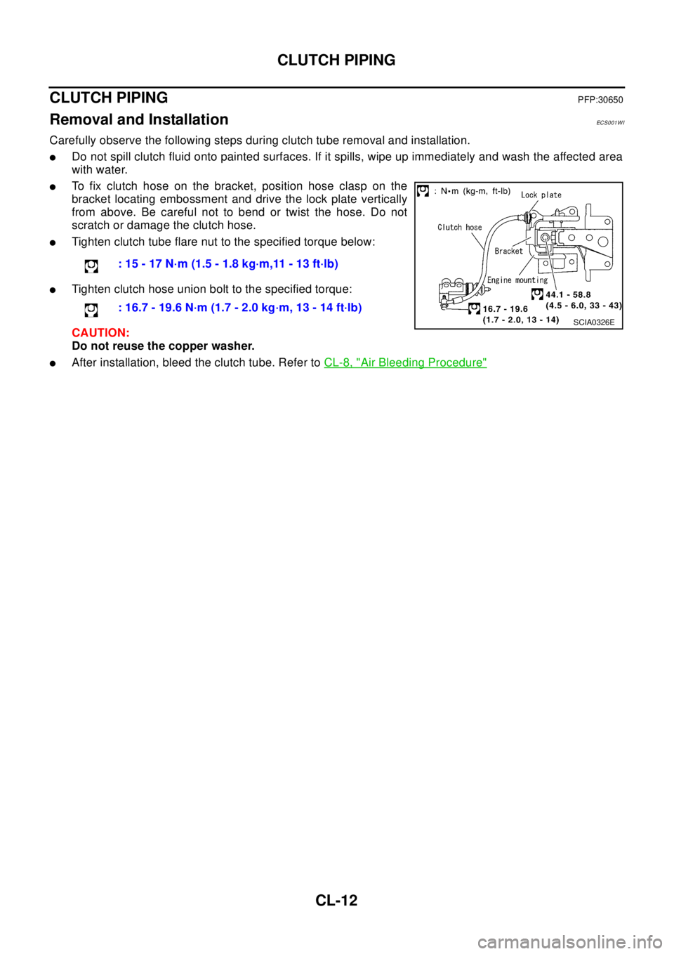
lTo fix clutch hose on the bracket, position hose clasp on the
bracket locating embossment and drive the lock plate vertically
from above. Be careful not to bend or twist the hose. Do not
scratch or damage the clutch hose.
lTighten clutch tube flare nut to the specified torque below:
lTighten clutch hose union bolt to the specified torque:
CAUTION:
Do not reuse the copper washer.
lAfter installation, bleed the clutch tube. Refer toCL-8, "Air Bleeding Procedure"
:15-17N·m(1.5-1.8kg·m,11-13ft·lb)
: 16.7 - 19.6 N·m (1.7 - 2.0 kg·m, 13 - 14 ft·lb)
SCIA0326E
Page 1041 of 3066
![NISSAN X-TRAIL 2003 Electronic Repair Manual ENGINE COOLANT
CO-31
[YD22DDTi]
C
D
E
F
G
H
I
J
K
L
MA
CO
3. Open drain plugs on cylinder block and air relief plug.
4. Check drained coolant for contaminants such as rust, corrosion
or discoloration.](/manual-img/5/57402/w960_57402-1040.png "NISSAN X-TRAIL 2003 Electronic Repair Manual ENGINE COOLANT
CO-31
[YD22DDTi]
C
D
E
F
G
H
I
J
K
L
MA
CO
3. Open drain plugs on cylinder block and air relief plug.
4. Check drained coolant for contaminants such as rust, corrosion
or discoloration.")
ENGINE COOLANT
CO-31
[YD22DDTi]
C
D
E
F
G
H
I
J
K
L
MA
CO
3. Open drain plugs on cylinder block and air relief plug.
4. Check drained coolant for contaminants such as rust, corrosion
or discoloration.
If contaminated, flush engine cooling system. Refer toCO-32,
"FLUSHING COOLING SYSTEM".
REFILLING ENGINE COOLANT
1. Install reservoir tank, radiator drain plug and cylinder block drain plug.
Apply sealant to the thread of cylinder block drain plug.
lUse Genuine Liquid Gasket or equivalent.
2. Fill radiator slowly with coolant until coolant spills from the air
relief plugs, then install air relief plugs.
CAUTION:
If the filling rate is too fast, this could lead to air being
mixed in the coolant. Be sure to fill the coolant slowly
according to the rate indicated above.
lReplace the copper washer of the air bleeding plug.
lUse genuine Nissan anti-freeze coolant or equivalent mixed with water (distilled or demineralized).
Refer toMA-17, "
RECOMMENDED FLUIDS AND LUBRICANTS".
lPour coolant through coolant filler neck slowly of less than 2 (1-3/4 lmp qt) a minute to allow air
in system to escape.
SBIA0129E
SBIA0130E
: 7.8 - 11.8 N·m (0.8 -1.2 kg-m , 69 - 104 in-lb)
Air relief plug :
: 6.7 - 7.9 N·m (0.68 - 0.81 kg-m, 59 - 70 in-lb)
Engine coolant capacity (With reservoir tank):
9.5 ( 8-3/8 Imp qt)
SMA182B
Reservoir tank : 0.6 (1/2 lmp qt )
Page 1778 of 3066
![NISSAN X-TRAIL 2003 Electronic Repair Manual EC-664
[YD]
BASIC SERVICE PROCEDURE
BASIC SERVICE PROCEDURE
PFP:00018
Fuel FilterEBS0036N
DESCRIPTION
A water draining cock is on the lower side and a priming pump for bleeding air is on the upper sid](/manual-img/5/57402/w960_57402-1777.png "NISSAN X-TRAIL 2003 Electronic Repair Manual EC-664
[YD]
BASIC SERVICE PROCEDURE
BASIC SERVICE PROCEDURE
PFP:00018
Fuel FilterEBS0036N
DESCRIPTION
A water draining cock is on the lower side and a priming pump for bleeding air is on the upper sid")
EC-664
[YD]
BASIC SERVICE PROCEDURE
BASIC SERVICE PROCEDURE
PFP:00018
Fuel FilterEBS0036N
DESCRIPTION
A water draining cock is on the lower side and a priming pump for bleeding air is on the upper side.
AIR BLEEDING
Pump the priming pump to bleed air.
lWhen air is bled completely, the pumping of the priming pump
suddenly becomes heavy. Stop the operation at that time.
lIf it is difficult to bleed air by the pumping of the priming pump
(the pumping of the priming pump does not become heavy), dis-
connect the fuel supply hose between the fuel filter and the fuel
gallery. Then, perform the operation described above, and make
sure that fuel comes out. (Use a pan, etc. so as not to spill fuel.
Do not let fuel get on engine and other parts.) After that, connect
the hose, then bleed air again.
lStart engine and let it idle for at least one minute after perform-
ing air bleeding.
WATER DRAINING
1. Remove the fuel filter, filter bracket, protector assembly from the dash panel as follows.
a. Remove the air cleaner case (upper), air duct assembly, and vacuum hose for brake booster (between the
vacuum pump and vacuum pipe).
CAUTION:
After the duct is removed, cover the opening with gum tape, etc. to prevent foreign object from
getting into the engine during the operation.
b. Remove the mounting nuts on the dash panel, then remove the fuel filter, filter bracket, and protector
assembly from the dash panel.
lIt is not necessary to disconnect the fuel hose.
2. Using a tool such as a pliers, loosen the water draining cock at the bottom of the fuel filter.
Accelerator Pedal Released Position LearningEBS009NW
DESCRIPTION
"Accelerator Pedal Released Position Learning" is an operating to learn the fully released position of the
accelerator pedal by monitoring the accelerator pedal position sensor output signal. It must be performed
when accelerator work unit or ECM is replaced.
OPERATION PROCEDURE
1. Turn ignition switch "ON".
2. Select "OFF ACCEL PO SIG" in "ACTIVE TEST" mode with
CONSULT-II
3. Make sure that accelerator pedal is released.
SEF375Y
PBIB0411E
Page 1788 of 3066
![NISSAN X-TRAIL 2003 Electronic Repair Manual EC-674
[YD]
TROUBLE DIAGNOSIS
5.BLEED AIR FROM FUEL SYSTEM
1. Stop engine.
2. Use priming pump to bleed air from fuel system. Refer toEC-664, "
AIR BLEEDING".
>> GO TO 6.
6.CHECK IDLE SPEED AGAIN
With](/manual-img/5/57402/w960_57402-1787.png "NISSAN X-TRAIL 2003 Electronic Repair Manual EC-674
[YD]
TROUBLE DIAGNOSIS
5.BLEED AIR FROM FUEL SYSTEM
1. Stop engine.
2. Use priming pump to bleed air from fuel system. Refer toEC-664, \"
AIR BLEEDING\".
>> GO TO 6.
6.CHECK IDLE SPEED AGAIN
With")
EC-674
[YD]
TROUBLE DIAGNOSIS
5.BLEED AIR FROM FUEL SYSTEM
1. Stop engine.
2. Use priming pump to bleed air from fuel system. Refer toEC-664, "
AIR BLEEDING".
>> GO TO 6.
6.CHECK IDLE SPEED AGAIN
With CONSULT-II
1. Start engine and let it idle.
2. Select “CKPS·RPM (TDC)” in “DATA MONITOR” mode with CONSULT-II.
3. Read idle speed.
OK or NG
OK >>INSPECTION END
NG >> GO TO 7.
7.DRAIN WATER FROM FUEL FILTER
Drain water from fuel filter. Refer toEC-664, "
WATER DRAINING".
>> GO TO 8.
8.CHECK IDLE SPEED AGAIN
With CONSULT-II
1. Start engine and let it idle.
2. Select “CKPS·RPM (TDC)” in “DATA MONITOR” mode with CONSULT-II.
3. Read idle speed.
OK or NG
OK >>INSPECTION END
NG >> GO TO 9.
9.CHECK AIR CLEANER FILTER
Check air cleaner filter for clogging or breaks.
OK or NG
OK >> GO TO 10.
NG >> Replace air cleaner filter.725±25 rpm
SEF817Y
725±25 rpm
SEF817Y