Page 270 of 3502
AT-262
DISASSEMBLY
d. Remove thrust washer and bearing race from oil pump assem-
bly.
35. Remove brake band according to the following procedures.
a. Loosen lock nut, and then remove anchor end pin and lock nut
as a set from transaxle case.
b. Remove brake band and strut from transaxle case.
�To prevent brake linings from cracking or peeling, do not
stretch the flexible band unnecessarily. When removing
brake band, always secure it with a clip as shown in the
figure.
Leave the clip in position after removing brake band.
SCIA3629E
SCIA4869E
SAT196F
SAT039D
Page 271 of 3502
DISASSEMBLY
AT-263
D
E
F
G
H
I
J
K
L
MA
B
AT
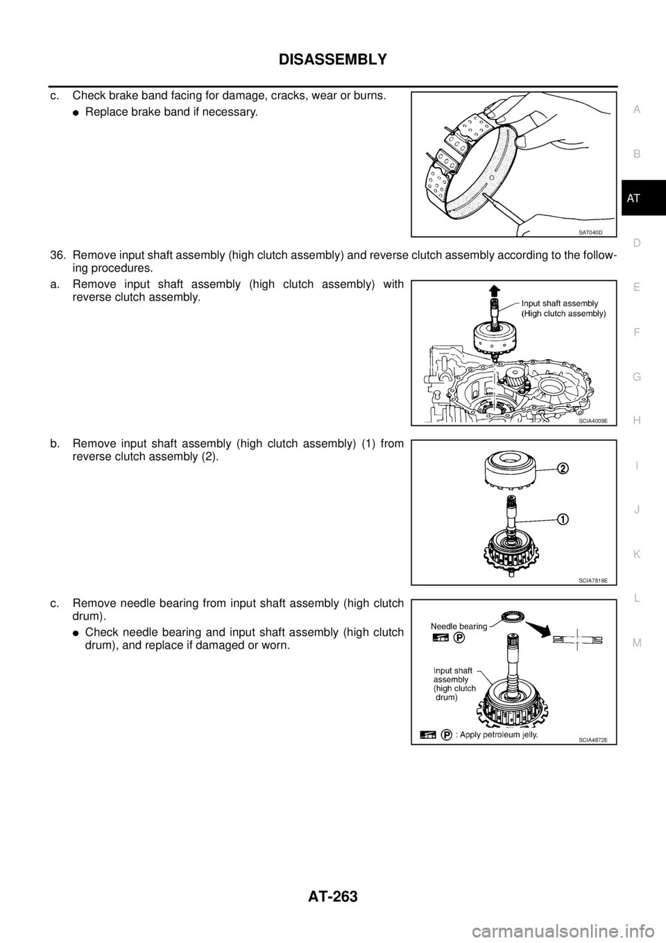
c. Check brake band facing for damage, cracks, wear or burns.
�Replace brake band if necessary.
36. Remove input shaft assembly (high clutch assembly) and reverse clutch assembly according to the follow-
ing procedures.
a. Remove input shaft assembly (high clutch assembly) with
reverse clutch assembly.
b. Remove input shaft assembly (high clutch assembly) (1) from
reverse clutch assembly (2).
c. Remove needle bearing from input shaft assembly (high clutch
drum).
�Check needle bearing and input shaft assembly (high clutch
drum), and replace if damaged or worn.
SAT040D
SCIA4009E
SCIA7818E
SCIA4872E
Page 272 of 3502
AT-264
DISASSEMBLY
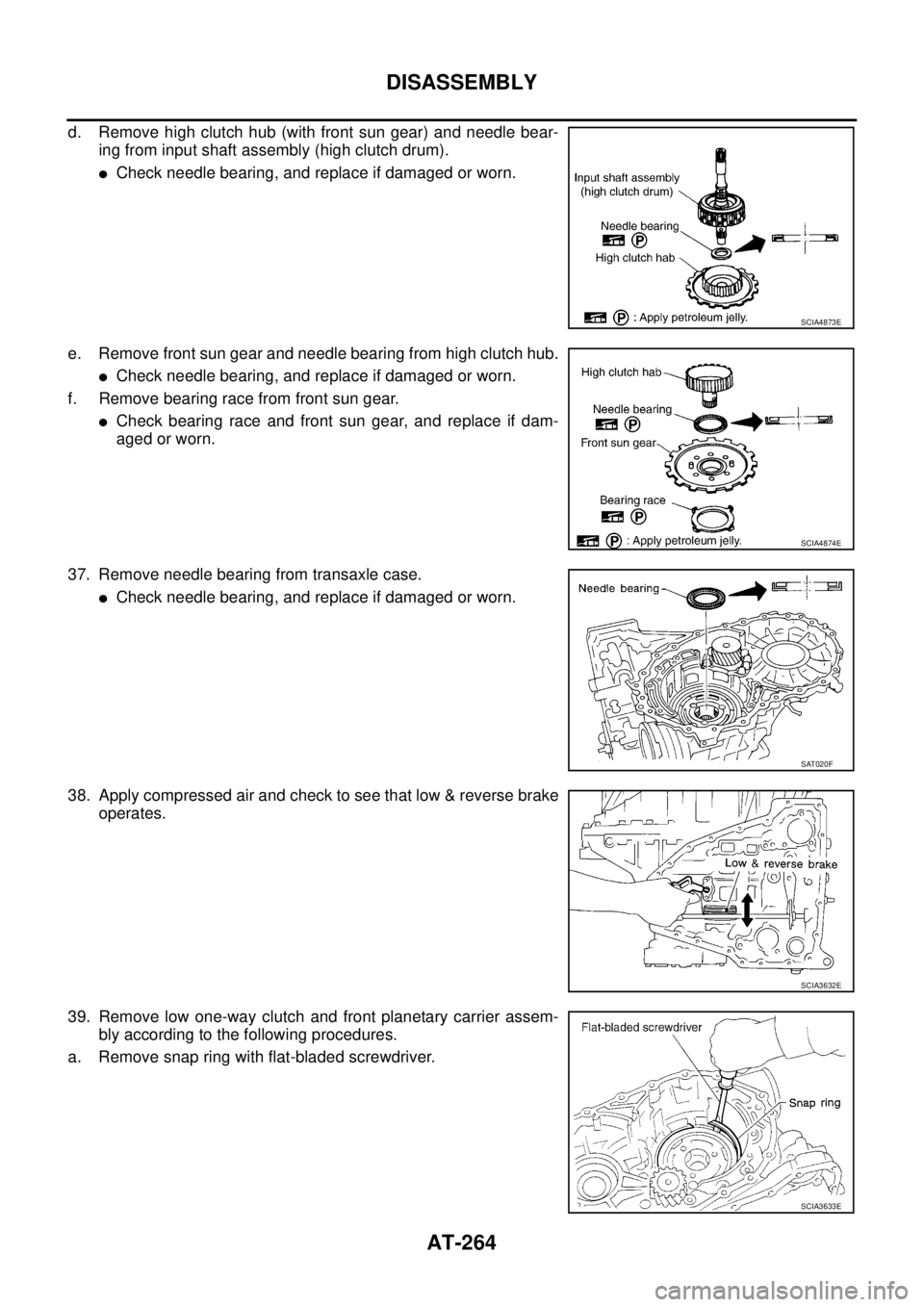
d. Remove high clutch hub (with front sun gear) and needle bear-
ing from input shaft assembly (high clutch drum).
�Check needle bearing, and replace if damaged or worn.
e. Remove front sun gear and needle bearing from high clutch hub.
�Check needle bearing, and replace if damaged or worn.
f. Remove bearing race from front sun gear.
�Check bearing race and front sun gear, and replace if dam-
aged or worn.
37. Remove needle bearing from transaxle case.
�Check needle bearing, and replace if damaged or worn.
38. Apply compressed air and check to see that low & reverse brake
operates.
39. Remove low one-way clutch and front planetary carrier assem-
bly according to the following procedures.
a. Remove snap ring with flat-bladed screwdriver.
SCIA4873E
SCIA4874E
SAT020F
SCIA3632E
SCIA3633E
Page 273 of 3502
DISASSEMBLY
AT-265
D
E
F
G
H
I
J
K
L
MA
B
AT
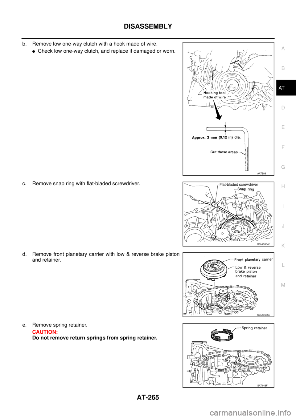
b. Remove low one-way clutch with a hook made of wire.
�Check low one-way clutch, and replace if damaged or worn.
c. Remove snap ring with flat-bladed screwdriver.
d. Remove front planetary carrier with low & reverse brake piston
and retainer.
e. Remove spring retainer.
CAUTION:
Do not remove return springs from spring retainer.
AAT889
SCIA3634E
SCIA3635E
SAT148F
Page 274 of 3502
AT-266
DISASSEMBLY
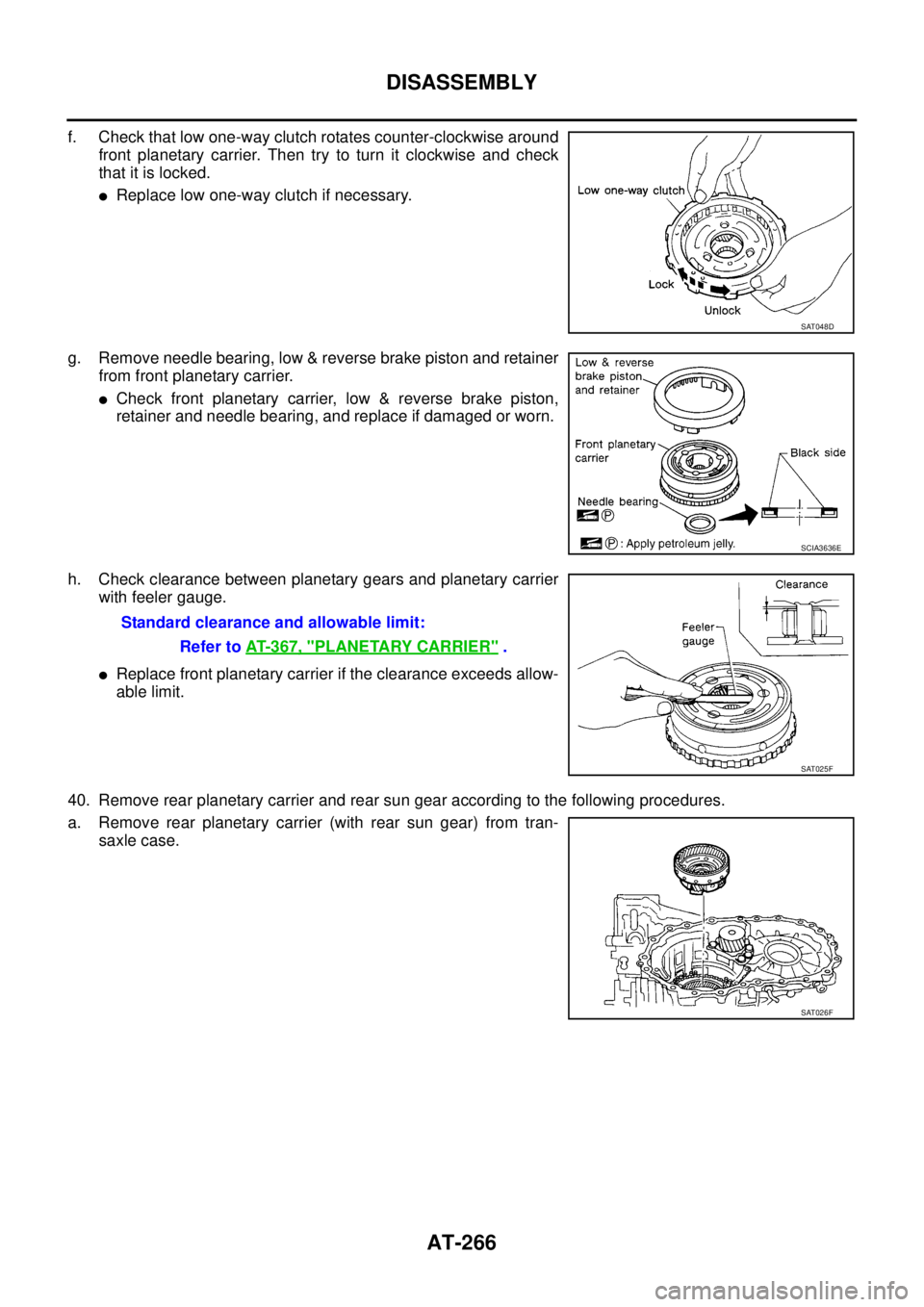
f. Check that low one-way clutch rotates counter-clockwise around
front planetary carrier. Then try to turn it clockwise and check
that it is locked.
�Replace low one-way clutch if necessary.
g. Remove needle bearing, low & reverse brake piston and retainer
from front planetary carrier.
�Check front planetary carrier, low & reverse brake piston,
retainer and needle bearing, and replace if damaged or worn.
h. Check clearance between planetary gears and planetary carrier
with feeler gauge.
�Replace front planetary carrier if the clearance exceeds allow-
able limit.
40. Remove rear planetary carrier and rear sun gear according to the following procedures.
a. Remove rear planetary carrier (with rear sun gear) from tran-
saxle case.
SAT048D
SCIA3636E
Standard clearance and allowable limit:
Refer to AT- 3 6 7 , "
PLANETARY CARRIER" .
SAT025F
SAT026F
Page 323 of 3502
REPAIR FOR COMPONENT PARTS
AT-315
D
E
F
G
H
I
J
K
L
MA
B
AT
Low & Reverse BrakeBCS001OR
COMPONENTS
DISASSEMBLY
1. Check operation of low & reverse brake.
a. Apply compressed air to oil hole of transaxle case.
b. Check to see that retaining plate moves to snap ring.
c. If retaining plate does not contact snap ring:
�D-ring might be damaged.
�Fluid might be leaking past piston check ball.
2. Remove snap ring with flat-bladed screwdriver.
3. Remove low & reverse brake piston (with retainer) and spring
retainer from transaxle case.
4. Remove snap ring with flat-bladed screwdriver.
5. Remove driven plates, drive plates, retaining plates and dish
plates from transaxle case.
1. Driven plate 2. Dish plate 3. Snap ring
4. Spring retainer 5. D-ring 6. D-ring
7. Low & reverse brake piston 8. Retainer 9. Snap ring
10. Retaining plate 11. Drive plate 12. Retaining plate
SCIA3893E
SCIA4903E
SCIA4904E
Page 324 of 3502
AT-316
REPAIR FOR COMPONENT PARTS
6. In order to remove low & reverse brake piston, apply com-
pressed air to oil hole of retainer while holding piston.
CAUTION:
Apply air gradually and allow low & reverse brake piston to
come out evenly.
7. Remove D-rings from low & reverse brake piston.
INSPECTION
Low & Reverse Brake Snap Ring and Spring Retainer
Check for deformation, fatigue or damage. Replace if necessary.
Low & Reverse Brake Drive Plate
�Check facing for burns, cracks or damage. Replace if necessary.
�Measure thickness of facing.
CAUTION:
�Measure the thickness at 3 locations and find the aver-
age.
�Inspect all drive plates.
�Replace if the thickness is below the allowable limit.
ASSEMBLY
1. Install D-rings on low & reverse brake piston.
SCIA3651E
SCIA4381E
Thickness of drive plate
Standard and allowable limit:
Refer to AT- 3 6 6 , "
LOW & REVERSE BRAKE" .
SAT162D
SCIA4381E
Page 325 of 3502
REPAIR FOR COMPONENT PARTS
AT-317
D
E
F
G
H
I
J
K
L
MA
B
AT
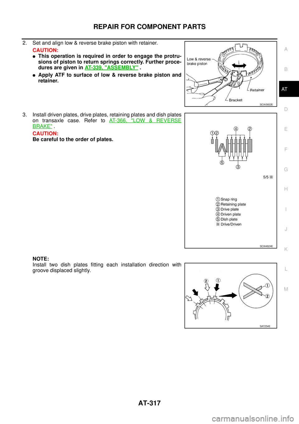
2. Set and align low & reverse brake piston with retainer.
CAUTION:
�This operation is required in order to engage the protru-
sions of piston to return springs correctly. Further proce-
dures are given in AT- 3 3 9 , "
ASSEMBLY" .
�Apply ATF to surface of low & reverse brake piston and
retainer.
3. Install driven plates, drive plates, retaining plates and dish plates
on transaxle case. Refer to AT- 3 6 6 , "
LOW & REVERSE
BRAKE" .
CAUTION:
Be careful to the order of plates.
NOTE:
Install two dish plates fitting each installation direction with
groove displaced slightly.
SCIA3652E
SCIA4624E
SAT254E