Page 3008 of 3502

Checking Fuel LinesBLS0005N
Inspect fuel lines, fuel filler cap and fuel tank for improper attach-
ment, leaks, cracks, damage, loose connections, chafin")
MA-30
ENGINE MAINTENANCE (VQ23DE AND VQ35DE)
Checking Fuel LinesBLS0005N
Inspect fuel lines, fuel filler cap and fuel tank for improper attach-
ment, leaks, cracks, damage, loose connections, chafing or deterio-
ration.
If necessary, repair or replace damaged parts.
Changing Air Cleaner FilterBLS0005O
VISCOUS PAPER TYPE
The viscous paper type filter does not need cleaning between replacement intervals. Refer to MA-8, "PERI-
ODIC MAINTENANCE" .
Removal
1. Unhook air cleaner case (lower) side clips and lift up air cleaner case (upper).
2. Remove air cleaner filter.
Installation
Installation is the reverse order of removal.
Changing Engine OilBLS0005P
WARNING:
�Be careful not to burn yourself, as engine oil may be hot.
�Prolonged and repeated contact with used engine oil may cause skin cancer; try to avoid direct
skin contact with used engine oil. If skin contact is made, wash thoroughly with soap or hand
cleaner as soon as possible.
1. Warm up engine, put vehicle horizontally and check for engine oil leakage from engine components. Refer
to LU-19, "
ENGINE OIL LEAKAGE" .
2. Stop engine and wait for 10 minutes.
3. Loosen oil filler cap and then remove drain plug.
4. Drain engine oil.
5. Install drain plug with new washer. Refer to EM-145, "
OIL PAN AND OIL STRAINER" .
CAUTION:
Be sure to clean drain plug and install with new washer.
6. Refill with new engine oil.
Engine oil specification and viscosity:
Refer to MA-14, "
RECOMMENDED FLUIDS AND LUBRICANTS" .
SMA803A
PBIC2452E
Oil pan drain plug:
: 34.3 N·m (3.5 kg-m, 25 ft-lb)
Page 3009 of 3502

MA-31
C
D
E
F
G
H
I
J
K
MA
B
MA
Engine oil capacity (Approximate):
Unit: (lmp qt)
CAUTION:
�When filling engine oil, do not pull out oil level gauge.
�The r")
ENGINE MAINTENANCE (VQ23DE AND VQ35DE)
MA-31
C
D
E
F
G
H
I
J
K
MA
B
MA
Engine oil capacity (Approximate):
Unit: (lmp qt)
CAUTION:
�When filling engine oil, do not pull out oil level gauge.
�The refill capacity depends on the engine oil temperature and drain time. Use these specifica-
tions for reference only.
�Always use oil level gauge to the determine when the proper amount of engine oil is in the
engine.
NOTE:
The same quantity both VQ23DE and VQ35DE
7. Warm up engine and check area around drain plug and oil filter for engine oil leakage.
8. Stop engine and wait for 10 minutes.
9. Check the engine oil level.
Changing Oil FilterBLS0005Q
REMOVAL
1. Remove splash guard (RH).
2. Using oil filter wrench [SST], remove oil filter.
CAUTION:
�Oil filter is provided with relief valve. Use Genuine Nissan
Oil Filter or equivalent.
�Be careful not to get burned when engine and engine oil
may be hot.
�When removing, prepare a shop cloth to absorb any
engine oil leakage or spillage.
�Do not allow engine oil to adhere to drive belts.
�Completely wipe off any engine oil that adheres to engine
and vehicle.
NOTE:
Figure is shown as an example VQ35DE.
INSTALLATION
1. Remove foreign materials adhering to oil filter installation surface.
Drain and refill With oil filter change 4.0 (3-1/2)
Without oil filter change 3.7 (3-1/4)
Dry engine (Overhaul)5.0 (4-3/8)
PBIC0249E
PBIC1804E
Page 3010 of 3502

2. Apply engine oil to the oil seal contact surface of new oil filter.
3. Screw oil filter manually until it touches the installation surface,
then tight")
MA-32
ENGINE MAINTENANCE (VQ23DE AND VQ35DE)
2. Apply engine oil to the oil seal contact surface of new oil filter.
3. Screw oil filter manually until it touches the installation surface,
then tighten it by 2/3 turn. Or tighten to specification.
INSPECTION AFTER INSTALLATION
1. Check the engine oil level. Refer to MA-30, "Changing Engine Oil" .
2. Start engine, and check there is no leaks of engine oil.
3. Stop engine and wait for 10 minutes.
4. Check the engine oil level and add engine oil. Refer to MA-30, "
Changing Engine Oil" .
Changing Spark Plug (Platinum-Tipped Type)BLS0005R
REMOVAL
1. Remove engine cover. Refer to EM-133, "INTAKE MANIFOLD COLLECTOR" .
2. Remove ignition coil. Refer to EM-152, "
IGNITION COIL" .
3. Remove spark plug using spark plug wrench (commercial ser-
vice tool).
CAUTION:
Do not drop or shock it.
INSPECTION AFTER REMOVAL
Use standard type spark plug for normal condition.
Hot type spark plug is suitable when fouling occurs with standard type spark plug under conditions such as:
�Frequent engine starts
�Low ambient temperatures
Cold type spark plug is suitable when spark plug knock occurs with standard type spark plug under conditions
such as:
�Extended highway driving
�Frequent high engine revolution
SMA010
Oil filter:
: 17.6 N·m (1.8 kg-m, 13 ft-lb)
SMA229B
SEM294A
Page 3011 of 3502
ENGINE MAINTENANCE (VQ23DE AND VQ35DE)
MA-33
C
D
E
F
G
H
I
J
K
MA
B
MA
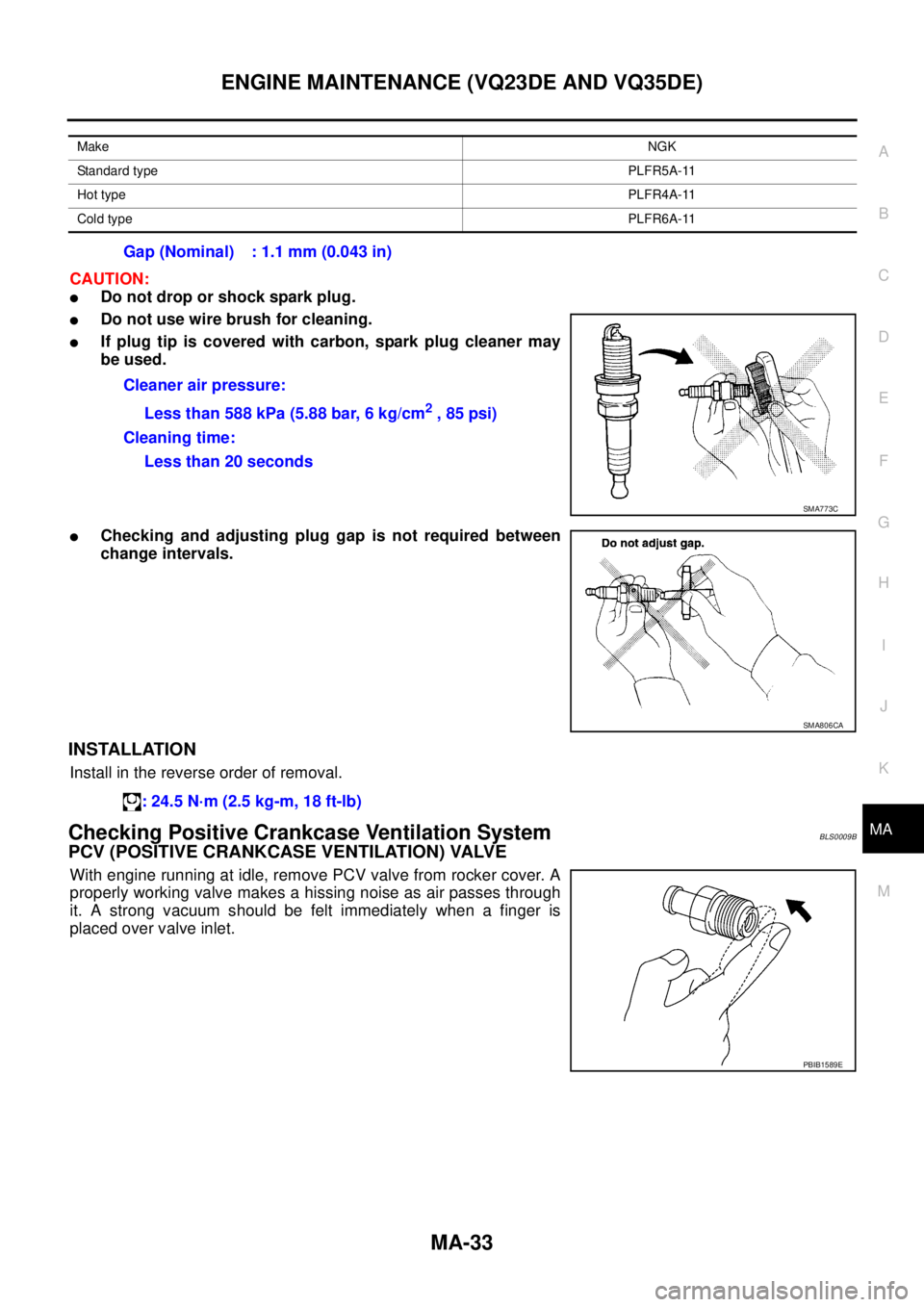
CAUTION:
�Do not drop or shock spark plug.
�Do not use wire brush for cleaning.
�If plug tip is covered with carbon, spark plug cleaner may
be used.
�Checking and adjusting plug gap is not required between
change intervals.
INSTALLATION
Install in the reverse order of removal.
Checking Positive Crankcase Ventilation SystemBLS0009B
PCV (POSITIVE CRANKCASE VENTILATION) VALVE
With engine running at idle, remove PCV valve from rocker cover. A
properly working valve makes a hissing noise as air passes through
it. A strong vacuum should be felt immediately when a finger is
placed over valve inlet.
MakeNGK
Standard typePLFR5A-11
Hot typePLFR4A-11
Cold typePLFR6A-11
Gap (Nominal) : 1.1 mm (0.043 in)
Cleaner air pressure:
Less than 588 kPa (5.88 bar, 6 kg/cm
2 , 85 psi)
Cleaning time:
Less than 20 seconds
SMA773C
SMA806CA
: 24.5 N·m (2.5 kg-m, 18 ft-lb)
PBIB1589E
Page 3012 of 3502
MA-34
ENGINE MAINTENANCE (VQ23DE AND VQ35DE)
PCV VALVE VENTILATION HOSE
1. Check hoses and hose connections for leaks.
2. Disconnect all hoses and clean with compressed air. If any hose
cannot be freed of obstructions, replace.
Checking EVAP Vapor LinesBLS0005S
1. Visually inspect EVAP vapor lines for improper attachment and for cracks, damage, loose connections,
chafing and deterioration.
2. Inspect fuel tank filler cap vacuum relief valve for clogging, sticking, etc.
Refer to EC-366, "
EVAPORATIVE EMISSION SYSTEM" .
S-ET277
Page 3013 of 3502

CHASSIS AND BODY MAINTENANCE
MA-35
C
D
E
F
G
H
I
J
K
MA
B
MA
CHASSIS AND BODY MAINTENANCEPFP:00100
Checking Exhaust SystemBLS0005T
Check exhaust pipes, muffler and mounting for improper attachment,
leaks, cracks, damage, chafing or deterioration.
�If anything is found, repair or replace damaged parts.
Checking A/T FluidBLS0009F
1. Warm up engine.
2. Check for A/T fluid leakage.
3. Before driving, A/T fluid level can be checked A/T at fluid tem-
peratures of 30 to 50°C (86 to 122°F) using “COLD” range on A/
T fluid level gauge.
a. Park vehicle on level surface and set parking brake.
b. Start engine and move selector lever through each gear posi-
tion. Leave selector lever in “P” position.
c. Check A/T fluid level with engine idling.
d. Remove A/T fluid level gauge and wipe clean with lint-free
paper.
CAUTION:
When wiping away the A/T fluid level gauge, always use
lint-free paper, not a cloth one.
e. Re-insert A/T fluid level gauge into A/T fluid charging pipe as far
as it will go.
CAUTION:
Firmly fix the A/T fluid level gauge to the A/T fluid charging
pipe using a stopper attached.
f. Remove A/T fluid level gauge and note reading. If reading is at
low side of range, add ATF to the A/T fluid charging pipe.
CAUTION:
Do not overfill.
4. Drive vehicle for approximately 5 minutes in urban areas.
SMA211A
SMA146B
SCIA3451E
SMA051D
Page 3014 of 3502
 using “HOT” range on A/T
fluid level gauge.
CAUTION:
�When wiping away the")
MA-36
CHASSIS AND BODY MAINTENANCE
5. Recheck A/T fluid level at A/T fluid temperatures of 50 to 80°C (122 to 176°F) using “HOT” range on A/T
fluid level gauge.
CAUTION:
�When wiping away the A/T fluid level gauge, always use lint-free paper, not cloth one.
�Firmly fix the A/T fluid level gauge to the A/T fluid charging pipe using a stopper attached.
6. Check A/T fluid condition.
�If ATF is very dark or smells burned, checking operation of A/
T. Flush cooling system after repair of A/T.
�If ATF contains frictional material (clutches, bands, etc.),
replace radiator and flush cooler line using cleaning solvent
and compressed air after repair of A/T. Refer to CO-37,
"RADIATOR" , CO-40, "RADIATOR (ALUMINUM TYPE)" .
7. Install the removed A/T fluid level gauge in the A/T fluid charging
pipe.
CAUTION:
Firmly fix the A/T fluid level gauge to the A/T fluid charging
pipe using a stopper attached.
Changing A/T FluidBLS0009G
1. Warm up ATF.
2. Stop engine.
3. Drain ATF from drain plug and refill with new ATF. Always refill same volume with drained ATF.
CAUTION:
Do not reuse drain plug gasket.
4. Run engine at idle speed for 5 minutes.
5. Check A/T fluid level and condition. Refer to MA-35, "
Checking A/T Fluid" . If ATF is still dirty, repeat steps
2 through 5.
Checking CVT FluidBLS0009H
Fluid level should be checked with the fluid warmed up to 50 to 80°C (122 to 176°F). The fluid level check pro-
cedure is as follows:
SAT638A
Fluid grade:
Genuine NISSAN ATF Matic Fluid D or equivalent.
Refer to MA-14, "
RECOMMENDED FLUIDS AND LUBRICANTS"
.
Fluid capacity
For QR20DE engine models
: Approx. 8.4 (7-3/8 lmp qt)
For VQ23DE engine models
: Approx. 8.9 (7-7/8 lmp qt)
Drain plug:
: 34 N·m (3.5 kg-m, 25 ft-lb)
Page 3015 of 3502
,")
CHASSIS AND BODY MAINTENANCE
MA-37
C
D
E
F
G
H
I
J
K
MA
B
MA
1. Check for fluid leakage.
2. With the engine warmed up, drive the vehicle in an urban area.
When ambient temperature is 20°C (68°F), it takes about 10
minutes for the CVT fluid to warm up to 50 to 80°C (122 to
176°F).
3. Park the vehicle on a level surface.
4. Apply parking brake firmly.
5. With engine at idle, while depressing brake pedal, move shift
selector throughout the entire shift range.
6. Pull out the CVT fluid level gauge from the CVT fluid charging
pipe after pressing the tab on the CVT fluid level gauge to
release the lock.
7. Wipe fluid off the CVT fluid level gauge. Insert the CVT fluid
level gauge rotating 180° from the originally installed position,
then securely push the CVT fluid level gauge until it meets the
top end of the CVT fluid charging pipe.
CAUTION:
When wiping away the CVT fluid level gauge, always use
lint-free paper, not a cloth rag.
8. Place the selector lever in “P” or “N” and make sure the fluid
level is within the specified range.
CAUTION:
When reinstalling CVT fluid level gauge, insert it into the
CVT fluid charging pipe and rotate it to the original installa-
tion position until it is securely locked.
9. Check CVT fluid condition.
�If CVT fluid is very dark or smells burned, check operation of
CVT. Flush cooling system after repair of CVT.
�If CVT fluid contains frictional material (clutches, bands, etc.),
replace radiator and flush cooler line using cleaning solvent
and compressed air after repair of CVT. Refer to CO-37,
"RADIATOR" .
SMA146B
SCIA1933E
SCIA1931E
SCIA1932E
ATA0022D

PCV VALVE VENTILATION HOSE
1. Check hoses and hose connections for leaks.
2. Disconnect all hoses and clean with compressed air. If any hose
cannot be fr")