Page 2342 of 3502
![NISSAN TEANA 2003 Service Manual EM-234
[VQ]
CYLINDER BLOCK
2. Install each plug to cylinder block as shown in the figure.
NOTE:
Water drain plug at the right bank side for VQ35DE is also used
as a connector of water pipe for oil c NISSAN TEANA 2003 Service Manual EM-234
[VQ]
CYLINDER BLOCK
2. Install each plug to cylinder block as shown in the figure.
NOTE:
Water drain plug at the right bank side for VQ35DE is also used
as a connector of water pipe for oil c](/manual-img/5/57392/w960_57392-2341.png)
EM-234
[VQ]
CYLINDER BLOCK
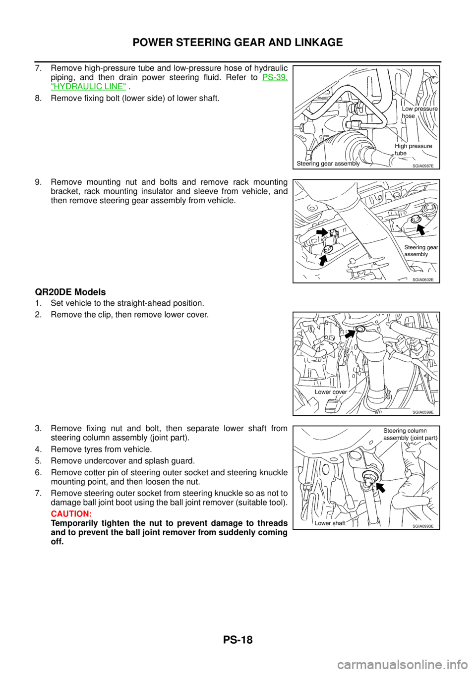
2. Install each plug to cylinder block as shown in the figure.
NOTE:
Water drain plug at the right bank side for VQ35DE is also used
as a connector of water pipe for oil cooler. Refer to LU-23, "
OIL
COOLER (VQ35DE)" .
�Apply sealant to the thread of water drain plug “A”.
Use Anaerobic Liquid Gasket or equivalent.
�Apply sealant to the thread of water drain plugs “B” and “D”.
Use Genuine Liquid Gasket or equivalent.
�Apply sealant to the thread of plug “C”.
Use Thread Locking Sealant or equivalent.
�Replace washers with new one.
�Tighten each plug as specified below.
3. Install oil jet. (VQ35DE)
�Insert oil jet dowel pin into cylinder block dowel pin hole, and
tighten mounting bolts.
4. Install main bearings and thrust bearings as follows:
a. Remove dust, dirt, and engine oil on bearing mating surfaces of cylinder block and main bearing caps.
PBIC2487E
Part WasherTightening torque
VQ23DE VQ35DE
A Yes 62.0 N·m (6.3 kg-m, 46 ft-lb)
B No 9.8 N·m (1.0 kg-m, 87 in-lb)
C Yes 62.0 N·m (6.3 kg-m, 46 ft-lb)
D No 19.6 N·m (2.0 kg-m, 14 ft-lb) 39.2 N·m (4.0 kg-m, 29 ft-lb)
PBIC2488E
Page 2973 of 3502
![NISSAN TEANA 2003 Service Manual OIL COOLER (VQ35DE)
LU-23
[VQ]
C
D
E
F
G
H
I
J
K
L
MA
LU
OIL COOLER (VQ35DE)PFP:21305
Removal and InstallationBBS004WN
�Refer to GI-10, "Components" for symbol marks in the figure.
WARNING:
Be care NISSAN TEANA 2003 Service Manual OIL COOLER (VQ35DE)
LU-23
[VQ]
C
D
E
F
G
H
I
J
K
L
MA
LU
OIL COOLER (VQ35DE)PFP:21305
Removal and InstallationBBS004WN
�Refer to GI-10, "Components" for symbol marks in the figure.
WARNING:
Be care](/manual-img/5/57392/w960_57392-2972.png)
OIL COOLER (VQ35DE)
LU-23
[VQ]
C
D
E
F
G
H
I
J
K
L
MA
LU
OIL COOLER (VQ35DE)PFP:21305
Removal and InstallationBBS004WN
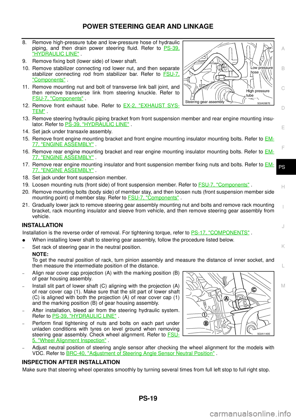
�Refer to GI-10, "Components" for symbol marks in the figure.
WARNING:
Be careful not to get burn yourself, as engine oil and engine coolant may be hot.
REMOVAL
NOTE:
When removing oil cooler only, step 2 is unnecessary.
1. Remove splash guard (RH).
2. Drain engine coolant from radiator and cylinder block. Refer to CO-34, "
Changing Engine Coolant" and
EM-229, "
DISASSEMBLY" .
NOTE:
Perform this step when removing water pipes.
3. Remove oil filter. Refer to LU-22, "
OIL FILTER" .
CAUTION:
Do not spill engine oil on drive belts.
4. Disconnect water hoses from oil cooler.
�When removing oil cooler only, pinching water hoses near oil cooler to prevent engine coolant spilling.
1. Connector bolt 2. Copper gasket 3. Water drain plug
4. Water pipe 5. Bracket 6. Water hose
7. Relief valve 8. O-ring 9. Oil cooler
10. Connector bolt 11. Oil filter 12. Water hose
13. Water pipe 14. Clamp 15. Water hose
16. Clamp
A. Refer to LU-22
:Engine front
PBIC4731E
Page 3132 of 3502

PS-18
POWER STEERING GEAR AND LINKAGE
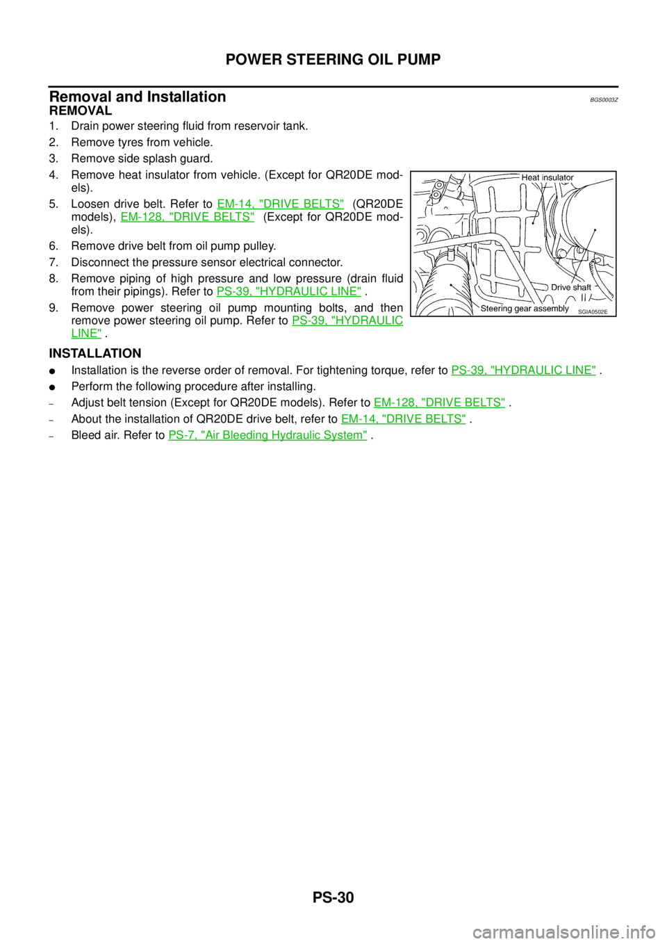
7. Remove high-pressure tube and low-pressure hose of hydraulic
piping, and then drain power steering fluid. Refer to PS-39,
"HYDRAULIC LINE" .
8. Remove fixing bolt (lower side) of lower shaft.
9. Remove mounting nut and bolts and remove rack mounting
bracket, rack mounting insulator and sleeve from vehicle, and
then remove steering gear assembly from vehicle.
QR20DE Models
1. Set vehicle to the straight-ahead position.
2. Remove the clip, then remove lower cover.
3. Remove fixing nut and bolt, then separate lower shaft from
steering column assembly (joint part).
4. Remove tyres from vehicle.
5. Remove undercover and splash guard.
6. Remove cotter pin of steering outer socket and steering knuckle
mounting point, and then loosen the nut.
7. Remove steering outer socket from steering knuckle so as not to
damage ball joint boot using the ball joint remover (suitable tool).
CAUTION:
Temporarily tighten the nut to prevent damage to threads
and to prevent the ball joint remover from suddenly coming
off.
SGIA0987E
SGIA0602E
SGIA0599E
SGIA0993E
Page 3133 of 3502

POWER STEERING GEAR AND LINKAGE
PS-19
C
D
E
F
H
I
J
K
L
MA
B
PS
8. Remove high-pressure tube and low-pressure hose of hydraulic
piping, and then drain power steering fluid. Refer to PS-39,
"HYDRAULIC LINE" .
9. Remove fixing bolt (lower side) of lower shaft.
10. Remove stabilizer connecting rod lower nut, and then separate
stabilizer connecting rod from stabilizer bar. Refer to FSU-7,
"Components" .
11. Remove mounting nut and bolt of transverse link ball joint, and
then remove transverse link from steering knuckle. Refer to
FSU-7, "
Components" .
12. Remove front exhaust tube. Refer to EX-2, "
EXHAUST SYS-
TEM" .
13. Remove steering hydraulic piping bracket from front suspension member and rear engine mounting insu-
lator. Refer to PS-39, "
HYDRAULIC LINE" .
14. Set jack under transaxle assembly.
15. Remove front engine mounting bracket and front engine mounting insulator mounting bolts. Refer to EM-
77, "ENGINE ASSEMBLY" .
16. Remove rear engine mounting bracket and rear engine mounting insulator mounting bolts. Refer to EM-
77, "ENGINE ASSEMBLY" .
17. Remove rear engine mounting insulator and front suspension member fixing nuts and bolts. Refer to EM-
77, "ENGINE ASSEMBLY" .
18. Set jack under front suspension member.
19. Loosen mounting nuts (front side) of front suspension member. Refer to FSU-7, "
Components" .
20. Remove mounting bolts (body side) of member stay, and then loosen nuts (front suspension member side
mounting point) of member stay. Refer to FSU-7, "
Components" .
21. Gradually lower jack to remove steering gear assembly mounting nut and bolts and remove rack mounting
bracket, rack mounting insulator and sleeve from vehicle, and then remove steering gear assembly from
vehicle.
INSTALLATION
Installation is the reverse order of removal. For tightening torque, refer to PS-17, "COMPONENTS" .
�When installing lower shaft to steering gear assembly, follow the procedure listed below.
–Set rack of steering gear in the neutral position.
NOTE:
To get the neutral position of rack, turn pinion assembly and measure the distance of inner socket, and
then measure the intermediate position of the distance.
–Align rear cover cap projection (A) with the marking position (B)
of gear housing assembly.
–Install slit part of lower shaft (C) aligning with the projection (A)
of rear cover cap (1). Make sure that the slit part of lower shaft
(C) is aligned with both the projection (A) of rear cover cap (1)
and the marking position (B) of gear housing assembly.
–After installation, bleed air from the steering hydraulic system.
Refer to PS-39, "
HYDRAULIC LINE" .
–Perform final tightening of nuts and bolts on each part under
unladen conditions with tyres on level ground when removing
steering gear assembly. Check wheel alignment. Refer to FSU-
5, "Wheel Alignment Inspection" .
–Adjust neutral position of steering angle sensor after checking the wheel alignment for the models with
VDC. Refer to BRC-40, "
Adjustment of Steering Angle Sensor Neutral Position" .
INSPECTION AFTER INSTALLATION
Make sure that steering wheel operates smoothly by turning several times from full left stop to full right stop.
SGIA0987E
SGIA1140E
Page 3144 of 3502

PS-30
POWER STEERING OIL PUMP
Removal and InstallationBGS0003Z
REMOVAL
1. Drain power steering fluid from reservoir tank.
2. Remove tyres from vehicle.
3. Remove side splash guard.
4. Remove heat insulator from vehicle. (Except for QR20DE mod-
els).
5. Loosen drive belt. Refer to EM-14, "
DRIVE BELTS" (QR20DE
models), EM-128, "
DRIVE BELTS" (Except for QR20DE mod-
els).
6. Remove drive belt from oil pump pulley.
7. Disconnect the pressure sensor electrical connector.
8. Remove piping of high pressure and low pressure (drain fluid
from their pipings). Refer to PS-39, "
HYDRAULIC LINE" .
9. Remove power steering oil pump mounting bolts, and then
remove power steering oil pump. Refer to PS-39, "
HYDRAULIC
LINE" .
INSTALLATION
�Installation is the reverse order of removal. For tightening torque, refer to PS-39, "HYDRAULIC LINE" .
�Perform the following procedure after installing.
–Adjust belt tension (Except for QR20DE models). Refer to EM-128, "DRIVE BELTS" .
–About the installation of QR20DE drive belt, refer to EM-14, "DRIVE BELTS" .
–Bleed air. Refer to PS-7, "Air Bleeding Hydraulic System" .
SGIA0502E
Page 3188 of 3502

RF-24
SUNROOF
SUNROOF UNIT ASSEMBLY
Removal
CAUTION:
�Always work with a helper.
�When taking sunroof unit out, use clothes to protect the seats and trim from damage.
�After installing the sunroof unit and glass lid, be sure to perform the leakage test and make sure
there is no malfunction.
1. Tilt up glass lid.
2. Remove the headlining. Refer to EI-54, "
Removal and Installation" .
3. Disconnect drain hoses.
4. Remove glass lid. Refer to RF-25, "
GLASS LID" .
5. Disconnect harness connector from sunroof motor assembly.
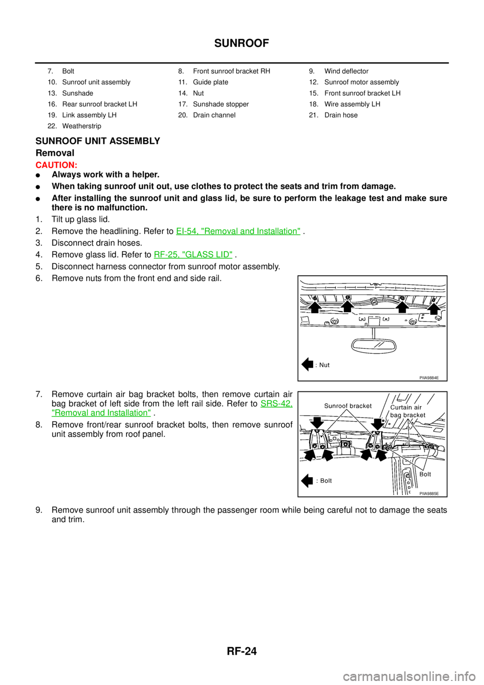
6. Remove nuts from the front end and side rail.
7. Remove curtain air bag bracket bolts, then remove curtain air
bag bracket of left side from the left rail side. Refer to SRS-42,
"Removal and Installation" .
8. Remove front/rear sunroof bracket bolts, then remove sunroof
unit assembly from roof panel.
9. Remove sunroof unit assembly through the passenger room while being careful not to damage the seats
and trim.
7. Bolt 8. Front sunroof bracket RH 9. Wind deflector
10. Sunroof unit assembly 11. Guide plate 12. Sunroof motor assembly
13. Sunshade 14. Nut 15. Front sunroof bracket LH
16. Rear sunroof bracket LH 17. Sunshade stopper 18. Wire assembly LH
19. Link assembly LH 20. Drain channel 21. Drain hose
22. Weatherstrip
PIIA9884E
PIIA9885E