Page 2694 of 3502
 controls low beam headlamp")
LT-6
HEADLAMP - XENON TYPE -
HEADLAMP - XENON TYPE -PFP:26010
Component Parts and Harness Connector LocationBKS001MU
System DescriptionBKS001MV
�BCM (Body Control Module) controls low beam headlamp and high beam headlamp operation.
�IPDM E/R (Intelligent Power Distribution Module Engine Room) operates headlamp bulbs and high beam
solenoids according to CAN communication signals from BCM.
�Unified meter and A/C amp. operates high beam indicator according to CAN communication signals from
BCM.
OUTLINE
Power is supplied at all times
�to headlamp high relay (located in IPDM E/R)
�to headlamp low relay (located in IPDM E/R) and
�to ignition relay (located in IPDM E/R), from battery direct,
�through 15A fuse (No. 71, located in IPDM E/R)
�to CPU (central processing unit) in IPDM E/R,
�through 15A fuse (No. 78, located in IPDM E/R)
�to CPU in IPDM E/R,
�through 50A fusible link (letter M, located in fuse and fusible link block)
�to BCM terminal 55,
�through 15A fuse [No. 17, located in fuse block (J/B)]
�to BCM terminal 42 and
�to combination meter terminal 7.
PKID0043E
Page 2726 of 3502
 controls low beam head")
LT-38
HEADLAMP - HALOGEN TYPE -
HEADLAMP - HALOGEN TYPE -PFP:26010
Component Parts and Harness Connector LocationBKS001NJ
System DescriptionBKS001NK
�BCM (Body Control Module) controls low beam headlamp and high beam headlamp operation.
�IPDM E/R (Intelligent Power Distribution Module Engine Room) operates headlamp bulbs according to
CAN communication signals from BCM.
�Unified meter and A/C amp. operates high beam indicator lamp according to CAN communication signals
from BCM.
OUTLINE
Power is supplied at all times
�to headlamp high relay (located in IPDM E/R)
�to headlamp low relay (located in IPDM E/R) and
�to ignition relay (located in IPDM E/R), from battery direct,
�through 15A fuse (No. 71, located in IPDM E/R)
�to CPU (central processing unit) in IPDM E/R,
�through 15A fuse (No. 78, located in IPDM E/R)
�to CPU in IPDM E/R,
�through 50A fusible link (letter M, located in fuse and fusible link block)
�to BCM terminal 55,
�through 15A fuse [No. 17, located in fuse block (J/B)]
�to BCM terminal 42 and
�to combination meter terminal 7.
PKID0043E
Page 2752 of 3502
 controls auto light operation accordin")
LT-64
AUTO LIGHT SYSTEM
AUTO LIGHT SYSTEMPFP:28491
Component Parts and Harness Connector LocationBKS001O5
System DescriptionBKS001O6
�BCM (Body Control Module) controls auto light operation according to signals from optical sensor, lighting
switch and ignition switch.
�IPDM E/R (Intelligent Power Distribution Module Engine Room) operates parking, license plate, tail, front
fog lamps and headlamps according to CAN communication signals from BCM.
�Optical sensor detects ambient brightness of 800 to 2,500 lux. And optical sensor converts light (lux) to
voltage, then sends the optical sensor signal to BCM.
OUTLINE
The auto light control system has an optical sensor inside it that detects outside brightness.
When the lighting switch is in AUTO position, it automatically turns ON/OFF the parking, license plate, tail,
front fog lamps and headlamps in accordance with the ambient light. Sensitivity can be adjusted in four steps.
For the details of the setting, Refer to LT- 1 9 , "
WORK SUPPORT" .
Optical sensor, power is supplied
�from BCM terminal 17
�to optical sensor terminal 1.
Optical sensor, ground is supplied
�to optical sensor terminal 3
�from BCM terminal 18.
When ignition switch is turn to ON position, and
When outside brightness is darker than prescribed level, input is supplied
�from optical sensor terminal 2
PKID0343E
Page 2814 of 3502
 controls front fog lamp operation.
�IPDM E/")
LT-126
FRONT FOG LAMP
FRONT FOG LAMPPFP:26150
Component Parts and Harness Connector LocationBKS001OP
System DescriptionBKS001OQ
�BCM (Body Control Module) controls front fog lamp operation.
�IPDM E/R (Intelligent Power Distribution Module Engine Room) operates front fog lamp according to CAN
communication signals from BCM.
�Unified meter and A/C amp. operates front fog lamp indicator according to CAN communication signals.
OUTLINE
Power is supplied at all times
�to ignition relay (located in IPDM E/R), from battery direct,
�through 15A fuse (No. 88, located in IPDM E/R)
�to front fog lamp relay (located in IPDM E/R),
�through 15A fuse (No. 71, located in IPDM E/R)
�to CPU (central processing unit) located in IPDM E/R,
�through 15A fuse (No. 78, located in IPDM E/R)
�to CPU located in IPDM E/R,
�through 50A fusible link (letter M, located in fuse and fusible link block)
�to BCM terminal 55,
�through 15A fuse [No. 17, located in fuse block (J/B)]
�to BCM terminal 42 and
�to combination meter terminal 7.
PKID0046E
Page 2830 of 3502
LT-142
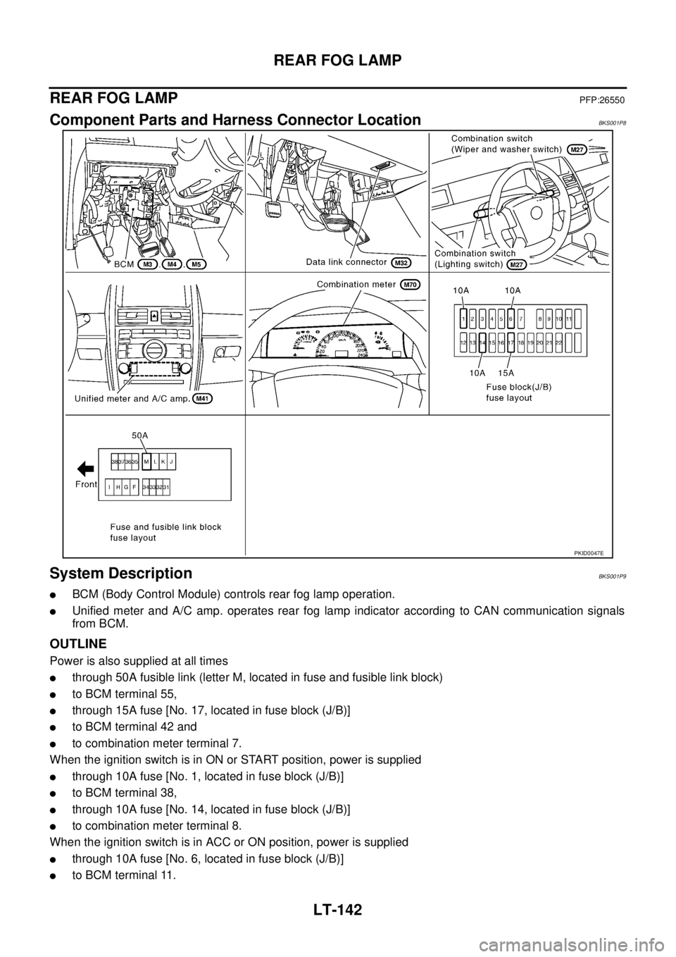
REAR FOG LAMP
REAR FOG LAMPPFP:26550
Component Parts and Harness Connector LocationBKS001P8
System DescriptionBKS001P9
�BCM (Body Control Module) controls rear fog lamp operation.
�Unified meter and A/C amp. operates rear fog lamp indicator according to CAN communication signals
from BCM.
OUTLINE
Power is also supplied at all times
�through 50A fusible link (letter M, located in fuse and fusible link block)
�to BCM terminal 55,
�through 15A fuse [No. 17, located in fuse block (J/B)]
�to BCM terminal 42 and
�to combination meter terminal 7.
When the ignition switch is in ON or START position, power is supplied
�through 10A fuse [No. 1, located in fuse block (J/B)]
�to BCM terminal 38,
�through 10A fuse [No. 14, located in fuse block (J/B)]
�to combination meter terminal 8.
When the ignition switch is in ACC or ON position, power is supplied
�through 10A fuse [No. 6, located in fuse block (J/B)]
�to BCM terminal 11.
PKID0047E
Page 2840 of 3502
")
LT-152
TURN SIGNAL AND HAZARD WARNING LAMPS
TURN SIGNAL AND HAZARD WARNING LAMPSPFP:26120
Component Parts and Harness Connector LocationBKS001PM
System DescriptionBKS001PN
�BCM (Body Control Module) controls turn signal lamp (RH and LH) and hazard warning lamp operation.
�Unified meter and A/C amp. operates turn (RH and LH) indicator according to CAN communication sig-
nals from BCM.
OUTLINE
Power is supplied at all times
�through 50A fusible link (letter M, located in fuse and fusible link block)
�to BCM terminal 55,
�through 15A fuse [No. 17, located in fuse block (J/B)]
�to BCM terminal 42 and
�to combination meter terminal 7.
With the ignition switch in the ON or START position, power is supplied
�through 10A fuse [No. 1, located in fuse block (J/B)]
�to BCM terminal 38,
�through 10A fuse [No. 14, located in fuse block (J/B)]
�to combination meter terminal 8.
With the ignition switch in the ACC or ON position, power is supplied
�through 10A fuse [No. 6, located in fuse block (J/B)]
�to BCM terminal 11.
PKIB0249E
Page 2884 of 3502

LT-196
PARKING, LICENSE PLATE AND TAIL LAMPS
PARKING, LICENSE PLATE AND TAIL LAMPSPFP:26550
Component Parts and Harness Connector LocationBKS001QJ
System DescriptionBKS001QK
�BCM (Body Control Module) controls parking, license plate and tail lamps operation.
�IPDM E/R (Intelligent Power Distribution Module Engine Room) operates parking, license plate and tail
lamps according to CAN communication signals from BCM.
�Unified meter and A/C amp. operates tail lamp indicator according to CAN communication signals from
BCM.
OUTLINE
Power is supplied at all times
�to ignition relay (located in IPDM E/R), from battery direct,
�through 15A fuse (No. 71, located in IPDM E/R)
�to tail lamp relay (located in IPDM E/R) and
�to CPU (central processing unit) in IPDM E/R,
�through 15A fuse (No. 78, located in IPDM E/R)
�to CPU in IPDM E/R,
�through 50A fusible link (letter M, located in fuse and fusible link block)
�to BCM terminal 55,
�through 15A fuse [No. 17, located in fuse block (J/B)]
�to BCM terminal 42 and
�to combination meter terminal 7,
�through 10A fuse [No.19, located in fuse block (J/B)]
PKID0048E
Page 2907 of 3502
INTERIOR ROOM LAMP
LT-219
C
D
E
F
G
H
I
J
L
MA
B
LT
INTERIOR ROOM LAMPPFP:26410
Component Parts and Harness Connector LocationBKS001R4
System DescriptionBKS001R5
BCM (Body Control Module) controls the step lamp, the trunk room lamp, the interior room lamp timer and the
interior room lamp battery saver.
OUTLINE
Power is supplied at all times (without Intelligent Key system)
�through 15A fuse [No. 17, located in fuse block (J/B)]
�to key switch and key lock solenoid (key switch) terminal 1 and
�to BCM terminal 42,
�through 50A fusible link (letter M, located in fuse and fusible link block)
�to BCM terminal 55.
PKID0347E
 controls t")