Page 2242 of 3502
![NISSAN TEANA 2003 Service Manual EM-134
[VQ]
INTAKE MANIFOLD COLLECTOR
�Refer to GI-10, "Components" for symbol marks in the figure.
NOTE:
The figure illustrates VQ35DE as an example. Each part form of VQ23DE is different from VQ](/manual-img/5/57392/w960_57392-2241.png "NISSAN TEANA 2003 Service Manual EM-134
[VQ]
INTAKE MANIFOLD COLLECTOR
�Refer to GI-10, \"Components\" for symbol marks in the figure.
NOTE:
The figure illustrates VQ35DE as an example. Each part form of VQ23DE is different from VQ")
EM-134
[VQ]
INTAKE MANIFOLD COLLECTOR
�Refer to GI-10, "Components" for symbol marks in the figure.
NOTE:
The figure illustrates VQ35DE as an example. Each part form of VQ23DE is different from VQ35DE for differ-
ence of port diameter and so forth. Only portions which structures (components) differ are illustrated.
REMOVAL
WARNING:
To avoid the danger of being scalded, do not drain engine coolant when engine is hot.
NOTE:
Show VQ35DE as an example unless the figure includes specification.
1. Remove engine cover.
CAUTION:
Be careful not to damage or scratch engine cover.
2. Remove air cleaner case (upper) with mass air flow sensor and air duct assembly. Refer to EM-131, "
AIR
CLEANER AND AIR DUCT" .
3. Drain engine coolant, or when water hoses are disconnected, attach plug to prevent engine coolant leak-
age. Refer to CO-34, "
Changing Engine Coolant" .
CAUTION:
Perform this step when engine is cold.
4. Remove electric throttle control actuator as follows:
a. Disconnect harness connector.
b. Loosen mounting bolts in the reverse order as shown in the fig-
ure.
CAUTION:
�Handle carefully to avoid any shock to electric throttle
control actuator.
�Do not disassemble.
5. Disconnect water hoses from intake manifold collector (upper).
�When engine coolant is not drained from radiator, attach plug to water hoses to prevent engine coolant
leakage.
PBIC2454E
KBIA2007J
Page 2243 of 3502
INTAKE MANIFOLD COLLECTOR
EM-135
[VQ]
C
D
E
F
G
H
I
J
K
L
MA
EM
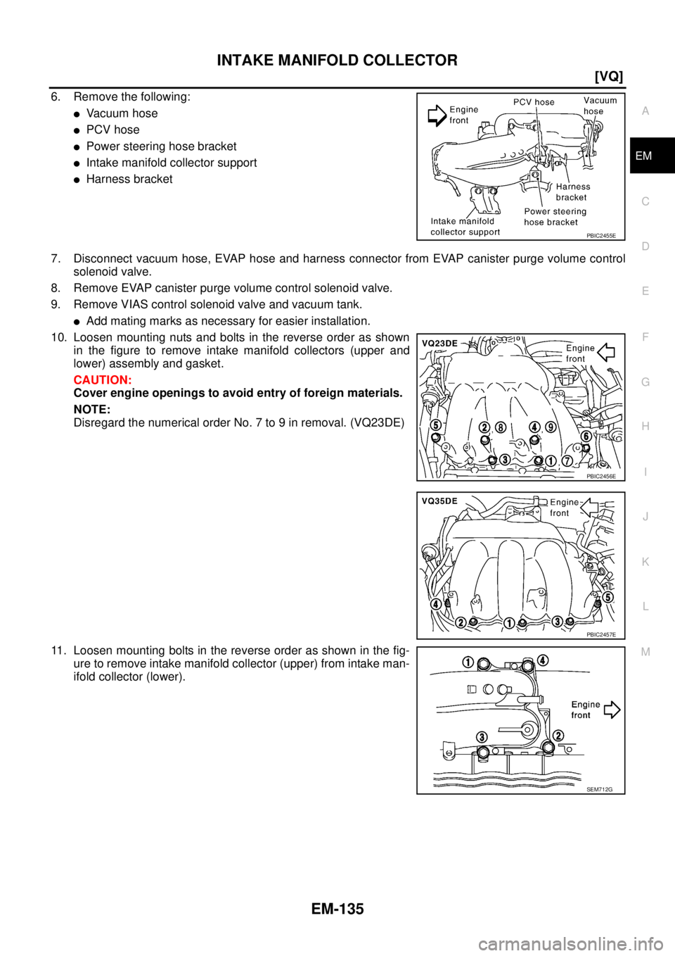
6. Remove the following:
�Va c u u m h o s e
�PCV hose
�Power steering hose bracket
�Intake manifold collector support
�Harness bracket
7. Disconnect vacuum hose, EVAP hose and harness connector from EVAP canister purge volume control
solenoid valve.
8. Remove EVAP canister purge volume control solenoid valve.
9. Remove VIAS control solenoid valve and vacuum tank.
�Add mating marks as necessary for easier installation.
10. Loosen mounting nuts and bolts in the reverse order as shown
in the figure to remove intake manifold collectors (upper and
lower) assembly and gasket.
CAUTION:
Cover engine openings to avoid entry of foreign materials.
NOTE:
Disregard the numerical order No. 7 to 9 in removal. (VQ23DE)
11. Loosen mounting bolts in the reverse order as shown in the fig-
ure to remove intake manifold collector (upper) from intake man-
ifold collector (lower).
PBIC2455E
PBIC2456E
PBIC2457E
SEM712G
Page 2247 of 3502
INTAKE MANIFOLD
EM-139
[VQ]
C
D
E
F
G
H
I
J
K
L
MA
EM
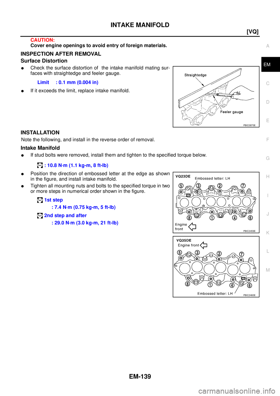
CAUTION:
Cover engine openings to avoid entry of foreign materials.
INSPECTION AFTER REMOVAL
Surface Distortion
�Check the surface distortion of the intake manifold mating sur-
faces with straightedge and feeler gauge.
�If it exceeds the limit, replace intake manifold.
INSTALLATION
Note the following, and install in the reverse order of removal.
Intake Manifold
�If stud bolts were removed, install them and tighten to the specified torque below.
�Position the direction of embossed letter at the edge as shown
in the figure, and install intake manifold.
�Tighten all mounting nuts and bolts to the specified torque in two
or more steps in numerical order shown in the figure.Limit : 0.1 mm (0.004 in)
PBIC0870E
: 10.8 N·m (1.1 kg-m, 8 ft-lb)
1st step
: 7.4 N·m (0.75 kg-m, 5 ft-lb)
2nd step and after
: 29.0 N·m (3.0 kg-m, 21 ft-lb)
PBIC2459E
PBIC2460E
Page 2248 of 3502
![NISSAN TEANA 2003 Service Manual EM-140
[VQ]
EXHAUST MANIFOLD AND THREE WAY CATALYST
EXHAUST MANIFOLD AND THREE WAY CATALYSTPFP:14004
Removal and InstallationBBS004VT
REMOVAL
WARNING:
Perform the work when the exhaust and cooling s](/manual-img/5/57392/w960_57392-2247.png "NISSAN TEANA 2003 Service Manual EM-140
[VQ]
EXHAUST MANIFOLD AND THREE WAY CATALYST
EXHAUST MANIFOLD AND THREE WAY CATALYSTPFP:14004
Removal and InstallationBBS004VT
REMOVAL
WARNING:
Perform the work when the exhaust and cooling s")
EM-140
[VQ]
EXHAUST MANIFOLD AND THREE WAY CATALYST
EXHAUST MANIFOLD AND THREE WAY CATALYSTPFP:14004
Removal and InstallationBBS004VT
REMOVAL
WARNING:
Perform the work when the exhaust and cooling system have completely cooled down.
1. Drain engine coolant. Refer to CO-34, "
Changing Engine Coolant" .
CAUTION:
�Perform this step when engine is cold.
�Do not spill engine coolant on drive belts.
2. Remove the following:
�Engine cover; Refer to EM-133, "INTAKE MANIFOLD COLLECTOR" .
�Air duct (inlet), air cleaner cases (upper and lower) with mass air flow sensor and air duct assembly;
Refer to EM-131, "
AIR CLEANER AND AIR DUCT" .
�Undercover
�Radiator and radiator cooling fan assembly; Refer to CO-37, "RADIATOR" .
1. Heated oxygen sensor 1 (bank 1) 2. Exhaust manifold cover (right bank) 3. Exhaust manifold (right bank)
4. Ring gasket 5. Three way catalyst (right bank) 6.Three way catalyst support (right
bank)
7. Heated oxygen sensor 2 (bank 1) 8. Gasket 9. Gasket
10. Heated oxygen sensor 1 (bank 2) 11. Three way catalyst (left bank) 12. Three way catalyst cover
13. Three way catalyst cover 14. Three way catalyst cover 15.Three way catalyst support (left
bank)
16. Heated oxygen sensor 2 (bank 2) 17. Exhaust manifold cover (left bank) 18. Exhaust manifold (left bank)
PBIC2461E
Page 2250 of 3502
EM-142
[VQ]
EXHAUST MANIFOLD AND THREE WAY CATALYST
10. Loosen mounting nuts in the reverse order as shown in the fig-
ure to remove exhaust manifolds (right and left banks).
11. Remove gaskets.
CAUTION:
Cover engine openings to avoid entry of foreign materials.
INSPECTION AFTER REMOVAL
Surface Distortion
�Check the surface distortion of the exhaust manifold mating sur-
faces with straightedge and feeler gauge.
�If it exceeds the limit, replace exhaust manifold.
INSTALLATION
Note the following, and install in the reverse order of removal.
Exhaust Manifold Gasket
Install in the direction indicated in the figure.
PBIC2464E
Limit : 0.3 mm (0.012 in)
PBIC1173E
KBIA1051E
Page 2253 of 3502
![NISSAN TEANA 2003 Service Manual OIL PAN AND OIL STRAINER
EM-145
[VQ]
C
D
E
F
G
H
I
J
K
L
MA
EM
OIL PAN AND OIL STRAINERP F P : 1111 0
Removal and InstallationBBS004VU
�Refer to GI-10, "Components" for symbol marks in the figure.](/manual-img/5/57392/w960_57392-2252.png "NISSAN TEANA 2003 Service Manual OIL PAN AND OIL STRAINER
EM-145
[VQ]
C
D
E
F
G
H
I
J
K
L
MA
EM
OIL PAN AND OIL STRAINERP F P : 1111 0
Removal and InstallationBBS004VU
�Refer to GI-10, \"Components\" for symbol marks in the figure.")
OIL PAN AND OIL STRAINER
EM-145
[VQ]
C
D
E
F
G
H
I
J
K
L
MA
EM
OIL PAN AND OIL STRAINERP F P : 1111 0
Removal and InstallationBBS004VU
�Refer to GI-10, "Components" for symbol marks in the figure.
REMOVAL
WARNING:
To avoid the danger of being scalded, do not drain engine oil when engine is hot.
NOTE:
When removing oil pan (lower) or oil strainer only, take step 1 then step 10 and 11.
1. Drain engine oil. Refer to LU-21, "
Changing Engine Oil" .
CAUTION:
�Perform this step when engine is cold.
�Do not spill engine oil on drive belts.
2. Drain engine coolant. Refer to CO-34, "
Changing Engine Coolant" .
1. Oil pan (upper) 2. O-ring 3. Oil pan gasket (front)
4. Oil pressure switch 5.Plug (VQ23DE)
Relief valve (VQ35DE)6. O-ring
7. Oil cooler 8. Connector bolt 9. Oil filter
10. Oil strainer 11. Drain plug 12. Drain plug washer
13. Oil pan (lower) 14. Rear plate cover 15. Harness bracket
16. Crankshaft position sensor (POS) 17. Seal rubber 18. Oil pan gasket (rear)
A. Refer to LU-22
B. To oil pump C. Oil pan side
D. VQ23DE E. VQ35DE
PBIC4533J
Page 2254 of 3502
![NISSAN TEANA 2003 Service Manual EM-146
[VQ]
OIL PAN AND OIL STRAINER
CAUTION:
�Perform this step when engine is cold.
�Do not spill engine coolant on drive belts.
3. Remove the following:
�Engine cover; Refer to EM-133, "INTAKE MA](/manual-img/5/57392/w960_57392-2253.png "NISSAN TEANA 2003 Service Manual EM-146
[VQ]
OIL PAN AND OIL STRAINER
CAUTION:
�Perform this step when engine is cold.
�Do not spill engine coolant on drive belts.
3. Remove the following:
�Engine cover; Refer to EM-133, \"INTAKE MA")
EM-146
[VQ]
OIL PAN AND OIL STRAINER
CAUTION:
�Perform this step when engine is cold.
�Do not spill engine coolant on drive belts.
3. Remove the following:
�Engine cover; Refer to EM-133, "INTAKE MANIFOLD COLLECTOR" .
�Splash guard (RH)
�Exhaust front tube; Refer to EX-2, "EXHAUST SYSTEM" .
�Drive belts; Refer to EM-128, "DRIVE BELTS" .
4. Remove A/C compressor with piping connected, and temporarily secure it to aside. Refer to ATC-133,
"Components" .
5. Remove three way catalysts (right and left banks) from exhaust manifolds (right and left banks). Refer to
EM-140, "
EXHAUST MANIFOLD AND THREE WAY CATALYST" .
6. Remove oil pressure switch. Refer to LU-20, "
OIL PRESSURE CHECK" .
7. Remove crankshaft position sensor (POS).
CAUTION:
�Handle carefully to avoid dropping and shocks.
�Do not disassemble.
�Do not allow metal powder to adhere to magnetic part at sensor tip.
�Do not place sensor in a location where it is exposed to magnetism.
8. Remove oil filter. Refer to LU-22, "
OIL FILTER" .
9. Remove oil cooler and water pipes (VQ35DE). Refer to LU-23, "
OIL COOLER (VQ35DE)" .
10. Remove oil pan (lower) as follows:
a. Loosen mounting bolts in the reverse order as shown in the fig-
ure.
b. Insert seal cutter (SST) between oil pan (lower) and oil pan
(upper).
CAUTION:
�Be careful not to damage the mating surfaces.
�Do not insert screwdriver, this will damage the mating
surfaces.
c. Slide seal cutter by tapping on the side of the tool with hammer.
Remove oil pan (lower).
PBIC0782E
SEM365ED
Page 2258 of 3502
![NISSAN TEANA 2003 Service Manual EM-150
[VQ]
OIL PAN AND OIL STRAINER
a. Use scraper to remove old liquid gasket from mating surfaces.
�Also remove old liquid gasket from mating surface of oil pan
(upper).
�Remove old liquid gasket](/manual-img/5/57392/w960_57392-2257.png "NISSAN TEANA 2003 Service Manual EM-150
[VQ]
OIL PAN AND OIL STRAINER
a. Use scraper to remove old liquid gasket from mating surfaces.
�Also remove old liquid gasket from mating surface of oil pan
(upper).
�Remove old liquid gasket")
EM-150
[VQ]
OIL PAN AND OIL STRAINER
a. Use scraper to remove old liquid gasket from mating surfaces.
�Also remove old liquid gasket from mating surface of oil pan
(upper).
�Remove old liquid gasket from the bolt holes and thread.
CAUTION:
Do not scratch or damage the mating surfaces when clean-
ing off old liquid gasket.
b. Apply a continuous bead of liquid gasket with tube presser [SST:
WS39930000] to oil pan (lower) as shown in the figure.
Use Genuine Liquid Gasket or equivalent.
CAUTION:
Attaching should be done within 5 minutes after coating.
c. Install oil pan (lower).
�Tighten mounting bolts in numerical order as shown in the fig-
ure.
4. Install oil pan drain plug.
�Refer to the figure of components of former page for installation direction of drain plug washer. Refer to
EM-145, "
Removal and Installation" .
5. Install in the reverse order of removal after this step.
NOTE:
At least 30 minutes after oil pan is installed, pour engine oil.
INSPECTION AFTER INSTALLATION
1. Check the engine oil level and adjust engine oil. Refer to LU-19, "ENGINE OIL" .
2. Start engine, and make sure there is no leak of engine oil.
SEM958F
PBIC2647E
PBIC0782E
![NISSAN TEANA 2003 Service Manual EM-142
[VQ]
EXHAUST MANIFOLD AND THREE WAY CATALYST
10. Loosen mounting nuts in the reverse order as shown in the fig-
ure to remove exhaust manifolds (right and left banks).
11. Remove gaskets.
CAU](/manual-img/5/57392/w960_57392-2249.png "NISSAN TEANA 2003 Service Manual EM-142
[VQ]
EXHAUST MANIFOLD AND THREE WAY CATALYST
10. Loosen mounting nuts in the reverse order as shown in the fig-
ure to remove exhaust manifolds (right and left banks).
11. Remove gaskets.
CAU")