Page 2283 of 3502
![NISSAN TEANA 2003 Service Manual TIMING CHAIN
EM-175
[VQ]
C
D
E
F
G
H
I
J
K
L
MA
EM
12. Obtain No. 1 cylinder at TDC of its compression stroke as follows:
a. Rotate crankshaft pulley clockwise to align timing mark (grooved
line wit](/manual-img/5/57392/w960_57392-2282.png "NISSAN TEANA 2003 Service Manual TIMING CHAIN
EM-175
[VQ]
C
D
E
F
G
H
I
J
K
L
MA
EM
12. Obtain No. 1 cylinder at TDC of its compression stroke as follows:
a. Rotate crankshaft pulley clockwise to align timing mark (grooved
line wit")
TIMING CHAIN
EM-175
[VQ]
C
D
E
F
G
H
I
J
K
L
MA
EM
12. Obtain No. 1 cylinder at TDC of its compression stroke as follows:
a. Rotate crankshaft pulley clockwise to align timing mark (grooved
line without color) with timing indicator.
b. Make sure that intake and exhaust cam noses on No. 1 cylinder
(engine front side of right bank) are located as shown in the fig-
ure.
�If not, turn crankshaft one revolution (360 degrees) and align
as shown in the figure.
13. Remove crankshaft pulley as follows:
a. Fix crankshaft with pulley holder (SST).
b. Loosen crankshaft pulley bolt and locate bolt seating surface at
10 mm (0.39 in) from its original position.
CAUTION:
Do not remove crankshaft pulley bolt as it will be used as a
supporting point for suitable puller.
c. Place suitable puller tab on holes of crankshaft pulley, and pull
crankshaft pulley through.
CAUTION:
Do not put suitable puller tab on crankshaft pulley periph-
ery, as this will damage internal damper.
14. Remove front timing chain case as follows:
SEM918G
SEM418G
PBIC2475E
SEM915E
Page 2290 of 3502
EM-182
[VQ]
TIMING CHAIN
b. Install new O-rings to cylinder head.
c. Apply liquid gasket with tube presser [SST: WS39930000] to rear timing chain case back side as shown in
the figure.
Use Genuine Liquid Gasket or equivalent.
CAUTION:
�For “A” in the figure, completely wipe out liquid gasket extended on a portion touching at
engine coolant.
�Apply liquid gasket on installation position of water pump and cylinder head very completely.
d. Align rear timing chain case and water pump assembly with dowel pins (right and left) on cylinder block
and install rear timing chain case.
�Make sure O-rings stay in place during installation to cylinder block and cylinder head.
SBIA0496E
PBIC2616E
Page 2293 of 3502
TIMING CHAIN
EM-185
[VQ]
C
D
E
F
G
H
I
J
K
L
MA
EM
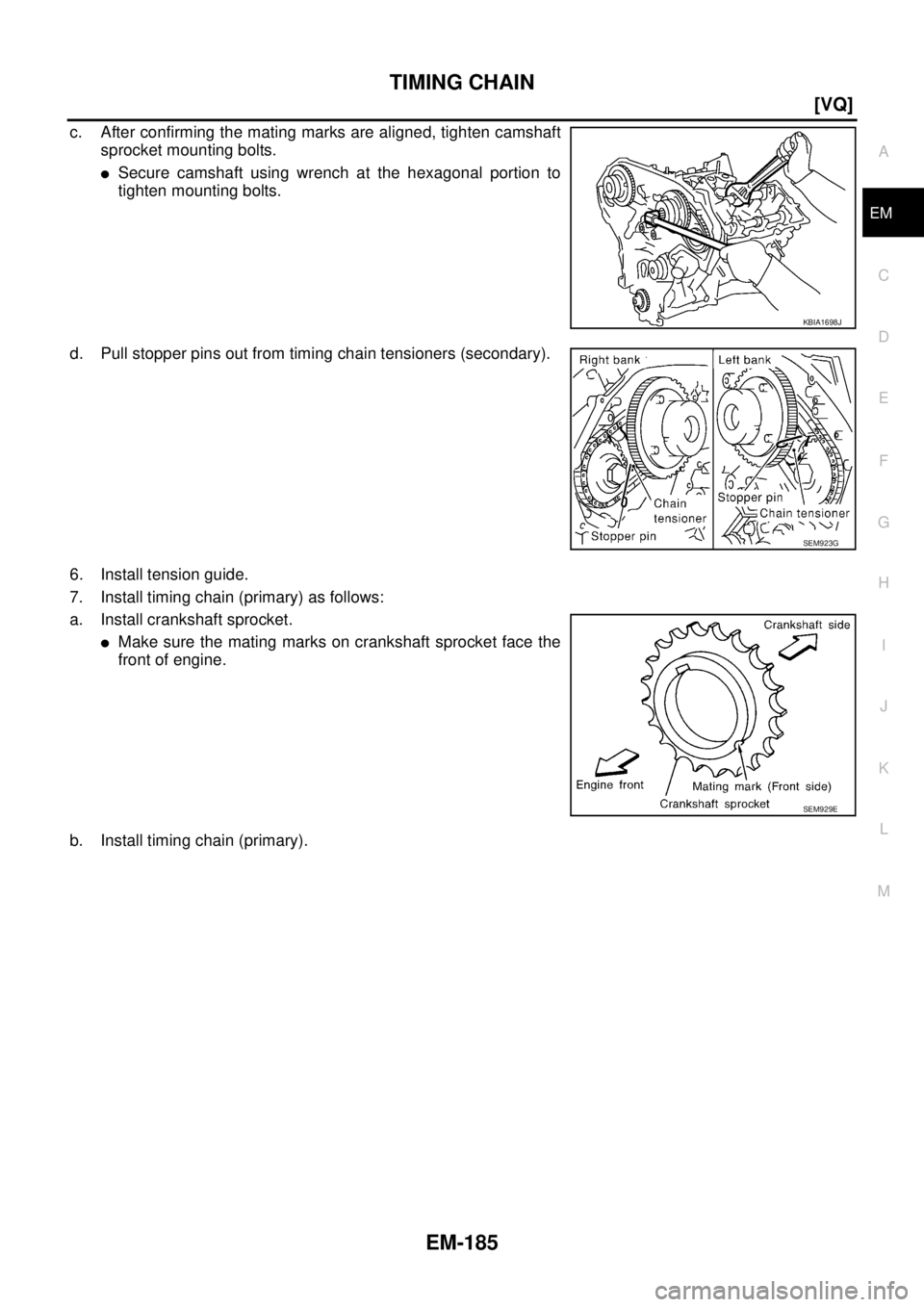
c. After confirming the mating marks are aligned, tighten camshaft
sprocket mounting bolts.
�Secure camshaft using wrench at the hexagonal portion to
tighten mounting bolts.
d. Pull stopper pins out from timing chain tensioners (secondary).
6. Install tension guide.
7. Install timing chain (primary) as follows:
a. Install crankshaft sprocket.
�Make sure the mating marks on crankshaft sprocket face the
front of engine.
b. Install timing chain (primary).
KBIA1698J
SEM923G
SEM929E
Page 2295 of 3502
![NISSAN TEANA 2003 Service Manual TIMING CHAIN
EM-187
[VQ]
C
D
E
F
G
H
I
J
K
L
MA
EM
CAUTION:
Do not overtighten slack guide mounting bolt. It is normal
for a gap to exist under the bolt seat when mounting bolt is
tightened to speci](/manual-img/5/57392/w960_57392-2294.png "NISSAN TEANA 2003 Service Manual TIMING CHAIN
EM-187
[VQ]
C
D
E
F
G
H
I
J
K
L
MA
EM
CAUTION:
Do not overtighten slack guide mounting bolt. It is normal
for a gap to exist under the bolt seat when mounting bolt is
tightened to speci")
TIMING CHAIN
EM-187
[VQ]
C
D
E
F
G
H
I
J
K
L
MA
EM
CAUTION:
Do not overtighten slack guide mounting bolt. It is normal
for a gap to exist under the bolt seat when mounting bolt is
tightened to specification.
9. Install the timing chain tensioner (primary) with the following procedure:
a. Pull plunger stopper tab up (or turn lever downward) so as to
remove plunger stopper tab from the ratchet of plunger.
NOTE:
Plunger stopper tab and lever are synchronized.
b. Push plunger into the inside of tensioner body.
c. Hold plunger in the fully compressed position by engaging
plunger stopper tab with the tip of ratchet.
d. To secure lever, insert stopper pin through hole of lever into ten-
sioner body hole.
�The lever parts and the tab are synchronized. Therefore, the
plunger will be secured under this condition.
NOTE:
Figure shows the example of 1.2 mm (0.047 in) diameter thin screwdriver being used as the stopper pin.
e. Install timing chain tensioner (primary).
�Remove any dirt and foreign materials completely from the
back and the mounting surfaces of timing chain tensioner (pri-
mary).
f. Pull out stopper pin after installing, and then release plunger.
10. Make sure again that the mating marks on each sprocket and each timing chain have not slipped out of
alignment.
11. Install new O-rings on rear timing chain case.
12. Install new front oil seal on front timing chain case.
�Apply new engine oil to both oil seal lip and dust seal lip.
PBIC2633E
PBIC3568E
PBIC3569E
PBIC2548E
Page 2299 of 3502
![NISSAN TEANA 2003 Service Manual TIMING CHAIN
EM-191
[VQ]
C
D
E
F
G
H
I
J
K
L
MA
EM
e. Rotate crankshaft pulley in normal direction (clockwise when viewed from engine front) to confirm it turns
smoothly.
17. For the following opera](/manual-img/5/57392/w960_57392-2298.png "NISSAN TEANA 2003 Service Manual TIMING CHAIN
EM-191
[VQ]
C
D
E
F
G
H
I
J
K
L
MA
EM
e. Rotate crankshaft pulley in normal direction (clockwise when viewed from engine front) to confirm it turns
smoothly.
17. For the following opera")
TIMING CHAIN
EM-191
[VQ]
C
D
E
F
G
H
I
J
K
L
MA
EM
e. Rotate crankshaft pulley in normal direction (clockwise when viewed from engine front) to confirm it turns
smoothly.
17. For the following operations, perform steps in the reverse order of removal.
INSPECTION AFTER INSTALLATION
Inspection for Leaks
The following are procedures for checking fluids leak, lubricates leak and exhaust gases leak.
�Before starting engine, check oil/fluid levels including engine coolant and engine oil. If less than required
quantity, fill to the specified level. Refer to MA-14, "
RECOMMENDED FLUIDS AND LUBRICANTS" .
�Use procedure below to check for fuel leakage.
–Turn ignition switch “ON” (with engine stopped). With fuel pressure applied to fuel piping, check for fuel
leakage at connection points.
–Start engine. With engine speed increased, check again for fuel leakage at connection points.
�Run engine to check for unusual noise and vibration.
NOTE:
If hydraulic pressure inside timing chain tensioner drops after removal/installation, slack in the guide may
generate a pounding noise during and just after engine start. However, this is normal. Noise will stop after
hydraulic pressure rises.
�Warm up engine thoroughly to make sure there is no leakage of fuel, exhaust gases, or any oil/fluids
including engine oil and engine coolant.
�Bleed air from lines and hoses of applicable lines, such as in cooling system.
�After cooling down engine, again check oil/fluid levels including engine oil and engine coolant. Refill to the
specified level, if necessary.
Summary of the inspection items:
* Transmission/transaxle/CVT fluid. power steering fluid, brake fluid, etc.Item Before starting engine Engine running After engine stopped
Engine coolant Level Leakage Level
Engine oil Level Leakage Level
Other oils and fluid* Level Leakage Level
Fuel Leakage Leakage Leakage
Exhaust gases — Leakage —
Page 2300 of 3502
EM-192
[VQ]
CAMSHAFT
CAMSHAFTPFP:13001
Removal and InstallationBBS004W1
REMOVAL
1. Remove engine assembly from vehicle, and separate front suspension member and transaxle from
engine. Refer to EM-223, "
ENGINE ASSEMBLY" .
1.Intake valve timing control solenoid
valve2. Gasket 3. Camshaft bracket (No. 2 to 4)
4. Seal washer 5. Camshaft (EXH) 6. Camshaft (INT)
7. Camshaft bracket (No. 1) 8. Dowel pin 9. Valve lifter
10. O-ring 11. Timing chain tensioner (secondary) 12. Spring
13. Plunger 14. Cylinder head (right bank) 15. Cylinder head (left bank)
16. O-ring 17.Camshaft position sensor (PHASE)
(right bank)18.Camshaft position sensor (PHASE)
(left bank)
PBIC2477E
Page 2301 of 3502
![NISSAN TEANA 2003 Service Manual CAMSHAFT
EM-193
[VQ]
C
D
E
F
G
H
I
J
K
L
MA
EM
2. Install engine sub-attachment with engine stand shaft [SST: KV10117001 and KV10106500] to right side
of cylinder block, then lift engine, and mount](/manual-img/5/57392/w960_57392-2300.png "NISSAN TEANA 2003 Service Manual CAMSHAFT
EM-193
[VQ]
C
D
E
F
G
H
I
J
K
L
MA
EM
2. Install engine sub-attachment with engine stand shaft [SST: KV10117001 and KV10106500] to right side
of cylinder block, then lift engine, and mount")
CAMSHAFT
EM-193
[VQ]
C
D
E
F
G
H
I
J
K
L
MA
EM
2. Install engine sub-attachment with engine stand shaft [SST: KV10117001 and KV10106500] to right side
of cylinder block, then lift engine, and mount it onto engine stand [SST: ST0501S000]. Refer to EM-228,
"CYLINDER BLOCK" .
3. Remove front timing chain case, camshaft sprocket, timing chain and rear timing chain case. Refer to EM-
173, "TIMING CHAIN" .
4. Remove camshaft position sensors (PHASE) (right and left
banks) from cylinder head back side.
CAUTION:
�Handle carefully to avoid dropping and shocks.
�Do not disassemble.
�Do not allow metal powder to adhere to magnetic part at
sensor tip.
�Do not place sensors in a location where they are
exposed to magnetism.
5. Remove intake valve timing control solenoid valves.
�Discard intake valve timing control solenoid valve gaskets and
use new gaskets for installation.
6. Remove camshaft brackets.
�Mark camshafts, camshaft brackets and bolts so they are placed in the same position and direction for
installation.
�Equally loosen camshaft bracket bolts in several steps in the
reverse order as shown in the figure.
7. Remove camshafts.
8. Remove valve lifters.
KBIA1046E
SEM443GA
PBIC2050E
Page 2309 of 3502
![NISSAN TEANA 2003 Service Manual CAMSHAFT
EM-201
[VQ]
C
D
E
F
G
H
I
J
K
L
MA
EM
INSPECTION AFTER INSTALLATION
Inspection of Camshaft Sprocket (INT) Oil Groove
CAUTION:
�Perform this inspection only when DTC P0011 or P0021 are detec](/manual-img/5/57392/w960_57392-2308.png "NISSAN TEANA 2003 Service Manual CAMSHAFT
EM-201
[VQ]
C
D
E
F
G
H
I
J
K
L
MA
EM
INSPECTION AFTER INSTALLATION
Inspection of Camshaft Sprocket (INT) Oil Groove
CAUTION:
�Perform this inspection only when DTC P0011 or P0021 are detec")
CAMSHAFT
EM-201
[VQ]
C
D
E
F
G
H
I
J
K
L
MA
EM
INSPECTION AFTER INSTALLATION
Inspection of Camshaft Sprocket (INT) Oil Groove
CAUTION:
�Perform this inspection only when DTC P0011 or P0021 are detected in self-diagnostic results of
CONSULT-II and it is directed according to inspection procedure of EC section. Refer to EC-427,
"SELF-DIAG RESULTS MODE" .
�Check when engine ins cold so as to prevent burns from any splashing engine oil.
1. Check the engine oil level. Refer to LU-19, "
ENGINE OIL" .
2. Perform the following procedure so as to prevent the engine from being unintentionally started while
checking.
a. Release fuel pressure. Refer to EC-392, "
FUEL PRESSURE RELEASE" .
b. Disconnect ignition coil and injector harness connectors.
3. Remove intake manifold control solenoid valve. Refer to EM-192, "
CAMSHAFT" .
4. Crank the engine, and then make sure that engine oil comes out
from camshaft bracket (No. 1) oil hole. End crank after checking.
WARNING:
Be careful not to touch rotating parts (drive belts, idler pul-
ley, and crankshaft pulley, etc.).
CAUTION:
Engine oil may squirt from intake valve timing control sole-
noid valve installation hole during cranking. Use a shop
cloth to prevent the engine components and the vehicle. Do
not allow engine oil to get on rubber components such as
drive belt or engine mount insulators. Immediately wipe off
any splashed engine oil.
�Clean oil groove between oil strainer and intake valve timing control solenoid valve if engine oil does not
come out from camshaft bracket (No. 1) oil hole. Refer to LU-17, "
LUBRICATION SYSTEM" .
5. Remove components between intake valve timing control solenoid valve and camshaft sprocket (INT),
and then check each oil groove for clogging.
�Clean oil groove if necessary. Refer to LU-17, "LUBRICATION SYSTEM" .
6. After inspection, install removed parts.
Inspection for Leaks
The following are procedures for checking fluids leak, lubricates leak and exhaust gases leak.
�Before starting engine, check oil/fluid levels including engine coolant and engine oil. If less than required
quantity, fill to the specified level. Refer to MA-14, "
RECOMMENDED FLUIDS AND LUBRICANTS" .
�Use procedure below to check for fuel leakage.
–Turn ignition switch “ON” (with engine stopped). With fuel pressure applied to fuel piping, check for fuel
leakage at connection points.
–Start engine. With engine speed increased, check again for fuel leakage at connection points.
�Run engine to check for unusual noise and vibration.
NOTE:
If hydraulic pressure inside timing chain tensioner drops after removal/installation, slack in the guide may
generate a pounding noise during and just after engine start. However, this is normal. Noise will stop after
hydraulic pressure rises.
�Warm up engine thoroughly to make sure there is no leakage of fuel, exhaust gases, or any oil/fluids
including engine oil and engine coolant.
�Bleed air from lines and hoses of applicable lines, such as in cooling system.
�After cooling down engine, again check oil/fluid levels including engine oil and engine coolant. Refill to the
specified level, if necessary.
PBIC2869E
![NISSAN TEANA 2003 Service Manual EM-182
[VQ]
TIMING CHAIN
b. Install new O-rings to cylinder head.
c. Apply liquid gasket with tube presser [SST: WS39930000] to rear timing chain case back side as shown in
the figure.
Use Genuine L](/manual-img/5/57392/w960_57392-2289.png "NISSAN TEANA 2003 Service Manual EM-182
[VQ]
TIMING CHAIN
b. Install new O-rings to cylinder head.
c. Apply liquid gasket with tube presser [SST: WS39930000] to rear timing chain case back side as shown in
the figure.
Use Genuine L")
![NISSAN TEANA 2003 Service Manual EM-192
[VQ]
CAMSHAFT
CAMSHAFTPFP:13001
Removal and InstallationBBS004W1
REMOVAL
1. Remove engine assembly from vehicle, and separate front suspension member and transaxle from
engine. Refer to EM-22](/manual-img/5/57392/w960_57392-2299.png "NISSAN TEANA 2003 Service Manual EM-192
[VQ]
CAMSHAFT
CAMSHAFTPFP:13001
Removal and InstallationBBS004W1
REMOVAL
1. Remove engine assembly from vehicle, and separate front suspension member and transaxle from
engine. Refer to EM-22")