2003 NISSAN ALMERA N16 Pump
[x] Cancel search: PumpPage 8 of 3189

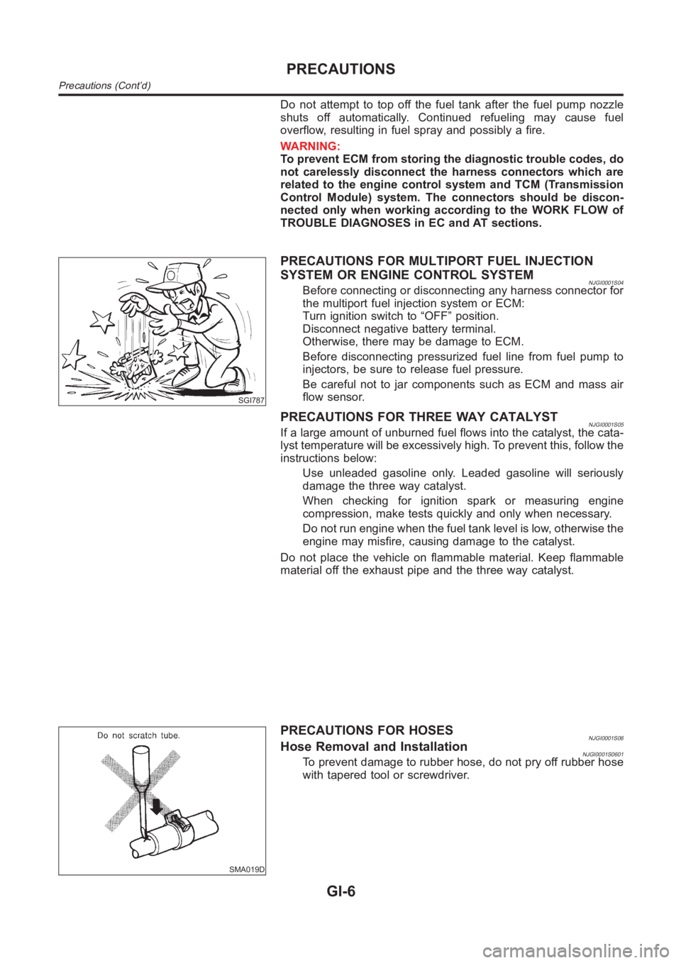
Do not attempt to top off the fuel tank after the fuel pump nozzle
shuts off automatically. Continued refueling may cause fuel
overflow, resulting in fuel spray and possibly a fire.
WARNING:
To prevent ECM from storing the diagnostic trouble codes, do
not carelessly disconnect the harness connectors which are
related to the engine control system and TCM (Transmission
Control Module) system. The connectors should be discon-
nected only when working according to the WORK FLOW of
TROUBLE DIAGNOSES in EC and AT sections.
SGI787
PRECAUTIONS FOR MULTIPORT FUEL INJECTION
SYSTEM OR ENGINE CONTROL SYSTEM
NJGI0001S04Before connecting or disconnecting any harness connector for
the multiport fuel injection system or ECM:
Turn ignition switch to “OFF” position.
Disconnect negative battery terminal.
Otherwise, there may be damage to ECM.
Before disconnecting pressurized fuel line from fuel pump to
injectors, be sure to release fuel pressure.
Be careful not to jar components such as ECM and mass air
flow sensor.
PRECAUTIONS FOR THREE WAY CATALYSTNJGI0001S05If a large amount of unburned fuel flows into the catalyst, the cata-
lyst temperature will be excessively high. To prevent this, follow the
instructions below:
Use unleaded gasoline only. Leaded gasoline will seriously
damage the three way catalyst.
When checking for ignition spark or measuring engine
compression, make tests quickly and only when necessary.
Do not run engine when the fuel tank level is low, otherwise the
engine may misfire, causing damage to the catalyst.
Do not place the vehicle on flammable material. Keep flammable
material off the exhaust pipe and the three way catalyst.
SMA019D
PRECAUTIONS FOR HOSESNJGI0001S06Hose Removal and InstallationNJGI0001S0601To prevent damage to rubber hose, do not pry off rubber hose
with tapered tool or screwdriver.
PRECAUTIONS
Precautions (Cont’d)
GI-6
Page 55 of 3189

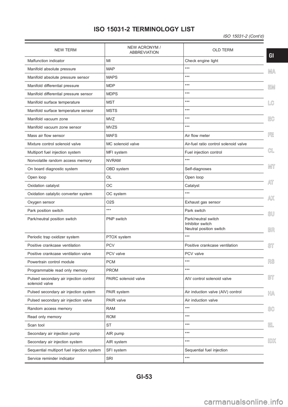
NEW TERMNEW ACRONYM /
ABBREVIATIONOLD TERM
Malfunction indicator MI Check engine light
Manifold absolute pressure MAP ***
Manifold absolute pressure sensor MAPS ***
Manifold differential pressure MDP ***
Manifold differential pressure sensor MDPS ***
Manifold surface temperature MST ***
Manifold surface temperature sensor MSTS ***
Manifold vacuum zone MVZ ***
Manifold vacuum zone sensor MVZS ***
Mass air flow sensor MAFS Air flow meter
Mixture control solenoid valve MC solenoid valve Air-fuel ratio control solenoid valve
Multiport fuel injection system MFI system Fuel injection control
Nonvolatile random access memory NVRAM ***
On board diagnostic system OBD system Self-diagnoses
Open loop OL Open loop
Oxidation catalyst OC Catalyst
Oxidation catalytic converter system OC system ***
Oxygen sensor O2S Exhaust gas sensor
Park position switch *** Park switch
Park/neutral position switch PNP switch Park/neutral switch
Inhibitor switch
Neutral position switch
Periodic trap oxidizer system PTOX system ***
Positive crankcase ventilation PCV Positive crankcase ventilation
Positive crankcase ventilation valve PCV valve PCV valve
Powertrain control module PCM ***
Programmable read only memory PROM ***
Pulsed secondary air injection control
solenoid valvePAIRC solenoid valve AIV control solenoid valve
Pulsed secondary air injection system PAIR system Air induction valve (AIV) control
Pulsed secondary air injection valve PAIR valve Air induction valve
Random access memory RAM ***
Read only memory ROM ***
Scan tool ST ***
Secondary air injection pump AIR pump ***
Secondary air injection system AIR system ***
Sequential multiport fuel injection system SFI system Sequential fuel injection
Service reminder indicator SRI ***
MA
EM
LC
EC
FE
CL
MT
AT
AX
SU
BR
ST
RS
BT
HA
SC
EL
IDX
ISO 15031-2 TERMINOLOGY LIST
ISO 15031-2 (Cont’d)
GI-53
Page 79 of 3189

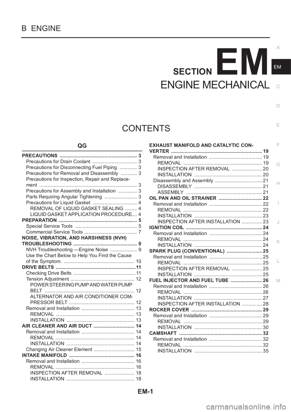
EM-1
ENGINE MECHANICAL
B ENGINE
CONTENTS
C
D
E
F
G
H
I
J
K
L
M
SECTION
A
EM
ENGINE MECHANICAL
QG
PRECAUTIONS .......................................................... 3
Precautions for Drain Coolant .................................. 3
Precautions for Disconnecting Fuel Piping .............. 3
Precautions for Removal and Disassembly ............. 3
Precautions for Inspection, Repair and Replace-
ment ......................................................................... 3
Precautions for Assembly and Installation ............... 3
Parts Requiring Angular Tightening ......................... 3
Precautions for Liquid Gasket .................................. 4
REMOVAL OF LIQUID GASKET SEALING .......... 4
LIQUID GASKET APPLICATION PROCEDURE ..... 4
PREPARATION ........................................................... 5
Special Service Tools ............................................... 5
Commercial Service Tools ........................................ 7
NOISE, VIBRATION, AND HARSHNESS (NVH)
TROUBLESHOOTING ................................................ 9
NVH Troubleshooting —Engine Noise ..................... 9
Use the Chart Below to Help You Find the Cause
of the Symptom. ..................................................... 10
DRIVE BELTS ............................................................11
Checking Drive Belts ............................................... 11
Tension Adjustment ................................................ 12
POWER STEERING PUMP AND WATER PUMP
BELT ................................................................... 12
ALTERNATOR AND AIR CONDITIONER COM-
PRESSOR BELT ................................................. 12
Removal and Installation ........................................ 13
REMOVAL ........................................................... 13
INSTALLATION ................................................... 13
AIR CLEANER AND AIR DUCT ............................... 14
Removal and Installation ........................................ 14
REMOVAL ........................................................... 14
INSTALLATION ................................................... 14
Changing Air Cleaner Element ............................... 15
INTAKE MANIFOLD ................................................. 16
Removal and Installation ........................................ 16
REMOVAL ........................................................... 16
INSPECTION AFTER REMOVAL ....................... 18
INSTALLATION ................................................... 18EXHAUST MANIFOLD AND CATALYTIC CON-
VERTER .................................................................... 19
Removal and Installation ........................................ 19
REMOVAL ........................................................... 19
INSPECTION AFTER REMOVAL ....................... 20
INSTALLATION ................................................... 20
Disassembly and Assembly .................................... 21
DISASSEMBLY ................................................... 21
ASSEMBLY ......................................................... 21
OIL PAN AND OIL STRAINER ..............................
... 22
Removal and Installation ........................................ 22
REMOVAL ........................................................... 22
INSTALLATION ................................................... 23
INSPECTION AFTER INSTALLATION ................ 23
IGNITION COIL ......................................................... 24
Removal and Installation ........................................ 24
REMOVAL ........................................................... 24
INSTALLATION ................................................... 24
SPARK PLUG (CONVENTIONAL) ........................... 25
Removal and Installation ........................................ 25
REMOVAL ........................................................... 25
INSPECTION AFTER REMOVAL ....................... 25
INSTALLATION ................................................... 25
FUEL INJECTOR AND FUEL TUBE ........................ 26
Removal and Installation ........................................ 26
REMOVAL ........................................................... 26
INSTALLATION ................................................... 27
INSPECTION AFTER INSTALLATION ................ 28
ROCKER COVER ..................................................... 29
Removal and Installation ........................................ 29
REMOVAL ........................................................... 29
INSTALLATION ................................................... 30
CAMSHAFT .............................................................. 32
Removal and Installation ........................................ 32
REMOVAL ........................................................... 32
INSTALLATION ................................................... 35
Page 88 of 3189
![NISSAN ALMERA N16 2003 Electronic Repair Manual EM-10
[QG]
NOISE, VIBRATION, AND HARSHNESS (NVH) TROUBLESHOOTING
Use the Chart Below to Help You Find the Cause of the Symptom.
EBS00LPX
1. Locate the area where noise occurs.
2. Confirm the type of n NISSAN ALMERA N16 2003 Electronic Repair Manual EM-10
[QG]
NOISE, VIBRATION, AND HARSHNESS (NVH) TROUBLESHOOTING
Use the Chart Below to Help You Find the Cause of the Symptom.
EBS00LPX
1. Locate the area where noise occurs.
2. Confirm the type of n](/manual-img/5/57350/w960_57350-87.png)
EM-10
[QG]
NOISE, VIBRATION, AND HARSHNESS (NVH) TROUBLESHOOTING
Use the Chart Below to Help You Find the Cause of the Symptom.
EBS00LPX
1. Locate the area where noise occurs.
2. Confirm the type of noise.
3. Specify the operating condition of engine.
4. Check specified noise source.
If necessary, repair or replace these parts.
A: Closely related B: Related C: Sometimes related —: Not relatedLocation
of noiseTy p e o f
noiseOperating condition of engine
Source of
noiseCheck itemRefer-
ence page Before
warm-
upAfter
warm-
upWhen
start-
ingWhen
idlingWhen
racingWhile
driving
Top of
engine
Rocker
cover
Cylinder
headTick in g o r
clickingCA—AB—Tappet
noise
●Valve clearanceEM-42
Rattle C A — A B CCamshaft
bearing
noise
●Camshaft journal
clearance
●Camshaft runoutEM-39EM-39
Crank-
shaft pul-
ley
Cylinder
block
(Side of
engine)
Oil panSlap or
knock—A—B B—Piston pin
noise
●Piston and piston pin
clearance
●Connecting rod
bushing clearanceEM-84EM-87
Slap or
rapA——B B APiston
slap noise
●Piston-to-bore clear-
ance
●Piston ring side
clearance
●Piston ring end gap
●Connecting rod bend
and torsionEM-88
EM-85
EM-86
EM-86
Knock A B C B B BConnect-
ing rod
bearing
noise
●Connecting rod
bushing clearance
(Small end)
●Connecting rod bear-
ing clearance (Big
end)EM-87EM-87
Knock A B — A B CMain
bearing
noise
●Main bearing oil
clearance
●Crankshaft runoutEM-91EM-90
Front of
engine
Timing
chain
coverTapping or
tickingAA—BBBTiming
chain and
chain ten-
sioner
noise●Timing chain cracks
and wear
●Timing chain ten-
sioner operationEM-51EM-47
Front of
engineSqueak-
ing or fizz-
ingAB—B—CDrive belts
(Sticking
or slip-
ping)
●Drive belts deflection
EM-11
CreakingABABABDrive belts
(Slipping)●Idler pulley bearing
operation
Squall
CreakAB—BABWater
pump
noise
●Water pump opera-
tionLC-14
Page 89 of 3189
![NISSAN ALMERA N16 2003 Electronic Repair Manual DRIVE BELTS
EM-11
[QG]
C
D
E
F
G
H
I
J
K
L
MA
EM
DRIVE BELTSPFP:02117
Checking Drive BeltsEBS00LPY
●Before inspecting the engine, make sure the engine has cooled down; wait approximately NISSAN ALMERA N16 2003 Electronic Repair Manual DRIVE BELTS
EM-11
[QG]
C
D
E
F
G
H
I
J
K
L
MA
EM
DRIVE BELTSPFP:02117
Checking Drive BeltsEBS00LPY
●Before inspecting the engine, make sure the engine has cooled down; wait approximately](/manual-img/5/57350/w960_57350-88.png)
DRIVE BELTS
EM-11
[QG]
C
D
E
F
G
H
I
J
K
L
MA
EM
DRIVE BELTSPFP:02117
Checking Drive BeltsEBS00LPY
●Before inspecting the engine, make sure the engine has cooled down; wait approximately 30 minutes
after the engine has been stopped.
●Visually inspect all belts for wear, damage, or cracks on contacting surfaces and edge areas.
●When measuring deflection, apply 98 N (10 kg, 22 lb) at the ▼ marked point.
CAUTION:
When measuring belt tension immediately after belt is installed, first set the tension to the standard.
Then, rotate crankshaft for more than two turns in order to eliminate variance in belt deflection
between the pulleys. Re-measure and adjust the tension to the standard.
PBIC0764E
Deflection adjustment Unit: mm (in)
Used belt
New belt
Limit After adjustment
AlternatorWithout air conditioner compressor 10.2 (0.402)6.5 - 7.0
(0.256 - 0.276)5.5 - 6.1
(0.217 - 0.240)
With air conditioner compressor 8.1 (0.319)5.3 - 5.7
(0.209 - 0.224)4.5 - 5.0
(0.177 - 0.197)
Power steering oil pump 7.1 (0.280)4.4 - 4.9
(0.173 - 0.193)3.9 - 4.4
(0.154 - 0.173)
Applied pushing force 98 N (10 kg, 22 lb)
Page 90 of 3189
![NISSAN ALMERA N16 2003 Electronic Repair Manual EM-12
[QG]
DRIVE BELTS
Tension Adjustment
EBS00LPZ
CAUTION:
●When belt is replaced with a new one, tighten it a little
stronger than current one to accommodate for insufficient
ada NISSAN ALMERA N16 2003 Electronic Repair Manual EM-12
[QG]
DRIVE BELTS
Tension Adjustment
EBS00LPZ
CAUTION:
●When belt is replaced with a new one, tighten it a little
stronger than current one to accommodate for insufficient
ada](/manual-img/5/57350/w960_57350-89.png)
EM-12
[QG]
DRIVE BELTS
Tension Adjustment
EBS00LPZ
CAUTION:
●When belt is replaced with a new one, tighten it a little
stronger than current one to accommodate for insufficient
adaptability with pulley grooves.
●When tension of belt being used exceeds “Retightening
limit”, adjust it to value for “Used belt”.
●When installing belt, make sure that it is correctly engaged with pulley groove.
●Keep oil and water away from belt.
●Do not twist or bend belt excessively.
●When adjusting belt, remove snap retainer from adjusting bolt thread (to prevent the retainer from
becoming pinched or missing).
●After adjustment, be sure to install snap retainer to adjusting bolt thread.
NOTE:
Snap retainer can prevent adjusting bolt from dropping due to vibration during driving.
POWER STEERING PUMP AND WATER PUMP BELT
1. Loosen lock nut (A) and power steering pump mounting nut (B).
2. Turn adjusting bolt (C) to adjust. Refer to EM-11, "
Checking
Drive Belts" .
3. Tighten lock nut (A) and power steering pump mounting nut (B)
in this order.
ALTERNATOR AND AIR CONDITIONER COMPRESSOR BELT
1. Remove RH splash cover (with undercover attached).
2. Loosen lock nut (G).
3. Turn adjusting bolt (H) to adjust.
Refer to EM-11, "
Checking Drive Belts" .
4. Tighten lock nut (G).
Portion Belt tightening method for adjustment
Power steering pump and water pump
beltAdjusting bolt on power steering pump
Alternator and air conditioner compres-
sor beltAdjusting bolt on idler pulley
PBIC0531E
Nut A :
: 16.7 - 23.5 N·m (1.7 - 2.4 kg-m, 13 - 17 ft-lb)
Nut B :
: 26.5 - 36.3 N·m (2.7 - 3.7 kg-m, 20 - 26 ft-lb)
PBIC0532E
Nut G :
: 24.5 - 31.4 N·m (2.5 - 3.2 kg-m, 18 - 23 ft-lb)
Page 101 of 3189
![NISSAN ALMERA N16 2003 Electronic Repair Manual OIL PAN AND OIL STRAINER
EM-23
[QG]
C
D
E
F
G
H
I
J
K
L
MA
EM
7. Insert Tool (Seal cutter) between oil pan and cylinder block.
Slide tool by tapping on the side of the tool with a hammer.
NISSAN ALMERA N16 2003 Electronic Repair Manual OIL PAN AND OIL STRAINER
EM-23
[QG]
C
D
E
F
G
H
I
J
K
L
MA
EM
7. Insert Tool (Seal cutter) between oil pan and cylinder block.
Slide tool by tapping on the side of the tool with a hammer.](/manual-img/5/57350/w960_57350-100.png)
OIL PAN AND OIL STRAINER
EM-23
[QG]
C
D
E
F
G
H
I
J
K
L
MA
EM
7. Insert Tool (Seal cutter) between oil pan and cylinder block.
Slide tool by tapping on the side of the tool with a hammer.
Remove oil pan.
8. Remove oil strainer.
INSTALLATION
1. Install oil strainer.
NOTE:
Gasket and O-ring are not used for sealed area with oil pump.
2. Install oil pan drain plug.
●Referring to “Components”, install drain plug washer.
3. Apply a continuous bead of liquid gasket to position shown in figure.
Use Genuine Liquid Gasket or equivalent.
4. Tighten mounting nuts and bolts in order shown in figure.
●Install mounting nuts and bolts as follows.
5. Install center member.
Refer to ENGINE ASSEMBLY, EM-67, "
Removal and Installa-
tion" .
6. Install remaining parts in the reverse order of removal.
INSPECTION AFTER INSTALLATION
●Check for leakage of engine oil when engine is warmed.
●Pour engine oil or start engine at least 30 minutes after oil pan is installed.
SEM365EA
PBIC0549E
Mounting bolt:
[Shank length under
head 10 mm (0.39 in)]: Nos. 1 - 10, 13, 14
[Shank length under
head 12 mm (0.47 in)]: Nos. 11, 12
SEM072F
Page 125 of 3189
![NISSAN ALMERA N16 2003 Electronic Repair Manual TIMING CHAIN
EM-47
[QG]
C
D
E
F
G
H
I
J
K
L
MA
EM
TIMING CHAINPFP:13028
Removal and InstallationEBS00LQD
CAUTION:
Apply new engine oil to parts marked in illustration before installation.
REMOVAL
1. P NISSAN ALMERA N16 2003 Electronic Repair Manual TIMING CHAIN
EM-47
[QG]
C
D
E
F
G
H
I
J
K
L
MA
EM
TIMING CHAINPFP:13028
Removal and InstallationEBS00LQD
CAUTION:
Apply new engine oil to parts marked in illustration before installation.
REMOVAL
1. P](/manual-img/5/57350/w960_57350-124.png)
TIMING CHAIN
EM-47
[QG]
C
D
E
F
G
H
I
J
K
L
MA
EM
TIMING CHAINPFP:13028
Removal and InstallationEBS00LQD
CAUTION:
Apply new engine oil to parts marked in illustration before installation.
REMOVAL
1. Place vehicle on lift.
PBIC0971E
1. Cylinder head front cover 2. Camshaft sprocket (INT) 3. Washer
4. Camshaft sprocket (EXH) 5. Chain tensioner 6. Chain slack guide
7. O-ring 8. Power steering pump adjusting bar 9. Crankshaft pulley
10. Front oil seal 11. Front cover 12. Chain tension guide
13. Dowel pin 14. Timing chain 15. Oil pump drive spacer
16. Crankshaft sprocket 17. O-ring (with collar) 18. Auxiliary bolt of cylinder head