Page 467 of 3189
![NISSAN ALMERA N16 2003 Electronic Repair Manual DTC P0102, P0103 MAF SENSOR
EC-137
[QG (WITH EURO-OBD)]
C
D
E
F
G
H
I
J
K
L
MA
EC
Specification data are reference values and are measured between each terminal and ground.
CAUTION:
Do not use ECM gro](/manual-img/5/57350/w960_57350-466.png "NISSAN ALMERA N16 2003 Electronic Repair Manual DTC P0102, P0103 MAF SENSOR
EC-137
[QG (WITH EURO-OBD)]
C
D
E
F
G
H
I
J
K
L
MA
EC
Specification data are reference values and are measured between each terminal and ground.
CAUTION:
Do not use ECM gro")
DTC P0102, P0103 MAF SENSOR
EC-137
[QG (WITH EURO-OBD)]
C
D
E
F
G
H
I
J
K
L
MA
EC
Specification data are reference values and are measured between each terminal and ground.
CAUTION:
Do not use ECM ground terminals when measuring input/output voltage. Doing so may result in dam-
age to the ECM's transistor. Use a ground other than ECM terminals, such as the ground.
Diagnostic ProcedureEBS00K52
1.INSPECTION START
Which malfunction (P0102 or P0103) is duplicated?
P0102 or P0103
P0102 >> GO TO 2.
P0103 >> GO TO 3.
2.CHECK INTAKE SYSTEM
Check the following for connection.
●Air duct
●Vacuum hoses
●Intake air passage between air duct to intake manifold
OK or NG
OK >> GO TO 3.
NG >> Reconnect the parts.
3.RETIGHTEN GROUND SCREWS
1. Turn ignition switch “OFF”.
2. Loosen and retighten engine ground screws.
>> GO TO 4.
TERMI-
NAL
NO.WIRE
COLORITEM CONDITION DATA (DC Voltage)
45 RSensor power supply
(Mass air flow sensor)[Ignition switch “ON”]Approximately 5V
50 Y Mass air flow sensor[Engine is running]
●Warm-up condition
●Idle speed1.0 - 1.7V
[Engine is running]
●Warm-up condition
●Engine speed is 2,500 rpm.1.5 - 2.1V
67 BSensor ground
(Mass air flow sensor)[Engine is running]
●Warm-up condition
●Idle speedApproximately 0V
MBIB0095E
Page 828 of 3189
![NISSAN ALMERA N16 2003 Electronic Repair Manual EC-498
[QG (WITHOUT EURO-OBD)]
DTC P0102, P0103 MAF SENSOR
Specification data are reference values and are measured between each terminal and ground.
CAUTION:
Do not use ECM ground terminals when meas](/manual-img/5/57350/w960_57350-827.png "NISSAN ALMERA N16 2003 Electronic Repair Manual EC-498
[QG (WITHOUT EURO-OBD)]
DTC P0102, P0103 MAF SENSOR
Specification data are reference values and are measured between each terminal and ground.
CAUTION:
Do not use ECM ground terminals when meas")
EC-498
[QG (WITHOUT EURO-OBD)]
DTC P0102, P0103 MAF SENSOR
Specification data are reference values and are measured between each terminal and ground.
CAUTION:
Do not use ECM ground terminals when measuring input/output voltage. Doing so may result in dam-
age to the ECM's transistor. Use a ground other than ECM terminals, such as the ground.
Diagnostic ProcedureEBS00KFM
1. INSPECTION START
Which malfunction (P0102 or P0103) is duplicated?
P0102 or P0103
P0102 >> GO TO 2.
P0103 >> GO TO 3.
2. CHECK INTAKE SYSTEM
Check the following for connection.
●Air duct
●Vacuum hoses
●Intake air passage between air duct to intake manifold
OK or NG
OK >> GO TO 3.
NG >> Reconnect the parts.
3. RETIGHTEN GROUND SCREWS
1. Turn ignition switch “OFF”.
2. Loosen and retighten engine ground screws.
>> GO TO 4.
TERMI-
NAL
NO.WIRE
COLORITEM CONDITION DATA (DC Voltage)
45 RSensor power supply
(Mass air flow sensor)[Ignition switch “ON”]Approximately 5V
50 Y Mass air flow sensor[Engine is running]
●Warm-up condition
●Idle speed1.0 - 1.7V
[Engine is running]
●Warm-up condition
●Engine speed is 2,500 rpm.1.5 - 2.1V
67 BSensor ground
(Mass air flow sensor)[Engine is running]
●Warm-up condition
●Idle speedApproximately 0V
MBIB0095E
Page 1132 of 3189
SEF987W
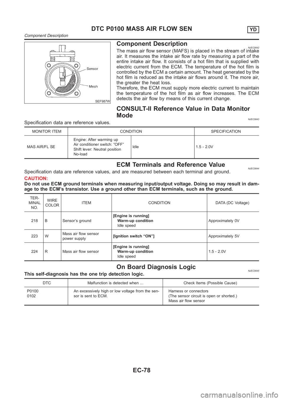
Component DescriptionNJEC0642The mass air flow sensor (MAFS) is placed in the stream of intake
air. It measures the intake air flow rate by measuring a part of the
entire intake air flow. It consists of a hot film that is supplied with
electric current from the ECM. The temperature of the hot film is
controlled by the ECM a certain amount. The heat generated by the
hot film is reduced as the intake air flows around it. The more air,
the greater the heat loss.
Therefore, the ECM must supply more electric current to maintain
the temperature of the hot film as air flow increases. The ECM
detects the air flow by means of this current change.
CONSULT-II Reference Value in Data Monitor
Mode
NJEC0643Specification data are reference values.
MONITOR ITEM CONDITION SPECIFICATION
MAS AIR/FL SEEngine: After warming up
Air conditioner switch: “OFF”
Shift lever: Neutral position
No-loadIdle 1.5 - 2.0V
ECM Terminals and Reference ValueNJEC0644Specification data are reference values, and are measured between each terminal and ground.
CAUTION:
Do not use ECM ground terminals when measuring input/output voltage. Doing so may result in dam-
age to the ECM’s transistor. Use a ground other than ECM terminals, such as the ground.
TER-
MINAL
NO.WIRE
COLORITEM CONDITION DATA (DC Voltage)
218 B Sensor’s ground[Engine is running]
Warm-up condition
Idle speedApproximately 0V
223 WMass air flow sensor
power supply[Ignition switch “ON”]Approximately 5V
224 R Mass air flow sensor[Engine is running]
Warm-up condition
Idle speed1.5 - 2.0V
On Board Diagnosis LogicNJEC0645This self-diagnosis has the one trip detection logic.
DTC Malfunction is detected when ... Check Items (Possible Cause)
P0100
0102An excessively high or low voltage from the sen-
sor is sent to ECM.Harness or connectors
(The sensor circuit is open or shorted.)
Mass air flow sensor
DTC P0100 MASS AIR FLOW SENYD
Component Description
EC-78