2003 NISSAN ALMERA N16 ATC
[x] Cancel search: ATCPage 1 of 3189
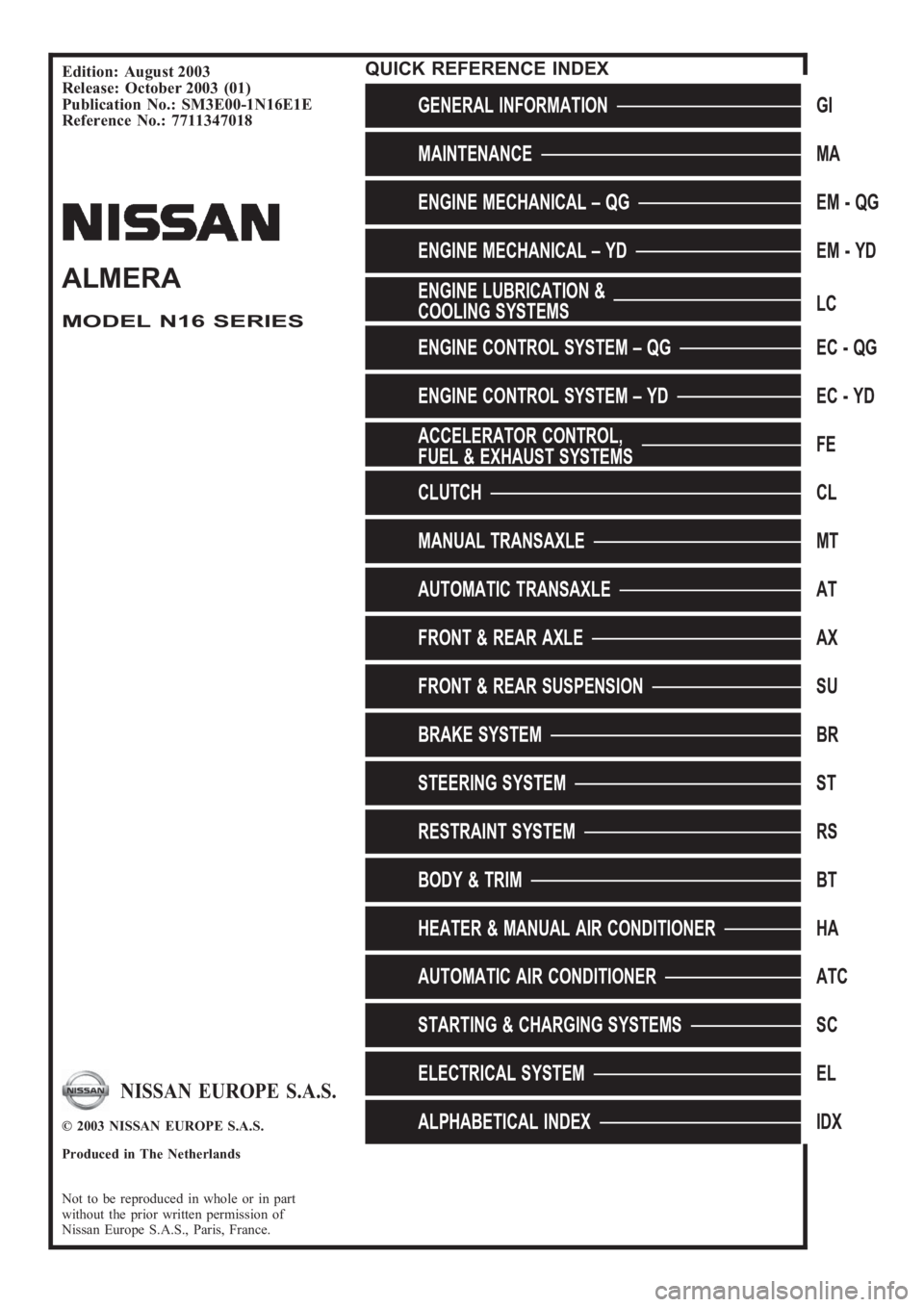
Edition: August 2003
Release: October 2003 (01)
Publication No.: SM3E00-1N16E1E
Reference No.: 7711347018
GENERAL INFORMATIONGI
MAINTENANCEMA
ENGINE MECHANICAL – QGEM-QG
ENGINE MECHANICAL – YDEM-YD
ENGINE LUBRICATION &
COOLING SYSTEMSLC
ENGINE CONTROL SYSTEM – QGEC - QG
ENGINE CONTROL SYSTEM – YDEC - YD
ACCELERATOR CONTROL,
FUEL & EXHAUST SYSTEMSFE
CLUTCHCL
MANUAL TRANSAXLEMT
AUTOMATIC TRANSAXLEAT
FRONT & REAR AXLEAX
FRONT & REAR SUSPENSIONSU
BRAKE SYSTEMBR
STEERING SYSTEMST
RESTRAINT SYSTEMRS
BODY & TRIMBT
HEATER & MANUAL AIR CONDITIONERHA
AUTOMATIC AIR CONDITIONERATC
STARTING & CHARGING SYSTEMSSC
ELECTRICAL SYSTEMEL
ALPHABETICAL INDEXIDX
ALMERA
MODEL N16 SERIES
NISSAN EUROPE S.A.S.
© 2003 NISSAN EUROPE S.A.S.
Produced in The Netherlands
Not to be reproduced in whole or in part
without the prior written permission of
Nissan Europe S.A.S., Paris, France.
QUICK REFERENCE INDEX
Page 7 of 3189
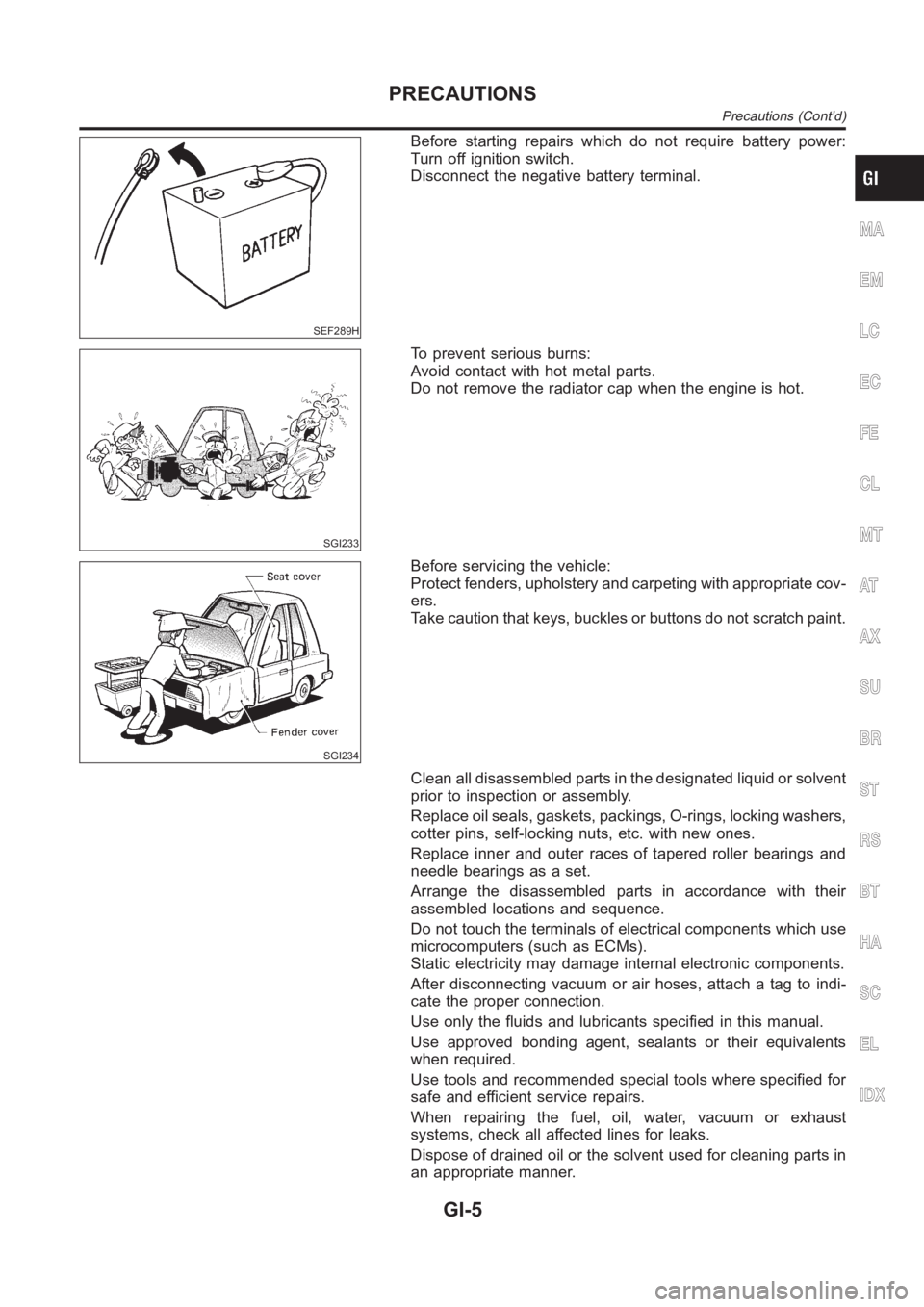
SEF289H
Before starting repairs which do not require battery power:
Turn off ignition switch.
Disconnect the negative battery terminal.
SGI233
To prevent serious burns:
Avoid contact with hot metal parts.
Do not remove the radiator cap when the engine is hot.
SGI234
Before servicing the vehicle:
Protect fenders, upholstery and carpeting with appropriate cov-
ers.
Take caution that keys, buckles or buttons do not scratch paint.
Clean all disassembled parts in the designated liquid or solvent
prior to inspection or assembly.
Replace oil seals, gaskets, packings, O-rings, locking washers,
cotter pins, self-locking nuts, etc. with new ones.
Replace inner and outer races of tapered roller bearings and
needle bearings as a set.
Arrange the disassembled parts in accordance with their
assembled locations and sequence.
Do not touch the terminals of electrical components which use
microcomputers (such as ECMs).
Static electricity may damage internal electronic components.
After disconnecting vacuum or air hoses, attach a tag to indi-
cate the proper connection.
Use only the fluids and lubricants specified in this manual.
Use approved bonding agent, sealants or their equivalents
when required.
Use tools and recommended special tools where specified for
safe and efficient service repairs.
When repairing the fuel, oil, water, vacuum or exhaust
systems, check all affected lines for leaks.
Dispose of drained oil or the solvent used for cleaning parts in
an appropriate manner.
MA
EM
LC
EC
FE
CL
MT
AT
AX
SU
BR
ST
RS
BT
HA
SC
EL
IDX
PRECAUTIONS
Precautions (Cont’d)
GI-5
Page 11 of 3189
fuels in your diesel engine. The use of those can cause
engine damage.
Do not use summer fuel at temperatures below −7°C
(20°F). The cold temperatures will cause wax to form in the
fuel. As a result, it may prevent the engine from running
smoothly.
Do not add gasoline or other alternate fuels to diesel fuel.
PRECAUTIONS FOR AIR CONDITIONINGNJGI0001S09Use an approved refrigerant recovery unit any time the air condi-
tioning system must be discharged. Refer to HA-77 (Manual) or
ATC-132 (Auto), “HFC-134a (R-134a) Service Procedure” for spe-
cific instructions.
MA
EM
LC
EC
FE
CL
MT
AT
AX
SU
BR
ST
RS
BT
HA
SC
EL
IDX
PRECAUTIONS
Precautions (Cont’d)
GI-9
Page 12 of 3189
NJGI0002
The captionsWARNINGandCAUTIONwarm you of steps that must be followed to prevent personal injury
and/or damage to some part of the vehicle.
WARNINGindicates the possibility of personal injury if instructions are not followed.
CAUTIONindicates the possibility of component damage if instructions are not followed.
BOLD TYPED STATEMENTSexceptWARNINGandCAUTIONgive you helpful information.
ALPHABETICAL INDEXis provided at the end of this manual so that you can rapidly find the item and
page you are searching for.
A QUICK REFERENCE INDEX, a black tab (e.g.
) is provided on the first page. You can quickly find
the first page of each section by matching it to the section’s black tab.
THE CONTENTSare listed on the first page of each section.
THE TITLEis indicated on the upper portion of each page and shows the part or system.
THE PAGE NUMBERof each section consists of two letters which designate the particular section and a
number (e.g. “BR-5”).
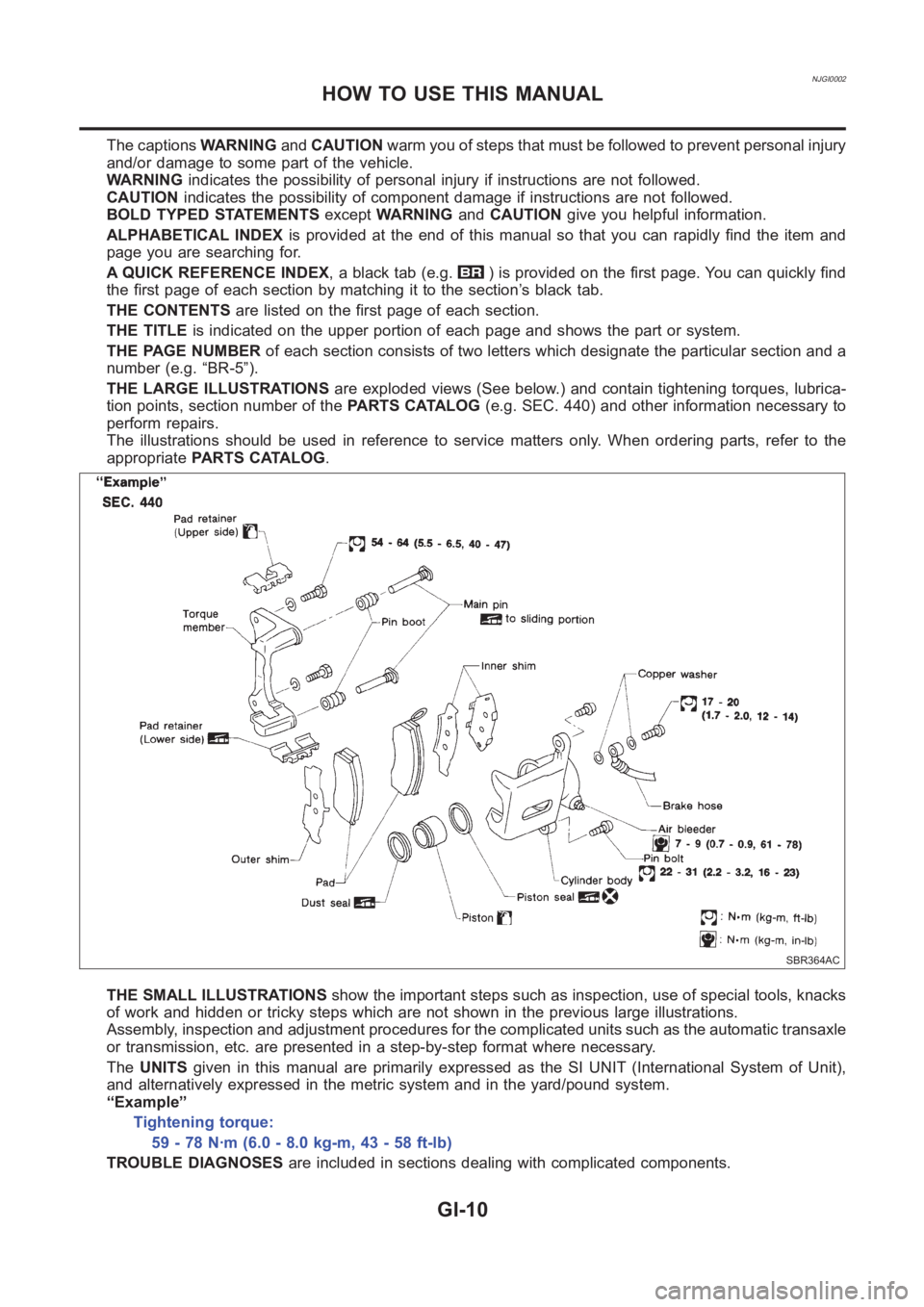
THE LARGE ILLUSTRATIONSare exploded views (See below.) and contain tightening torques, lubrica-
tion points, section number of thePARTS CATALOG(e.g. SEC. 440) and other information necessary to
perform repairs.
The illustrations should be used in reference to service matters only. When ordering parts, refer to the
appropriatePARTS CATALOG.
SBR364AC
THE SMALL ILLUSTRATIONSshow the important steps such as inspection, use of special tools, knacks
of work and hidden or tricky steps which are not shown in the previous large illustrations.
Assembly, inspection and adjustment procedures for the complicated units such as the automatic transaxle
or transmission, etc. are presented in a step-by-step format where necessary.
TheUNITSgiven in this manual are primarily expressed as the SI UNIT (InternationalSystem of Unit),
and alternatively expressed in the metric system and in the yard/pound system.
“Example”
Tightening torque:
59 - 78 N·m (6.0 - 8.0 kg-m, 43 - 58 ft-lb)
TROUBLE DIAGNOSESare included in sections dealing with complicated components.
HOW TO USE THIS MANUAL
GI-10
Page 16 of 3189
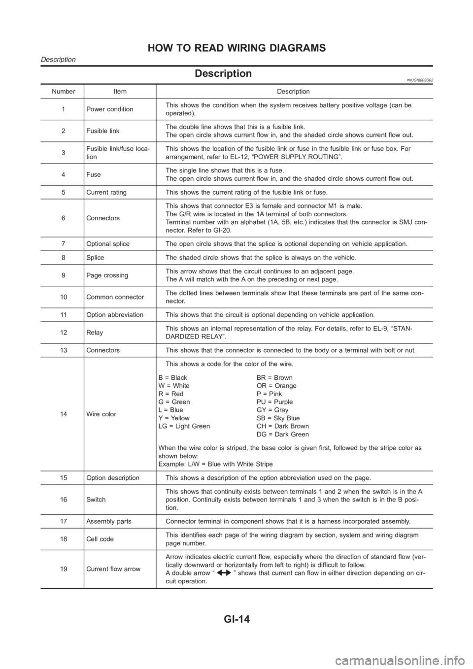
Description=NJGI0003S02
Number Item Description
1 Power conditionThis shows the condition when the system receives battery positive voltage (can be
operated).
2 Fusible linkThe double line shows that this is a fusible link.
The open circle shows current flow in, and the shaded circle shows current flow out.
3Fusible link/fuse loca-
tionThis shows the location of the fusible link or fuse in the fusible link or fusebox.For
arrangement, refer to EL-12, “POWER SUPPLY ROUTING”.
4FuseThe single line shows that this is a fuse.
The open circle shows current flow in, and the shaded circle shows current flow out.
5 Current rating This shows the current rating of the fusible link or fuse.
6 ConnectorsThis shows that connector E3 is female and connector M1 is male.
The G/R wire is located in the 1A terminal of both connectors.
Terminal number with an alphabet (1A, 5B, etc.) indicates that the connector is SMJ con-
nector. Refer to GI-20.
7 Optional splice The open circle shows that the splice is optional depending on vehicle application.
8 Splice The shaded circle shows that the splice is always on the vehicle.
9 Page crossingThis arrow shows that the circuit continues to an adjacent page.
The A will match with the A on the preceding or next page.
10 Common connectorThe dotted lines between terminals show that these terminals are part of thesamecon-
nector.
11 Option abbreviation This shows that the circuit is optional depending on vehicle application.
12 RelayThis shows an internal representation of the relay. For details, refer to EL-9, “STAN-
DARDIZED RELAY”.
13 Connectors This shows that the connector is connected to the body or a terminal with bolt or nut.
14 Wire colorThis shows a code for the color of the wire.
B=Black
W = White
R = Red
G = Green
L = Blue
Y = Yellow
LG = Light GreenBR = Brown
OR = Orange
P = Pink
PU = Purple
GY = Gray
SB = Sky Blue
CH = Dark Brown
DG=DarkGreen
When the wire color is striped, the base color is given first, followed by the stripe color as
shown below:
Example: L/W = Blue with White Stripe
15 Option description This shows a description of the option abbreviationused on the page.
16 SwitchThis shows that continuity exists between terminals 1 and 2 when the switchis in the A
position. Continuity exists between terminals 1 and 3 when the switch is inthe B posi-
tion.
17 Assembly parts Connector terminal in component shows that it is a harness incorporated assembly.
18 Cell codeThis identifies each page of the wiring diagram by section, system and wiring diagram
page number.
19 Current flow arrowArrow indicates electric current flow, especially where the direction ofstandard flow (ver-
tically downward or horizontally from left to right) is difficult to follow.
A double arrow “
” shows that current can flow in either direction depending on cir-
cuit operation.
HOW TO READ WIRING DIAGRAMS
Description
GI-14
Page 17 of 3189
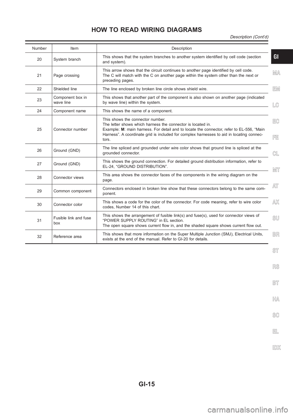
Number Item Description
20 System branchThis shows that the system branches to another system identified by cell code (section
and system).
21 Page crossingThis arrow shows that the circuit continues to another page identified by cell code.
The C will match with the C on another page within the system other than the next or
preceding pages.
22 Shielded line The line enclosed by broken line circle shows shield wire.
23Component box in
wave lineThis shows that another part of the component is also shown on another page (indicated
by wave line) within the system.
24 Component name This shows the name of a component.
25 Connector numberThis shows the connector number.
The letter shows which harness the connector is located in.
Example:M: main harness. For detail and to locate the connector, refer to EL-556, “Main
Harness”. A coordinate grid is included for complex harnesses to aid in locating connec-
tors.
26 Ground (GND)The line spliced and grounded under wire color shows that ground line is spliced at the
grounded connector.
27 Ground (GND)This shows the ground connection. For detailed ground distribution information, refer to
EL-24, “GROUND DISTRIBUTION”.
28 Connector viewsThis area shows the connector faces of the components in the wiring diagramon the
page.
29 Common componentConnectors enclosed in broken line show that these connectors belong to thesamecom-
ponent.
30 Connector colorThis shows a code for the color of the connector. For code meaning, refer to wire color
codes, Number 14 of this chart.
31Fusible link and fuse
boxThis shows the arrangement of fusible link(s) and fuse(s), used for connector views of
“POWER SUPPLY ROUTING” in EL section.
The open square shows current flow in, and the shaded square shows current flow out.
32 Reference areaThis shows that more information on the Super Multiple Junction (SMJ), Electrical Units,
exists at the end of the manual. Refer to GI-20 for details.
MA
EM
LC
EC
FE
CL
MT
AT
AX
SU
BR
ST
RS
BT
HA
SC
EL
IDX
HOW TO READ WIRING DIAGRAMS
Description (Cont’d)
GI-15
Page 38 of 3189
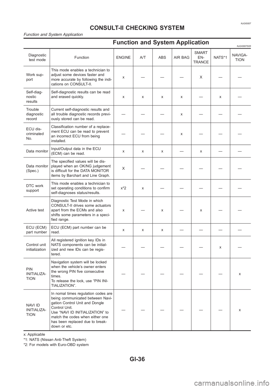
NJGI0007
Function and System ApplicationNJGI0007S05
Diagnostic
test modeFunction ENGINE A/T ABS AIR BAGSMART
EN-
TRANCENATS*1NAVIGA-
TION
Work sup-
portThis mode enables a technician to
adjust some devices faster and
more accurate by following the indi-
cations on CONSULT-II.x ———X——
Self-diag-
nostic
resultsSelf-diagnostic results can be read
anderasedquickly. x x x x—x—
Trouble
diagnostic
recordCurrent self-diagnostic results and
all trouble diagnostic records previ-
ously stored can be read.——— x ———
ECU dis-
criminated
No.Classification number of a replace-
ment ECU can be read to prevent
an incorrect ECU from being
installed.——— x ———
Data monitorInput/Output data in the ECU
(ECM) can be read.x x x—x——
Data monitor
(Spec.)The specified values will be dis-
played when an OK/NG judgement
is difficult for the DATA MONITOR
items by Barchart and Line Graph.X ——————
DTC work
supportThis mode enables a technician to
set operating conditions to confirm
self-diagnoses status/results.x*2x —————
Active testDiagnostic Test Mode in which
CONSULT-II drives some actuators
apart from the ECMs and also
shifts some parameters in a speci-
fied range.x—x—x——
ECU (ECM)
part numberECU (ECM) part number can be
read.x x x ————
Control unit
initializationAll registered ignition key IDs in
NATS components can be initial-
ized and new IDs can be regis-
tered.————— x —
PIN
INITIALIZA-
TIONNavigation system will be locked
when the vehicle’s owner enters
the wrong PIN five consecutive
times.
To release the lock, use “PIN INI-
TIALIZATION”.—————— x
NAVI ID
INITIALIZA-
TIONIn nomal times regulation codes are
being communicated between Navi-
gation Control Unit and Dongle
Control Unit.
Use “NAVI ID INITIALIZATION” to
match the codes when either one
has been replaced due to break-
down or etc.—————— x
x: Applicable
*1: NATS (Nissan Anti-Theft System)
*2: For models with Euro-OBD system
CONSULT-II CHECKING SYSTEM
Function and System Application
GI-36
Page 41 of 3189
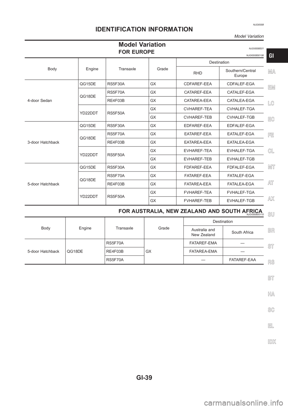
NJGI0008
Model VariationNJGI0008S01FOR EUROPENJGI0008S0106
Body Engine Transaxle GradeDestination
RHDSouthern/Central
Europe
4-door SedanQG15DE RS5F30A GX CDFAREF-EEA CDFALEF-EGA
QG18DERS5F70A GX CATAREF-EEA CATALEF-EGA
RE4F03B GX CATAREA-EEA CATALEA-EGA
YD22DDT RS5F50AGX CVHAREF-TEA CVHALEF-TGA
GX CVHAREF-TEB CVHALEF-TGB
3-door HatchbackQG15DE RS5F30A GX EDFAREF-EEA EDFALEF-EGA
QG18DERS5F70A GX EATAREF-EEA EATALEF-EGA
RE4F03B GX EATAREA-EEA EATALEA-EGA
YD22DDT RS5F50AGX EVHAREF-TEA EVHALEF-TGA
GX EVHAREF-TEB EVHALEF-TGB
5-door HatchbackQG15DE RS5F30A GX FDFAREF-EEA FDFALEF-EGA
QG18DERS5F70A GX FATAREF-EEA FATALEF-EGA
RE4F03B GX FATAREA-EEA FATALEA-EGA
YD22DDT RS5F50AGX FVHAREF-TEA FVHALEF-TGA
GX FVHAREF-TEB EVHALEF-TGB
FOR AUSTRALIA, NEW ZEALAND AND SOUTH AFRICANJGI0008S0110
Body Engine Transaxle GradeDestination
Australia and
New ZealandSouth Africa
5-door Hatchback QG18DERS5F70A
GXFATAREF-EMA —
RE4F03B FATAREA-EMA —
RS5F70A — FATAREF-EAA
MA
EM
LC
EC
FE
CL
MT
AT
AX
SU
BR
ST
RS
BT
HA
SC
EL
IDX
IDENTIFICATION INFORMATION
Model Variation
GI-39