Page 2389 of 3189
Wiring Diagram — H/AIM —NJEL0424
YEL673D
GI
MA
EM
LC
EC
FE
CL
MT
AT
AX
SU
BR
ST
RS
BT
HA
SC
IDX
HEADLAMP — HEADLAMP AIMING CONTROL —
Wiring Diagram — H/AIM —
EL-53
Page 2390 of 3189
YEL674D
HEADLAMP — HEADLAMP AIMING CONTROL —
Wiring Diagram — H/AIM — (Cont’d)
EL-54
Page 2504 of 3189
Wiring Diagram — HLC —NJEL0459
YEL455D
HEADLAMP WASHER
Wiring Diagram — HLC —
EL-168
Page 2505 of 3189
NEL802
Washer Tube LayoutNJEL0376
GI
MA
EM
LC
EC
FE
CL
MT
AT
AX
SU
BR
ST
RS
BT
HA
SC
IDX
HEADLAMP WASHER
Washer Tube Layout
EL-169
Page 2704 of 3189

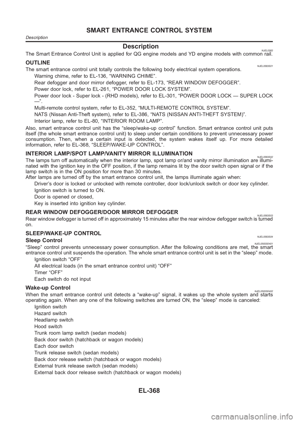
DescriptionNJEL0583The Smart Entrance Control Unit is applied for QG engine models and YD engine models with common rail.
OUTLINENJEL0583S01The smart entrance control unit totally controls the following body electrical system operations.
Warning chime, refer to EL-136, “WARNING CHIME”.
Rear defogger and door mirror defogger, refer to EL-173, “REAR WINDOW DEFOGGER”.
Power door lock, refer to EL-261, “POWER DOOR LOCK SYSTEM”.
Power door lock - Super lock - (RHD models), refer to EL-301, “POWER DOOR LOCK — SUPER LOCK
—”.
Multi-remote control system, refer to EL-352, “MULTI-REMOTE CONTROL SYSTEM”.
NATS (Nissan Anti-Theft system), refer to EL-386, “NATS (NISSAN ANTI-THEFT SYSTEM)”.
Interior lamp, refer to EL-80, “INTERIOR ROOM LAMP”.
Also, smart entrance control unit has the “sleep/wake-up control” function. Smart entrance control unit puts
itself (the whole smart entrance control unit) to sleep under certain conditions to prevent unnecessary power
consumption. Then, when a certain input is detected, the system wakes itself up. For more detailed
information, refer to EL-368, “SLEEP/WAKE-UP CONTROL”.
INTERIOR LAMP/SPOT LAMP/VANITY MIRROR ILLUMINATIONNJEL0583S02The lamps turn off automatically when the interior lamp, spot lamp or/and vanity mirror illumination are illumi-
nated with the ignition key in the OFF position, if the lamp remains lit by the door switch open signal or if the
lamp switch is in the ON position for more than 30 minutes.
After lamps are turned off by the smart entrance control unit, the lamps illuminate again when:
Driver’s door is locked or unlocked with remote controller, door lock/unlock switch or door key cylinder.
Ignition switch is turned to ON.
Door is opened or closed,
Key is inserted into ignition key cylinder.
REAR WINDOW DEFOGGER/DOOR MIRROR DEFOGGERNJEL0583S03Rear window defogger is turned off in approximately 15 minutes after the rear window defogger switch is turned
on.
SLEEP/WAKE-UP CONTROLNJEL0583S04Sleep ControlNJEL0583S0401“Sleep” control prevents unnecessary power consumption. After the following conditions are met, the smart
entrance control unit suspends the operation. The whole smart entrance control unit is set in the “sleep” mode.
Ignition switch “OFF”
All electrical loads (in the smart entrance control unit) “OFF”
Timer “OFF”
Each switch do not input
Wake-up ControlNJEL0583S0402When the smart entrance control unit detects a “wake-up” signal, it wakes up the whole system and starts
operating again. When any one of the following switches are turned ON, the “sleep” mode is canceled:
Ignition switch
Hazard switch
Headlamp switch
Hood switch
Trunk room lamp switch (sedan models)
Back door switch (hatchback or wagon models)
Each door switch
Trunk release switch (sedan models)
Back door release switch (hatchback or wagon models)
External trunk release switch (sedan models)
External back door release switch (hatchback or wagon models)
SMART ENTRANCE CONTROL SYSTEM
Description
EL-368
Page 2706 of 3189

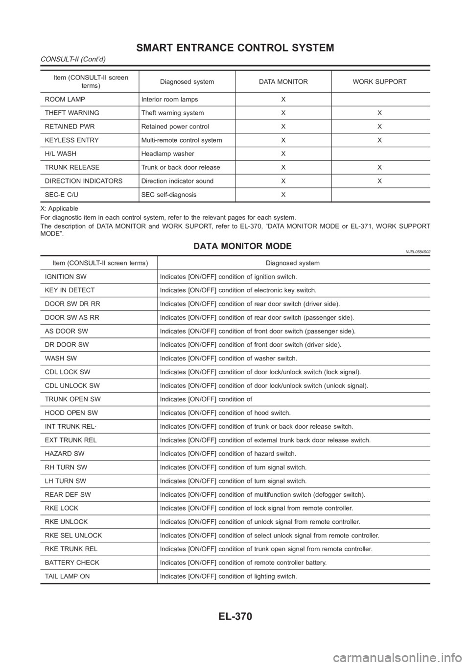
Item (CONSULT-II screen
terms)Diagnosed system DATA MONITOR WORK SUPPORT
ROOM LAMP Interior room lamps X
THEFT WARNING Theft warning system X X
RETAINED PWR Retained power control X X
KEYLESS ENTRY Multi-remote control system X X
H/L WASH Headlamp washer X
TRUNK RELEASE Trunk or back door release X X
DIRECTION INDICATORS Direction indicator sound X X
SEC-E C/U SEC self-diagnosis X
X: Applicable
For diagnostic item in each control system, refer to the relevant pages foreach system.
The description of DATA MONITOR and WORK SUPORT, refer to EL-370, “DATA MONITOR MODE or EL-371, WORK SUPPORT
MODE”.
DATA MONITOR MODENJEL0584S02
Item (CONSULT-II screen terms) Diagnosed system
IGNITION SW Indicates [ON/OFF] condition of ignition switch.
KEY IN DETECT Indicates [ON/OFF] condition of electronic key switch.
DOOR SW DR RR Indicates [ON/OFF] condition of rear door switch (driver side).
DOOR SW AS RR Indicates [ON/OFF] condition of rear door switch (passenger side).
AS DOOR SW Indicates [ON/OFF] condition of front door switch (passenger side).
DR DOOR SW Indicates [ON/OFF] condition of front door switch (driver side).
WASH SW Indicates [ON/OFF] condition of washer switch.
CDL LOCK SW Indicates [ON/OFF] condition of door lock/unlock switch (locksignal).
CDL UNLOCK SW Indicates [ON/OFF] condition of door lock/unlock switch (unlock signal).
TRUNK OPEN SW Indicates [ON/OFF] condition of
HOOD OPEN SW Indicates [ON/OFF] condition of hood switch.
INT TRUNK REL· Indicates [ON/OFF] condition of trunk or back door release switch.
EXT TRUNK REL Indicates [ON/OFF] condition of external trunk back door release switch.
HAZARD SW Indicates [ON/OFF] condition of hazard switch.
RH TURN SW Indicates [ON/OFF] condition of turn signal switch.
LH TURN SW Indicates [ON/OFF] condition of turn signal switch.
REAR DEF SW Indicates [ON/OFF] condition of multifunction switch (defogger switch).
RKE LOCK Indicates [ON/OFF] condition of lock signal from remote controller.
RKE UNLOCK Indicates [ON/OFF] condition of unlock signal from remote controller.
RKE SEL UNLOCK Indicates [ON/OFF] condition of select unlock signal from remote controller.
RKE TRUNK REL Indicates [ON/OFF] condition of trunk open signal from remote controller.
BATTERY CHECK Indicates [ON/OFF] condition of remote controller battery.
TAIL LAMP ON Indicates [ON/OFF] condition of lighting switch.
SMART ENTRANCE CONTROL SYSTEM
CONSULT-II (Cont’d)
EL-370
Page 2713 of 3189
![NISSAN ALMERA N16 2003 Electronic Repair Manual Terminal
No.Wire
colorConnections Operated condition Voltage (Approximate values)
24 BRWasher switch
(Headlamp washer switch)[Head lamp switch 1st or 2nd posi-
tion]
Washer switch OFF,ON12V,0V
25 G/OR NISSAN ALMERA N16 2003 Electronic Repair Manual Terminal
No.Wire
colorConnections Operated condition Voltage (Approximate values)
24 BRWasher switch
(Headlamp washer switch)[Head lamp switch 1st or 2nd posi-
tion]
Washer switch OFF,ON12V,0V
25 G/OR](/manual-img/5/57350/w960_57350-2712.png)
Terminal
No.Wire
colorConnections Operated condition Voltage (Approximate values)
24 BRWasher switch
(Headlamp washer switch)[Head lamp switch 1st or 2nd posi-
tion]
Washer switch OFF,ON12V,0V
25 G/ORCombination switch
(Turn signal switch)Turn signal switch:
Neutral,Left turn position12V,0V
26 L/BCombination switch
(Turn signal switch)Turn signal switch:
Neutral,Right turn position12V,0V
27 Y/BVehicle security horn relay
(RHD models)When theft warning system:
Armed,Disarmed0V,12V
28 R/Y Interior room lampWhen interior lamp is operated using
remote controller (Lamp switch in
“DOOR” position)12V,0V
29 Y/G Ignition key switch Ignition key is in “ON” position 12V
30 G/R Hazard switch Hazard switch: OFF,ON 12V,0V
31 W Rear window defogger relay[Ignition switch “ON”]
Rear window defogger switch:
OFF,ON12V,0V
32 LG/B Cooling fan relay[Ignition switch“ ON”]
Cooling fan: Operating,Not operat-
ing0V,12V
33 LG/R Cooling fan relay[Ignition switch “ON”]
Cooling fan: Operating,Not operat-
ing0V,12V
34 L/Y Security indicator Ignition switch ON,OFF 12V,0V
39 BR/WRear door switch
(Passenger side)Rear door LH or RH: Open,Closed 0V,12V
41 L Air conditioner relay[Engine is running]
Air conditioner switch: ON,
OFF12V,0V
43 R/WFront door switch
(Driver side)Front door (Driver side):
Open,Closed12V,0V
44 R/WFront door switch
(Passenger side)Front door (Passenger side):
Open,Closed0V,12V
45 R/YRear door switch
(Driver side)Rear door LH or RH: Open,Closed 0V,12V
49 W/L Power source — 12V
50 GPower door super lock actuator
(Rear)Remote controller door lock switch:
Free,Press0V,12V
51 L/R Driver door lock actuatorDoor lock & unlock switch:
Free,Lock0V,12V
52 W/R Door lock actuatorsDoor lock & unlock switch:
Free,Unlock0V,12V
53 B Ground — 0V
54 R/B Door lock actuatorsDoor lock & unlock switch:
Free,Unlock0V,12V
55 W/BPower door super lock actuator
(Front)Remote controller door lock switch:
Free,Unlock0V,12V
56 R/B Power source — 12V
GI
MA
EM
LC
EC
FE
CL
MT
AT
AX
SU
BR
ST
RS
BT
HA
SC
IDX
SMART ENTRANCE CONTROL SYSTEM
Smart Entrance Control Unit Inspection Table (Cont’d)
EL-377
Page 2714 of 3189

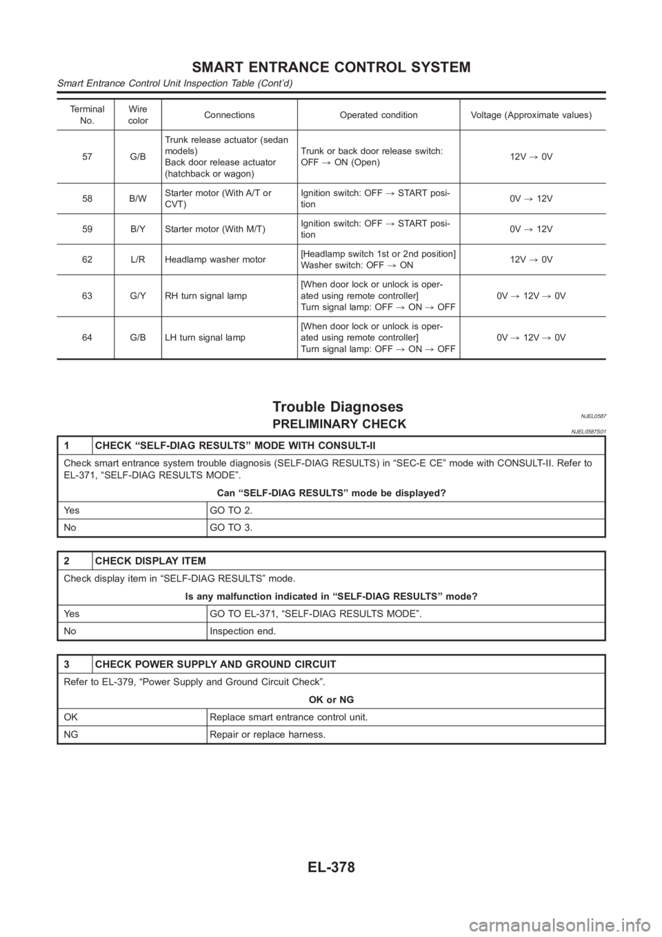
Terminal
No.Wire
colorConnections Operated condition Voltage (Approximate values)
57 G/BTrunk release actuator (sedan
models)
Back door release actuator
(hatchback or wagon)Trunk or back door release switch:
OFF,ON (Open)12V,0V
58 B/WStarter motor (With A/T or
CVT)Ignition switch: OFF,START posi-
tion0V,12V
59 B/Y Starter motor (With M/T)Ignition switch: OFF,START posi-
tion0V,12V
62 L/R Headlamp washer motor[Headlamp switch 1st or 2nd position]
Washer switch: OFF,ON12V,0V
63 G/Y RH turn signal lamp[When door lock or unlock is oper-
ated using remote controller]
Turn signal lamp: OFF,ON,OFF0V,12V,0V
64 G/B LH turn signal lamp[When door lock or unlock is oper-
ated using remote controller]
Turn signal lamp: OFF,ON,OFF0V,12V,0V
Trouble DiagnosesNJEL0587PRELIMINARY CHECKNJEL0587S01
1 CHECK “SELF-DIAG RESULTS” MODE WITH CONSULT-II
Check smart entrance system trouble diagnosis (SELF-DIAG RESULTS) in “SEC-E CE” mode with CONSULT-II. Refer to
EL-371, “SELF-DIAG RESULTS MODE”.
Can “SELF-DIAG RESULTS” mode be displayed?
Ye s G O T O 2 .
No GO TO 3.
2 CHECK DISPLAY ITEM
Check display item in “SELF-DIAG RESULTS” mode.
Is any malfunction indicated in “SELF-DIAG RESULTS” mode?
Yes GO TO EL-371, “SELF-DIAG RESULTS MODE”.
No Inspection end.
3 CHECK POWER SUPPLY AND GROUND CIRCUIT
Refer to EL-379, “Power Supply and Ground Circuit Check”.
OK or NG
OK Replace smart entrance control unit.
NG Repair or replace harness.
SMART ENTRANCE CONTROL SYSTEM
Smart Entrance Control Unit Inspection Table (Cont’d)
EL-378