2003 NISSAN ALMERA N16 electrical system
[x] Cancel search: electrical systemPage 796 of 3189
![NISSAN ALMERA N16 2003 Electronic Repair Manual EC-466
[QG (WITHOUT EURO-OBD)]
TROUBLE DIAGNOSIS
ENGINE CONTROL COMPONENT PARTS/CONTROL SYSTEMS APPLICATION
X: Applicable
*1: This item includes 1st trip DTCs.
*2: This mode includes 1st trip freeze f NISSAN ALMERA N16 2003 Electronic Repair Manual EC-466
[QG (WITHOUT EURO-OBD)]
TROUBLE DIAGNOSIS
ENGINE CONTROL COMPONENT PARTS/CONTROL SYSTEMS APPLICATION
X: Applicable
*1: This item includes 1st trip DTCs.
*2: This mode includes 1st trip freeze f](/manual-img/5/57350/w960_57350-795.png)
EC-466
[QG (WITHOUT EURO-OBD)]
TROUBLE DIAGNOSIS
ENGINE CONTROL COMPONENT PARTS/CONTROL SYSTEMS APPLICATION
X: Applicable
*1: This item includes 1st trip DTCs.
*2: This mode includes 1st trip freeze frame data or freeze frame data. The items appear on CONSULT-II screen in freeze frame data
mode only if a 1st trip DTC or DTC is detected. For details, refer to EC-468
.
CONSULT-II INSPECTION PROCEDURE
1. Turn ignition switch OFF.
ItemDIAGNOSTIC TEST MODE
WORK
SUPPORTSELF-DIAGNOSTIC
RESULTS
DATA
MONI-
TORDATA
MONI-
TOR
(SPEC)ACTIVE
TEST DTC*1FREEZE
FRAME
DATA
*2
ENGINE CONTROL COMPONENT PARTS
INPUT
Crankshaft position sensor (POS)××××
Camshaft position sensor (PHASE)×××
Mass air flow sensor×××
Engine coolant temperature sensor×××××
Heated oxygen sensor 1×××
Heated oxygen sensor 2×××
Vehicle speed signal×××
Accelerator pedal position sensor×××
Throttle position sensor×××
Intake air temperature sensor××
Knock sensor×
Refrigerant pressure sensor××
Closed throttle position switch (accelerator
pedal position sensor signal)××
Air conditioner switch××
Park/neutral position (PNP) switch××
Stop lamp switch×××
Power steering pressure sensor××
Battery voltage××
Electrical load signal××
ENGINE CONTROL COMPONENT PARTS
OUTPUT
Injectors×× ×
Power transistor (Ignition timing)×× ×
Throttle control motor relay×××
Throttle control motor×
EVAP canister purge volume control sole-
noid valve×× ×
Air conditioner relay××
Fuel pump relay××××
Cooling fan relay××××
Heated oxygen sensor 1 heater××
Heated oxygen sensor 2 heater××
Intake valve timing control solenoid valve×× ×
Calculated load value×××
Page 811 of 3189
![NISSAN ALMERA N16 2003 Electronic Repair Manual TROUBLE DIAGNOSIS - SPECIFICATION VALUE
EC-481
[QG (WITHOUT EURO-OBD)]
C
D
E
F
G
H
I
J
K
L
MA
EC
TROUBLE DIAGNOSIS - SPECIFICATION VALUEPFP:00031
DescriptionEBS00KF3
The specification (SP) value indic NISSAN ALMERA N16 2003 Electronic Repair Manual TROUBLE DIAGNOSIS - SPECIFICATION VALUE
EC-481
[QG (WITHOUT EURO-OBD)]
C
D
E
F
G
H
I
J
K
L
MA
EC
TROUBLE DIAGNOSIS - SPECIFICATION VALUEPFP:00031
DescriptionEBS00KF3
The specification (SP) value indic](/manual-img/5/57350/w960_57350-810.png)
TROUBLE DIAGNOSIS - SPECIFICATION VALUE
EC-481
[QG (WITHOUT EURO-OBD)]
C
D
E
F
G
H
I
J
K
L
MA
EC
TROUBLE DIAGNOSIS - SPECIFICATION VALUEPFP:00031
DescriptionEBS00KF3
The specification (SP) value indicates the tolerance of the value that is displayed in “DATA MONITOR (SPEC)”
mode of CONSULT-II during normal operation of the Engine Control System. When the value in “DATA MONI-
TOR (SPEC)” mode is within the SP value, the Engine Control System is confirmed OK. When the value in
“DATA MONITOR (SPEC)” mode is NOT within the SP value, the Engine Control System may have one or
more malfunctions.
The SP value is used to detect malfunctions that may affect the Engine Control System, but will not light the
MI.
The SP value will be displayed for the following three items:
●B/FUEL SCHDL (The fuel injection pulse width programmed into ECM prior to any learned on board cor-
rection)
●A/F ALPHA-B1 (The mean value of air-fuel ratio feedback correction factor per cycle)
●MAS A/F SE-B1 (The signal voltage of the mass air flow sensor)
Testing ConditionEBS00KF4
●Vehicle driven distance: More than 5,000 km (3,017 miles)
●Barometric pressure: 98.3 - 104.3 kPa (0.983 - 1.043 bar, 1.003 - 1.064 kg/cm2 , 14.25 - 15.12 psi)
●Atmospheric temperature: 20 - 30°C (68 - 86°F)
●Engine coolant temperature: 75 - 95°C (167 - 203°F)
●Transmission: Warmed-up*1
●Electrical load: Not applied*2
●Engine speed: Idle
*1: For A/T models, after the engine is warmed up to normal operating temperature, drive vehicle until “FLUID
TEMP SE” (A/T fluid temperature sensor signal) indicates more than 60°C (140°F).
For M/T models, after the engine is warmed up to normal operating temperature, drive vehicle for 5 minutes.
*2: Rear window defogger switch, air conditioner switch, lighting switch are “OFF”. Steering wheel is straight
ahead.
Inspection ProcedureEBS00KF5
NOTE:
Perform “DATA MONITOR (SPEC)” mode in maximum scale display.
1. Perform EC-443, "
Basic Inspection" .
2. Confirm that the testing conditions indicated above are met.
3. Select “B/FUEL SCHDL”, “A/F ALPHA-B1” and “MAS A/F SE-
B1” in “DATA MONITOR (SPEC)” mode with CONSULT-II.
4. Make sure that monitor items are within the SP value.
5. If NG, go to EC-482, "
Diagnostic Procedure" .
SEF601Z
Page 831 of 3189
![NISSAN ALMERA N16 2003 Electronic Repair Manual DTC P0117, P0118 ECT SENSOR
EC-501
[QG (WITHOUT EURO-OBD)]
C
D
E
F
G
H
I
J
K
L
MA
EC
DTC P0117, P0118 ECT SENSORPFP:22630
Component DescriptionEBS00KFP
The engine coolant temperature sensor is used to NISSAN ALMERA N16 2003 Electronic Repair Manual DTC P0117, P0118 ECT SENSOR
EC-501
[QG (WITHOUT EURO-OBD)]
C
D
E
F
G
H
I
J
K
L
MA
EC
DTC P0117, P0118 ECT SENSORPFP:22630
Component DescriptionEBS00KFP
The engine coolant temperature sensor is used to](/manual-img/5/57350/w960_57350-830.png)
DTC P0117, P0118 ECT SENSOR
EC-501
[QG (WITHOUT EURO-OBD)]
C
D
E
F
G
H
I
J
K
L
MA
EC
DTC P0117, P0118 ECT SENSORPFP:22630
Component DescriptionEBS00KFP
The engine coolant temperature sensor is used to detect the engine
coolant temperature. The sensor modifies a voltage signal from the
ECM. The modified signal returns to the ECM as the engine coolant
temperature input. The sensor uses a thermistor which is sensitive to
the change in temperature. The electrical resistance of the ther-
mistor decreases as temperature increases.
*: These data are reference values and are measured between ECM terminal 72
(Engine coolant temperature sensor) and ground.
CAUTION:
Do not use ECM ground terminals when measuring input/output voltage. Doing so may result in dam-
age to the ECM's transistor. Use a ground other than ECM terminals, such as the ground.
On Board Diagnosis LogicEBS00KFQ
These self-diagnoses have the one trip detection logic.
FAIL-SAFE MODE
When this malfunction is detected, the ECM enters fail-safe mode and the MI lights up.
SEF594K
Engine coolant
temperature°C (°F)Voltage* V Resistance kΩ
−10 (14) 4.4 7.0 - 11.4
20 (68) 3.5 2.1 - 2.9
50 (122) 2.2 0.68 - 1.00
90 (194) 0.9 0.236 - 0.260
SEF012P
DTC No. Trouble Diagnosis Name DTC Detecting Condition Possible Cause
P0117
0117Engine coolant temperature
sensor circuit low inputAn excessively low voltage from the sensor is
sent to ECM.
●Harness or connectors
(The sensor circuit is open or shorted.)
●Engine coolant temperature sensor P0118
0118Engine coolant temperature
sensor circuit high inputAn excessively high voltage from the sensor is
sent to ECM.
Detected items Engine operating condition in fail-safe mode
Engine coolant temper-
ature sensor circuitEngine coolant temperature will be determined by ECM based on the time after turning ignition switch “ON”
or “START”.
CONSULT-II displays the engine coolant temperature decided by ECM.
ConditionEngine coolant temperature decided
(CONSULT-II display)
Just as ignition switch is turned ON or Start 40°C (104°F)
More than approx. 4 minutes after ignition ON or
Start80°C (176°F)
Except as shown above40 - 80°C (104 - 176°F)
(Depends on the time)
When the fail-safe system for engine coolant temperature sensor is activated, the cooling fan operates
while engine is running.
Page 1043 of 3189
![NISSAN ALMERA N16 2003 Electronic Repair Manual ELECTRICAL LOAD SIGNAL
EC-713
[QG (WITHOUT EURO-OBD)]
C
D
E
F
G
H
I
J
K
L
MA
EC
3.CHECK LOAD SIGNAL CIRCUIT OVERALL FUNCTION-II
Without CONSULT-II
Check voltage between ECM terminal 84 and ground NISSAN ALMERA N16 2003 Electronic Repair Manual ELECTRICAL LOAD SIGNAL
EC-713
[QG (WITHOUT EURO-OBD)]
C
D
E
F
G
H
I
J
K
L
MA
EC
3.CHECK LOAD SIGNAL CIRCUIT OVERALL FUNCTION-II
Without CONSULT-II
Check voltage between ECM terminal 84 and ground](/manual-img/5/57350/w960_57350-1042.png)
ELECTRICAL LOAD SIGNAL
EC-713
[QG (WITHOUT EURO-OBD)]
C
D
E
F
G
H
I
J
K
L
MA
EC
3.CHECK LOAD SIGNAL CIRCUIT OVERALL FUNCTION-II
Without CONSULT-II
Check voltage between ECM terminal 84 and ground under the fol-
lowing conditions.
OK or NG
OK >>INSPECTION END
NG >> GO TO 5.
4.CHECK REAR WINDOW DEFOGGER SYSTEM
Refer to EL-173.
>>INSPECTION END
5.CHECK HEADLAMP FUNCTION
1. Turn lighting switch “ON” at 2nd position.
2. Check that headlamps are illuminated.
OK or NG
OK >> GO TO 6.
NG >> Refer to EL-42 or EL-46.
6.CHECK HEADLAMP INPUT SIGNAL CIRCUIT FOR OPEN AND SHORT
WITHOUT DAYTIME LIGHT SYSTEM
1. Turn ignition switch “OFF”.
2. Disconnect ECM harness connector.
3. Disconnect lighting switch harness connector.
4. Check harness continuity between ECM terminal 84 and lighting switch terminal 10.
Refer to Wiring Diagram.
5. Also check harness for short to ground and short to power.
WITH DAYTIME LIGHT SYSTEM
1. Turn ignition switch “OFF”.
2. Disconnect ECM harness connector.
3. Disconnect daytime light relay.
4. Check harness continuity between ECM terminal 84 and daytime light relay terminal 3.
Refer to Wiring Diagram.
5. Also check harness for short to ground and short to power.
OK or NG
OK >> GO TO 8.
NG >> GO TO 7.
Condition Voltage
Lighting switch “ON” at 2nd position Battery voltage
Lighting switch “OFF” Approximately 0V
MBIB0158E
Continuity should exist.
Continuity should exist.
Page 1060 of 3189

Supplemental Restraint System (SRS) “AIR
BAG” and “SEAT BELT PRE-TENSIONER”
NJEC0601The Supplemental Restraint System such as “AIR BAG” and “SEAT BELT PRE-TENSIONER” used along with
a seat belt, helps to reduce the risk or severity of injury to the driver and front passenger for certain types of
collision. The SRS system composition which is available to NISSAN MODEL N16 is as follows (The compo-
sition varies according to the destination and optional equipment.):
For a frontal collision
The Supplemental Restraint System consists of driver air bag module (located in the center of the steer-
ing wheel), front passenger air bag module (located on the instrument panel on passenger side), front seat
belt pre-tensioners, a diagnosis sensor unit, warning lamp, wiring harness and spiral cable.
For a side collision
The Supplemental Restraint System consists of front side air bag module (located in the outer side of front
seat), side air bag (satellite) sensor, diagnosis sensor unit (one of components of air bags for a frontal
collision), wiring harness, warning lamp (one of components of air bags for a frontal collision).
Information necessary to service the system safely is included in theRS sectionof this Service Manual.
WARNING:
To avoid rendering the SRS inoperative, which could increase the risk of personal injury or death
in the event of a collision which would result in air bag inflation, all maintenance should be per-
formed by an authorized NISSAN dealer.
Improper maintenance, including incorrect removal and installation of the SRS, can lead to per-
sonal injury caused by unintentional activation of the system. For removalofSpiralCableandAir
Bag Module, see the RS section.
Do not use electrical test equipment on any circuit related to the SRS unless instructed to in this
Service Manual. SRS wiring harness can be identified by yellow and/or orange harness connector.
PRECAUTIONSYD
Supplemental Restraint System (SRS) “AIR BAG” and “SEAT BELT PRE-TENSIONER”
EC-6
Page 1102 of 3189

Basic InspectionNJEC0632Precaution:
Perform Basic Inspection without electrical or mechanical
loads applied;
Headlamp switch is OFF,
On vehicles equipped with daytime light systems, set
lighting switch to the 1st position to light only small
lamps.
Air conditioner switch is OFF,
Rear defogger switch is OFF,
Steering wheel is in the straight-ahead position, etc.
1 INSPECTION START
1. Check service records for any recent repairs that may indicate a relatedincident.
2. Check the current need for scheduled maintenance, especially for fuel filter and air cleaner filter. Refer to MA-4, “Peri-
odic Maintenance”.
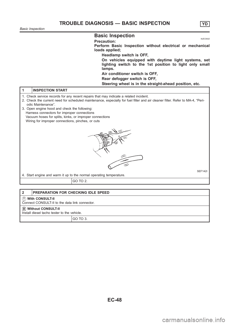
3. Open engine hood and check the following:
Harness connectors for improper connections
Vacuum hoses for splits, kinks, or improper connections
Wiring for improper connections, pinches, or cuts
SEF142I
4. Start engine and warm it up to the normal operating temperature.
GO TO 2.
2 PREPARATION FOR CHECKING IDLE SPEED
With CONSULT-II
Connect CONSULT-II to the data link connector.
Without CONSULT-II
Install diesel tacho tester to the vehicle.
GO TO 3.
TROUBLE DIAGNOSIS — BASIC INSPECTIONYD
Basic Inspection
EC-48
Page 1251 of 3189

DescriptionNJEC0764SYSTEM DESCRIPTIONNJEC0764S01
Sensor Input Signal to ECM ECM Function Actuator
Electronic controlled fuel injection pump Fuel injection signal
EGR volume con-
trolEGR volume control
valve Crankshaft position sensor (TDC) Engine speed
Vehicle speed sensor Vehicle speed
Engine coolant temperature sensor Engine coolant temperature
Ignition switch Start signal
Accelerator position sensor Accelerator position
Mass air flow sensor Amount of intake air
Air conditioner switch Air conditioner operation
Electrical load Electrical load signal
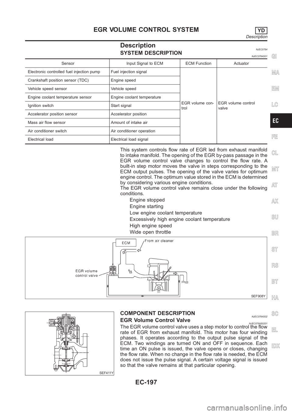
This system controls flow rate of EGR led from exhaust manifold
to intake manifold. The opening of the EGR by-pass passage in the
EGR volume control valve changes to control the flow rate. A
built-in step motor moves the valve in steps corresponding to the
ECM output pulses. The opening of the valve varies for optimum
engine control. The optimum value stored in the ECM is determined
by considering various engine conditions.
The EGR volume control valve remains close under the following
conditions.
Engine stopped
Engine starting
Low engine coolant temperature
Excessively high engine coolant temperature
High engine speed
Wide open throttle
SEF908Y
SEF411Y
COMPONENT DESCRIPTIONNJEC0764S02EGR Volume Control ValveNJEC0764S0201The EGR volume control valve uses a step motor to control the flow
rate of EGR from exhaust manifold. This motor has four winding
phases. It operates according to the output pulse signal of the
ECM. Two windings are turned ON and OFF in sequence. Each
time an ON pulse is issued, the valve opens or closes, changing
the flow rate. When no change in the flow rate is needed, the ECM
does not issue the pulse signal. A certain voltage signal is issued
so that the valve remains at that particular opening.
GI
MA
EM
LC
FE
CL
MT
AT
AX
SU
BR
ST
RS
BT
HA
SC
EL
IDX
EGR VOLUME CONTROL SYSTEMYD
Description
EC-197
Page 1271 of 3189

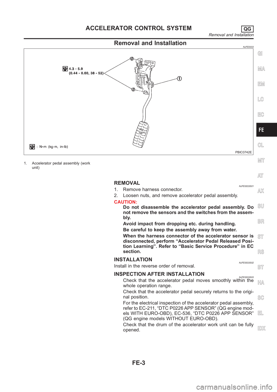
Removal and InstallationNJFE0033
PBIC0742E
1. Accelerator pedal assembly (work
unit)
REMOVALNJFE0033S011. Remove harness connector.
2. Loosen nuts, and remove accelerator pedal assembly.
CAUTION:
Do not disassemble the accelerator pedal assembly. Do
not remove the sensors and the switches from the assem-
bly.
Avoid impact from dropping etc. during handling.
Be careful to keep the assembly away from water.
When the harness connector of the accelerator sensor is
disconnected, perform “Accelerator Pedal Released Posi-
tion Learning”. Refer to “Basic Service Procedure” in EC
section.
INSTALLATIONNJFE0033S02Install in the reverse order of removal.
INSPECTION AFTER INSTALLATIONNJFE0033S03Check that the accelerator pedal moves smoothly within the
whole operation range.
Check that the accelerator pedal securely returns to the origi-
nal position.
For the electrical inspection of the accelerator pedal assembly,
refer to EC-211, “DTC P0226 APP SENSOR” (QG engine mod-
els WITH EURO-OBD), EC-536, “DTC P0226 APP SENSOR”
(QG engine models WITHOUT EURO-OBD).
Check that the drum of the accelerator work unit can be fully
opened.
GI
MA
EM
LC
EC
CL
MT
AT
AX
SU
BR
ST
RS
BT
HA
SC
EL
IDX
ACCELERATOR CONTROL SYSTEMQG
Removal and Installation
FE-3