Page 296 of 3189
Water Pump
REMOVAL AND INSTALLATIONNJLC0018
SEM858F
SEM859F
CAUTION:
When removing water pump assembly, be careful not to
get coolant on drive belt.
Water pump cannot be disassembled and should be
replaced as a unit.
After installing water pump, and check for leaks using
radiator cap tester.
1. Drain engine coolant.
Refer to LC-17, “Changing Engine Coolant”.
2. Remove drive belts and idler pulley.
3. Loosen water pump pulley bolts.
4. Remove water pump pulley.
5. Remove front right wheel.
6. Remove front right undercover and front right fender protector.
7. Remove water pump bolts.
8. Remove water pump.
9. Reinstall parts in reverse order of removal.
SEM860F
INSPECTIONNJLC0019Check body assembly and vane for rust or corrosion.
Check for rough operation due to excessive end play.
ENGINE COOLING SYSTEMQG
Water Pump
LC-14
Page 321 of 3189
JLC294B
REMOVALNJLC00561. Remove the undercover, splash cover (right), and accessory
belt.
2. Drain engine coolant. Refer to LC-43, “Changing Engine Cool-
ant”.
3. Support the bottom of the oil pan with a floor jack etc., and
remove the right engine mount bracket (front side of the
engine).
4. Remove the water pump pulley.
Loosen the pulley bolts after fixing the pulley using a screw-
driver etc.
5. Remove engine mount brackets.
6. Remove the water pump.
INSPECTIONNJLC0057Check for rust and contamination adhering to the water pump
and vane.
Turn the pump shaft by hand, and check that the pump turns
smoothly without looseness.
INSTALLATIONNJLC0058Install the parts in the reverse order of removal.
Install the water pump pulley with the front mark (painted white,
used to prevent errors during assembly) facing the front of the
engine. Refer to the figure above.
GI
MA
EM
EC
FE
CL
MT
AT
AX
SU
BR
ST
RS
BT
HA
SC
EL
IDX
ENGINE COOLING SYSTEMYD
Water Pump (Cont’d)
LC-39
Page 1080 of 3189

JEF351Y
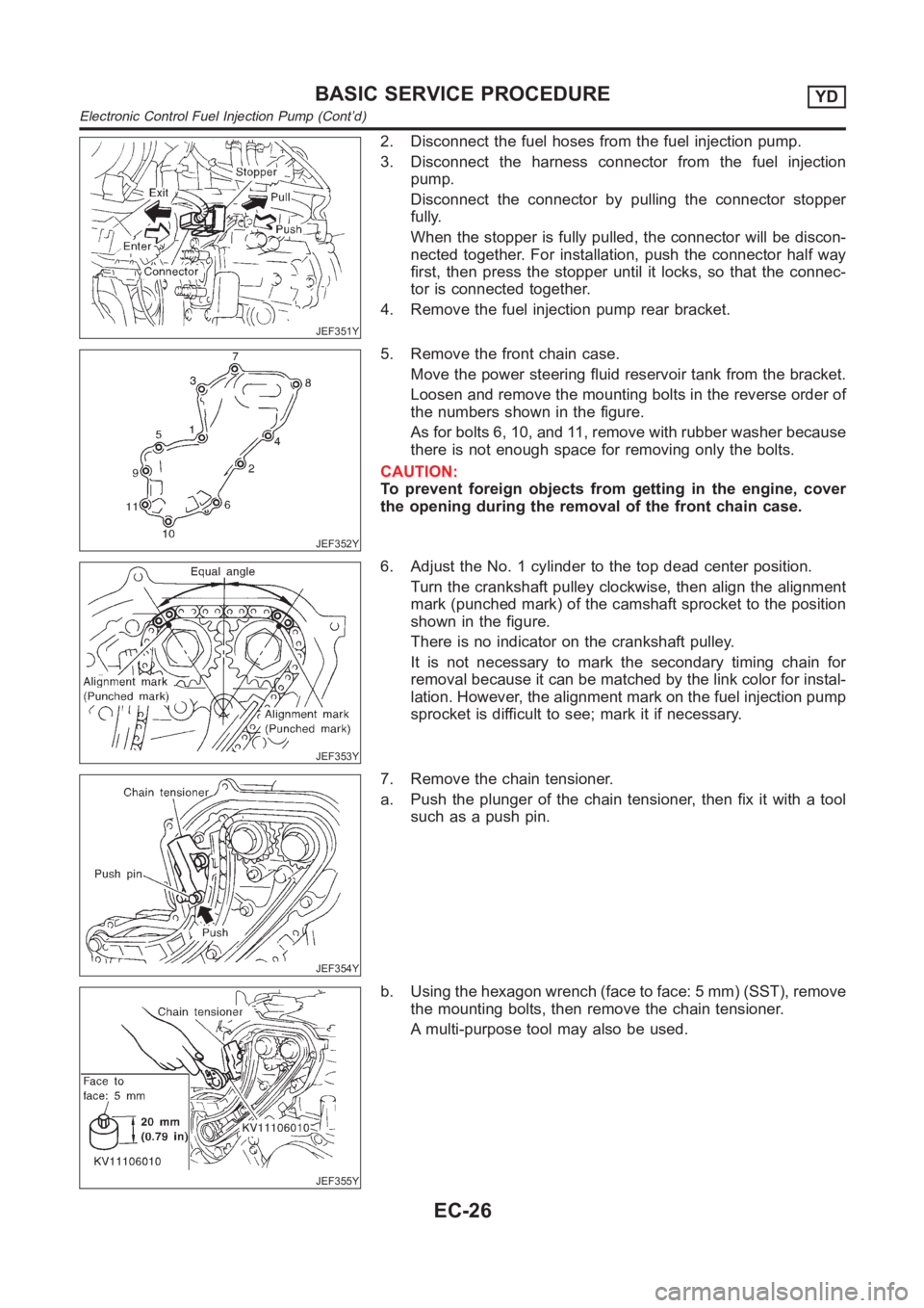
2. Disconnect the fuel hoses from the fuel injection pump.
3. Disconnect the harness connector from the fuel injection
pump.
Disconnect the connector by pulling the connector stopper
fully.
When the stopper is fully pulled, the connector will be discon-
nected together. For installation, push the connector half way
first, then press the stopper until it locks, so that the connec-
tor is connected together.
4. Remove the fuel injection pump rear bracket.
JEF352Y
5. Remove the front chain case.
Move the power steering fluid reservoir tank from the bracket.
Loosen and remove the mounting bolts in the reverse order of
the numbers shown in the figure.
As for bolts 6, 10, and 11, remove with rubber washer because
there is not enough space for removing only the bolts.
CAUTION:
To prevent foreign objects from getting in the engine, cover
the opening during the removal of the front chain case.
JEF353Y
6. Adjust the No. 1 cylinder to the top dead center position.
Turn the crankshaft pulley clockwise, then align the alignment
mark (punched mark) of the camshaft sprocket to the position
shown in the figure.
There is no indicator on the crankshaft pulley.
It is not necessary to mark the secondary timing chain for
removal because it can be matched by the link color for instal-
lation. However, the alignment mark on the fuel injection pump
sprocket is difficult to see; mark it if necessary.
JEF354Y
7. Remove the chain tensioner.
a. Push the plunger of the chain tensioner, then fix it with a tool
such as a push pin.
JEF355Y
b. Using the hexagon wrench (face to face: 5 mm) (SST), remove
the mounting bolts, then remove the chain tensioner.
A multi-purpose tool may also be used.
BASIC SERVICE PROCEDUREYD
Electronic Control Fuel Injection Pump (Cont’d)
EC-26
Page 1153 of 3189

SEF420Z
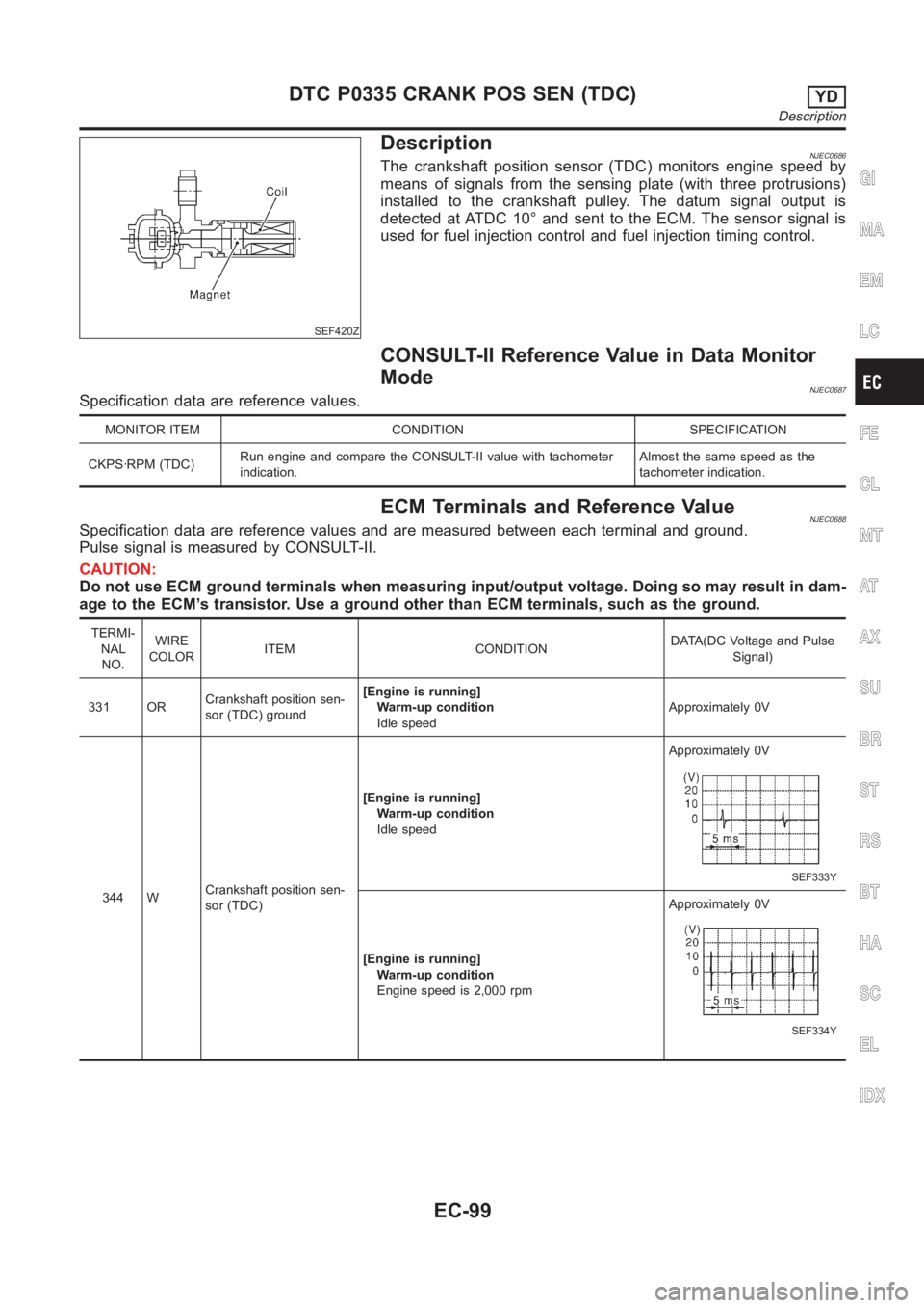
DescriptionNJEC0686The crankshaft position sensor (TDC) monitors engine speed by
means of signals from the sensing plate (with three protrusions)
installed to the crankshaft pulley. The datum signal output is
detected at ATDC 10° and sent to the ECM. The sensor signal is
used for fuel injection control and fuel injection timing control.
CONSULT-II Reference Value in Data Monitor
Mode
NJEC0687Specification data are reference values.
MONITOR ITEM CONDITION SPECIFICATION
CKPS·RPM (TDC)Run engine and compare the CONSULT-II value with tachometer
indication.Almost the same speed as the
tachometer indication.
ECM Terminals and Reference ValueNJEC0688Specification data are reference values and are measured between each terminal and ground.
Pulse signal is measured by CONSULT-II.
CAUTION:
Do not use ECM ground terminals when measuring input/output voltage. Doing so may result in dam-
age to the ECM’s transistor. Use a ground other than ECM terminals, such as the ground.
TERMI-
NAL
NO.WIRE
COLORITEM CONDITIONDATA(DC Voltage and Pulse
Signal)
331 ORCrankshaft position sen-
sor (TDC) ground[Engine is running]
Warm-up condition
Idle speedApproximately 0V
344 WCrankshaft position sen-
sor (TDC)[Engine is running]
Warm-up condition
Idle speedApproximately 0V
SEF333Y
[Engine is running]
Warm-up condition
Engine speed is 2,000 rpmApproximately 0V
SEF334Y
GI
MA
EM
LC
FE
CL
MT
AT
AX
SU
BR
ST
RS
BT
HA
SC
EL
IDX
DTC P0335 CRANK POS SEN (TDC)YD
Description
EC-99
Page 1987 of 3189

PRECAUTIONS
ATC-7
C
D
E
F
G
H
I
K
L
MA
B
AT C
●When installing an air conditioner in the vehicle, connect the pipes as the final stage of the opera-
tion. Do not remove the seal caps of pipes and other components until just before required for
connection.
●Allow components stored in cool areas to warm to working area temperature before removing seal
caps. This prevents condensation from forming inside A/C components.
●Thoroughly remove moisture from the refrigeration system before charging the refrigerant.
●Always replace used O-rings.
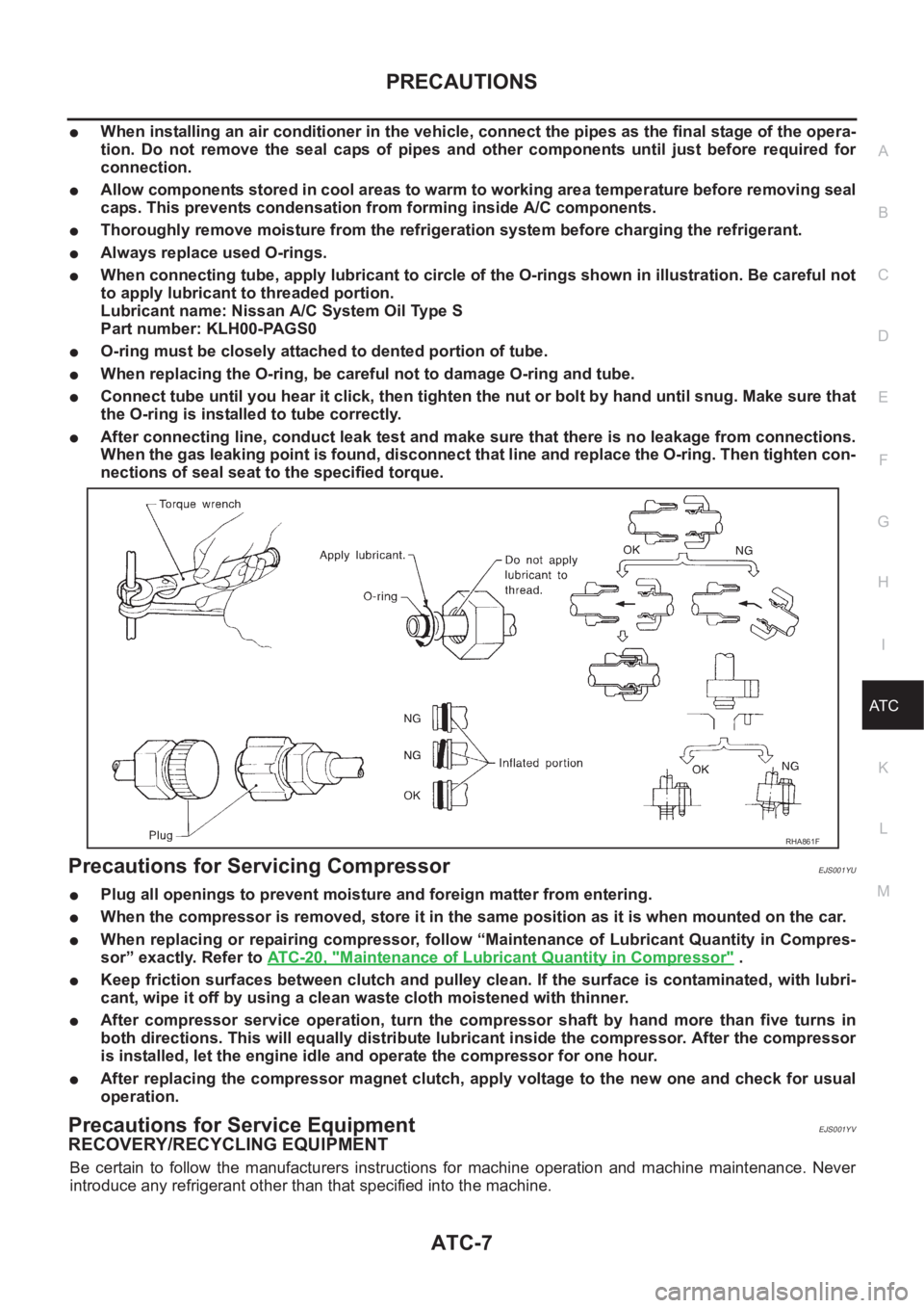
●When connecting tube, apply lubricant to circle of the O-rings shown in illustration. Be careful not
to apply lubricant to threaded portion.
Lubricant name: Nissan A/C System Oil Type S
Part number: KLH00-PAGS0
●O-ring must be closely attached to dented portion of tube.
●When replacing the O-ring, be careful not to damage O-ring and tube.
●Connect tube until you hear it click, then tighten the nut or bolt by hand until snug. Make sure that
the O-ring is installed to tube correctly.
●After connecting line, conduct leak test and make sure that there is no leakage from connections.
When the gas leaking point is found, disconnect that line and replace the O-ring. Then tighten con-
nections of seal seat to the specified torque.
Precautions for Servicing CompressorEJS001YU
●Plug all openings to prevent moisture and foreign matter from entering.
●When the compressor is removed, store it in the same position as it is when mounted on the car.
●When replacing or repairing compressor, follow “Maintenance of Lubricant Quantity in Compres-
sor” exactly. Refer to ATC-20, "
Maintenance of Lubricant Quantity in Compressor" .
●Keep friction surfaces between clutch and pulley clean. If the surface is contaminated, with lubri-
cant, wipe it off by using a clean waste cloth moistened with thinner.
●After compressor service operation, turn the compressor shaft by hand more than five turns in
both directions. This will equally distribute lubricant inside the compressor. After the compressor
is installed, let the engine idle and operate the compressor for one hour.
●After replacing the compressor magnet clutch, apply voltage to the new one and check for usual
operation.
Precautions for Service EquipmentEJS001YV
RECOVERY/RECYCLING EQUIPMENT
Be certain to follow the manufacturers instructions for machine operation and machine maintenance. Never
introduce any refrigerant other than that specified into the machine.
RHA861F
Page 1991 of 3189

PREPARATION
ATC-11
C
D
E
F
G
H
I
K
L
MA
B
AT C
PREPARATIONPFP:00002
Special Service ToolsEJS001YY
HFC-134a (R-134a) Service Tools and EquipmentEJS001YZ
Never mix HFC-134a (R-134a) refrigerant and/or its specified lubricant with CFC-12 (R-12) refrigerant and/or
its lubricant.
Separate and non-interchangeable service equipment must be used for handling each type of refrigerant/lubri-
cant.
Refrigerant container fittings, service hose fittings and service equipment fittings (equipment which handles
refrigerant and/or lubricant) are different between CFC-12 (R-12) and HFC-134a (R-134a). This is to avoid
mixed use of the refrigerants/lubricant.
Adapters that convert one size fitting to another must never be used: refrigerant/lubricant contamination will
occur and compressor malfunction will result.
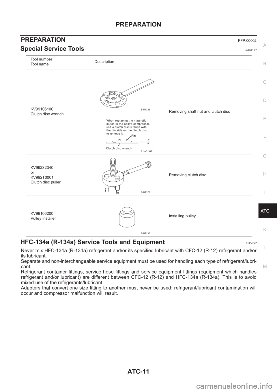
Tool number
Tool nameDescription
KV99106100
Clutch disc wrenchRemoving shaft nut and clutch disc
KV99232340
or
KV992T0001
Clutch disc pullerRemoving clutch disc
KV99106200
Pulley installerInstalling pulley
S-NT232
RJIA0194E
S-NT376
S-NT235
Page 2119 of 3189
REFRIGERANT LINES
ATC-139
C
D
E
F
G
H
I
K
L
MA
B
AT C
4. Position the center pulley puller on the end of the drive shaft,
and remove the pulley assembly using any commercially avail-
able pulley puller.
To prevent the pulley groove from being deformed, the puller
claws should be positioned into the edge of the pulley assembly.
5. Remove the field coil harness clip using a pair of pliers.
6. Remove the snap ring using external snap ring pliers.
Inspection
Clutch disc
If the contact surface shows signs of damage due to excessive heat,
replace clutch disc and pulley.
Pulley
Check the appearance of the pulley assembly. If the contact surface
of pulley sows signs of excessive grooving, replace clutch disc and
pulley. The contact surfaces of the pulley assembly should be
cleaned with a suitable solvent before reinstallation.
Coil
Check coil for loose connection or cracked insulation.
INSTALLATION
1. Install the field coil.
RHA139E
RHA125F
RHA145E
RHA126F
Page 2120 of 3189
ATC-140
REFRIGERANT LINES
Be sure to align the coil′s pin with the hole in the compressor′s
front head.
2. Install the field coil harness clip using a screwdriver.
3. Install the pulley assembly using the installer and a hand press,
and then install the snap ring using snap ring pliers.
4. Install the clutch disc on the drive shaft, together with the original
shim(s). Press the clutch disc down by hand.
5. Using the holder to prevent clutch disc rotation.
After tightening the bolt, check that the pulley rotates smoothly.
6. Check clearance around the entire periphery of clutch disc.
If the specified clearance is not obtained, replace adjusting
spacer and readjust.
RHA142E
RHA143EA
RHA127F
Tightening torque : 14 N·m (1.4 kg·m, 10 ft-lb)
RHA086E
Disc to pulley clear-
ance: 0.3 - 0.6 mm (0.012 - 0.024 in)
RHA087E