Page 197 of 3189
InstallationNJEM00911. Install each belt on pulley in reverse order of removal.
2. Adjust belt tension. Refer to EM-11, “Adjustment”.
3. Tighten nuts and bolts provided for adjustment to the specified
torque.
4. Check again that each belt tension is as specified.GI
MA
LC
EC
FE
CL
MT
AT
AX
SU
BR
ST
RS
BT
HA
SC
EL
IDX
DRIVE BELTSYD
Installation
EM-13
Page 204 of 3189
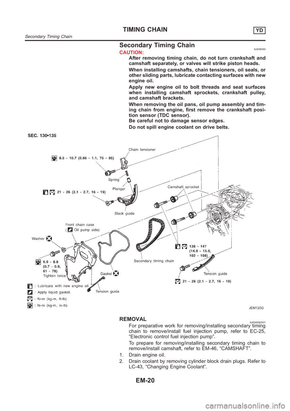
Secondary Timing ChainNJEM0093CAUTION:
After removing timing chain, do not turn crankshaft and
camshaft separately, or valves will strike piston heads.
When installing camshafts, chain tensioners, oil seals, or
other sliding parts, lubricate contacting surfaces with new
engine oil.
Apply new engine oil to bolt threads and seat surfaces
when installing camshaft sprockets, crankshaft pulley,
and camshaft brackets.
When removing the oil pans, oil pump assembly and tim-
ing chain from engine, first remove the crankshaft posi-
tion sensor (TDC sensor).
Be careful not to damage sensor edges.
Do not spill engine coolant on drive belts.
JEM120G
REMOVALNJEM0093S01For preparative work for removing/installing secondary timing
chain to remove/install fuel injection pump, refer to EC-25,
“Electronic control fuel injection pump”.
To prepare for removing/installing secondary timing chain to
remove/install camshaft, refer to EM-46, “CAMSHAFT”.
1. Drain engine oil.
2. Drain coolant by removing cylinder block drain plugs. Refer to
LC-43, “Changing Engine Coolant”.
TIMING CHAINYD
Secondary Timing Chain
EM-20
Page 205 of 3189
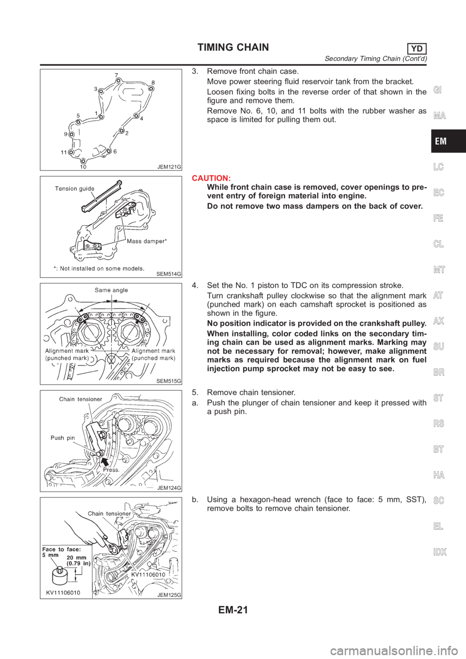
JEM121G
3. Remove front chain case.
Move power steering fluid reservoir tank from the bracket.
Loosen fixing bolts in the reverse order of that shown in the
figure and remove them.
Remove No. 6, 10, and 11 bolts with the rubber washer as
space is limited for pulling them out.
SEM514G
CAUTION:
While front chain case is removed, cover openings to pre-
vent entry of foreign material into engine.
Do not remove two mass dampers on the back of cover.
SEM515G
4. Set the No. 1 piston to TDC on its compression stroke.
Turn crankshaft pulley clockwise so that the alignment mark
(punched mark) on each camshaft sprocket is positioned as
shown in the figure.
No position indicator is provided on the crankshaft pulley.
When installing, color coded links on the secondary tim-
ing chain can be used as alignment marks. Marking may
not be necessary for removal; however, make alignment
marks as required because the alignment mark on fuel
injection pump sprocket may not be easy to see.
JEM124G
5. Remove chain tensioner.
a. Push the plunger of chain tensioner and keep it pressed with
a push pin.
JEM125G
b. Using a hexagon-head wrench (face to face: 5 mm, SST),
remove bolts to remove chain tensioner.
GI
MA
LC
EC
FE
CL
MT
AT
AX
SU
BR
ST
RS
BT
HA
SC
EL
IDX
TIMING CHAINYD
Secondary Timing Chain (Cont’d)
EM-21
Page 210 of 3189
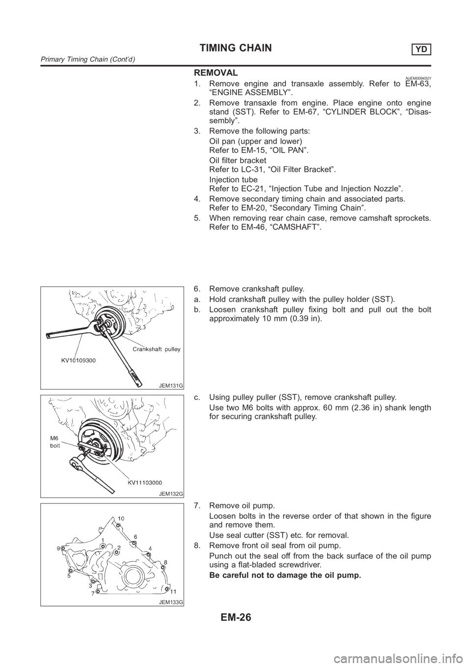
REMOVALNJEM0094S011. Remove engine and transaxle assembly. Refer to EM-63,
“ENGINE ASSEMBLY”.
2. Remove transaxle from engine. Place engine onto engine
stand (SST). Refer to EM-67, “CYLINDER BLOCK”, “Disas-
sembly”.
3. Remove the following parts:
Oil pan (upper and lower)
Refer to EM-15, “OIL PAN”.
Oil filter bracket
Refer to LC-31, “Oil Filter Bracket”.
Injection tube
Refer to EC-21, “Injection Tube and Injection Nozzle”.
4. Remove secondary timing chain and associated parts.
Refer to EM-20, “Secondary Timing Chain”.
5. When removing rear chain case, remove camshaft sprockets.
Refer to EM-46, “CAMSHAFT”.
JEM131G
6. Remove crankshaft pulley.
a. Hold crankshaft pulley with the pulley holder (SST).
b. Loosen crankshaft pulley fixing bolt and pull out the bolt
approximately 10 mm (0.39 in).
JEM132G
c. Using pulley puller (SST), remove crankshaft pulley.
Use two M6 bolts with approx. 60 mm (2.36 in) shank length
for securing crankshaft pulley.
JEM133G
7. Remove oil pump.
Loosen bolts in the reverse order of that shown in the figure
and remove them.
Use seal cutter (SST) etc. for removal.
8. Remove front oil seal from oil pump.
Punch out the seal off from the back surface of the oil pump
using a flat-bladed screwdriver.
Be careful not to damage the oil pump.
TIMING CHAINYD
Primary Timing Chain (Cont’d)
EM-26
Page 216 of 3189
JEM147G
15. Install crankshaft pulley.
a. Install crankshaft pulley to crankshaft.
b. Hold crankshaft pulley with the pulley holder (SST).
c. Tighten bolt to 20 to 29 N·m (2.0 to 3.0 kg-m, 15 to 21 ft-lb).
d. Put an alignment mark on crankshaft pulley that aligns with
one of the punched marks on the bolt.
e. Tighten fixing bolt another 60° - 66° [target: 60° (turn by one
notch)].
16. Install secondary timing chain and the associated parts.
Refer to EM-22, “Secondary Timing Chain”, “INSTALLATION”.
17. Install in the reverse order of removal hereafter.
TIMING CHAINYD
Primary Timing Chain (Cont’d)
EM-32
Page 230 of 3189
CAUTION:
When installing camshafts, chain tensioners, oil seals, or
other sliding parts, lubricate contacting surfaces with new
engine oil.
Apply new engine oil to threads and seat surfaces when
installing cylinder head, camshaft sprocket, crankshaft
pulley, and camshaft bracket.
Attach tags to valve lifters so as not to mix them up.
RemovalNJEM0063PREPARATIVE WORKNJEM0063S011. Drain engine coolant. Refer to LC-43, “Changing Engine Cool-
ant”.
2. Remove exhaust manifold. Refer to EM-38, “Removal”.
3. Remove intake manifold. Refer to EM-34, “Removal”.
Apply paint to camshaft sprockets for alignment during
installation.
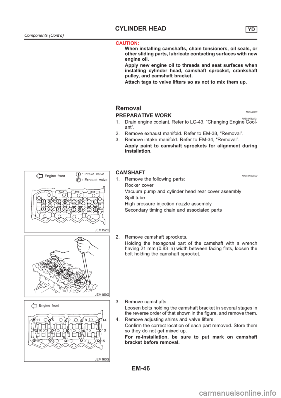
JEM152G
CAMSHAFTNJEM0063S021. Remove the following parts:
Rocker cover
Vacuum pump and cylinder head rear cover assembly
Spill tube
High pressure injection nozzle assembly
Secondary timing chain and associated parts
JEM159G
2. Remove camshaft sprockets.
Holding the hexagonal part of the camshaft with a wrench
having 21 mm (0.83 in) width between facing flats, loosen the
bolt holding the camshaft sprocket.
JEM160G
3. Remove camshafts.
Loosen bolts holding the camshaft bracket in several stages in
the reverse order of that shown in the figure, and remove them.
4. Remove adjusting shims and valve lifters.
Confirm the correct location of each part removed. Store them
so they do not get mixed up.
For re-installation, be sure to put mark on camshaft
bracket before removal.
CYLINDER HEADYD
Components (Cont’d)
EM-46
Page 243 of 3189
JEM175G
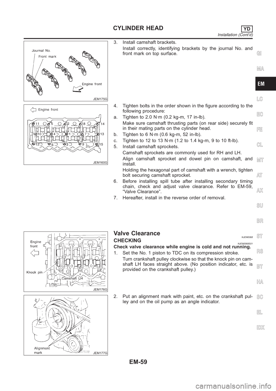
3. Install camshaft brackets.
Install correctly, identifying brackets by the journal No. and
front mark on top surface.
JEM160G
4. Tighten bolts in the order shown in the figure according to the
following procedure:
a. Tighten to 2.0 N·m (0.2 kg-m, 17 in-lb).
Make sure camshaft thrusting parts (on rear side) securely fit
in their mating parts on the cylinder head.
b. Tighten to 6 N·m (0.6 kg-m, 52 in-lb).
c. Tightento12to13N·m(1.2to1.4kg-m,9to10ft-lb).
5. Install camshaft sprockets.
Camshaft sprockets are commonly used for RH and LH.
Align camshaft sprocket and dowel pin on camshaft, and
install.
Holding the hexagonal part of camshaft with a wrench, tighten
bolt securing camshaft sprocket.
6. Before installing spill tube after installing secondary timing
chain, check and adjust valve clearance. Refer to EM-59,
“Valve Clearance”.
7. Hereafter, install in the reverse order of removal.
JEM176G
Valve ClearanceNJEM0068CHECKINGNJEM0068S01Check valve clearance while engine is cold and not running.
1. Set the No. 1 piston to TDC on its compression stroke.
Turn crankshaft pulley clockwise so that the knock pin on cam-
shaft LH faces straight above. (No position indicator, etc. is
provided on the crankshaft pulley.)
JEM177G
2. Put an alignment mark with paint, etc. on the crankshaft pul-
ley and on the oil pump as an angle indicator.
GI
MA
LC
EC
FE
CL
MT
AT
AX
SU
BR
ST
RS
BT
HA
SC
EL
IDX
CYLINDER HEADYD
Installation (Cont’d)
EM-59
Page 251 of 3189
Removal and InstallationNJEM0071CAUTION:
When installing bearings, pistons, or other sliding parts,
lubricate contacting surfaces with new engine oil.
Place removed parts such as bearings and bearing caps
in their proper order and direction.
When installing connecting rod nuts, and main bearing
cap bolts, apply new engine oil to threads and seating
surfaces.
Do not allow any magnetic materials to contact the signal
plate of flywheel.
Do not remove the signal plate at back.
Do not place the signal plate side facing under.
Handle with care so as not to damage the signal plate
[especially four places on protrusions for signal of crank
position sensor (TDC sensor)].
DisassemblyNJEM0072PISTON AND CRANKSHAFTNJEM0072S011. Remove engine. Refer to “ENGINE ASSEMBLY”, “Removal
and Installation”, EM-63.
2. Place engine on a work stand.
a. Remove flywheel.
Hold ring gear with ring gear stopper (KV10105630,
KV10105610). Then, loosen securing bolts with TORX socket
(size: Q8 E20, Commercial Service Tool) and remove them.
As an alternative method, hold the crankshaft pulley with a
pulley holder (SST) to remove the flywheel.
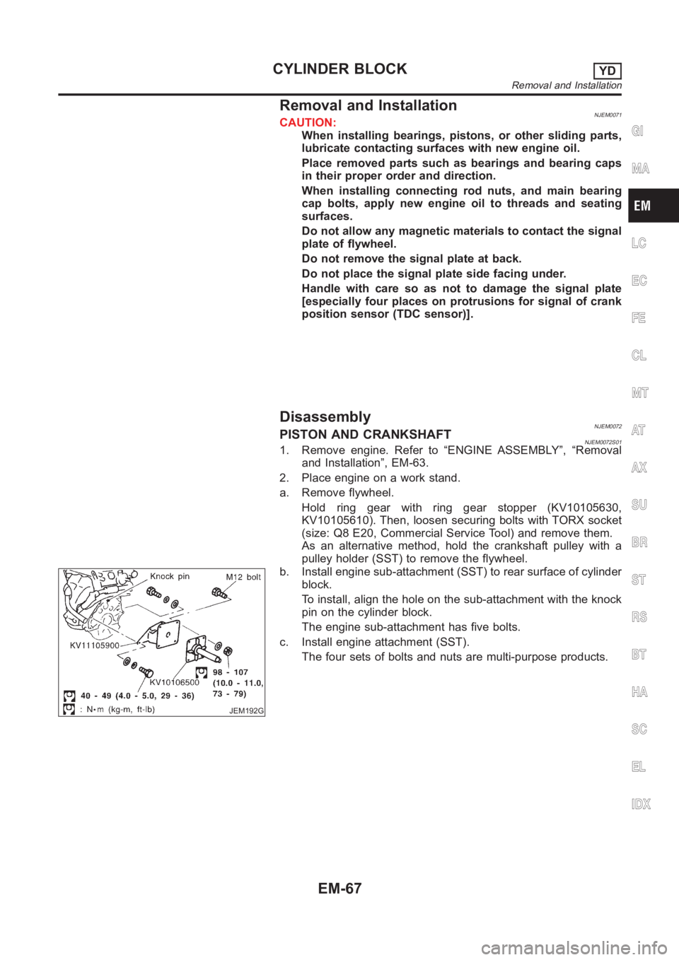
JEM192G
b. Install engine sub-attachment (SST) to rear surface of cylinder
block.
To install, align the hole on the sub-attachment with the knock
pin on the cylinder block.
The engine sub-attachment has five bolts.
c. Install engine attachment (SST).
The four sets of bolts and nuts are multi-purpose products.
GI
MA
LC
EC
FE
CL
MT
AT
AX
SU
BR
ST
RS
BT
HA
SC
EL
IDX
CYLINDER BLOCKYD
Removal and Installation
EM-67