2003 NISSAN ALMERA N16 fuel
[x] Cancel search: fuelPage 2400 of 3189
YEL812D
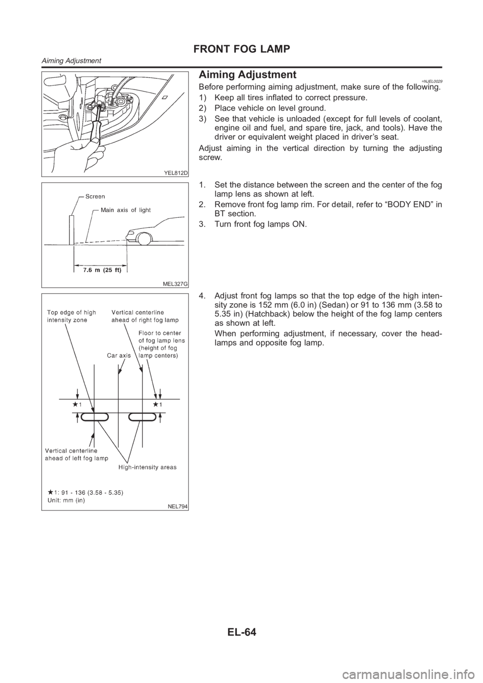
Aiming Adjustment=NJEL0029Before performing aiming adjustment, make sure of the following.
1) Keep all tires inflated to correct pressure.
2) Place vehicle on level ground.
3) See that vehicle is unloaded (except for full levels of coolant,
engine oil and fuel, and spare tire, jack, and tools). Have the
driver or equivalent weight placed in driver’s seat.
Adjust aiming in the vertical direction by turning the adjusting
screw.
MEL327G
1. Set the distance between the screen and the center of the fog
lamp lens as shown at left.
2. Remove front fog lamp rim. For detail, refer to “BODY END” in
BT section.
3. Turn front fog lamps ON.
NEL794
4. Adjust front fog lamps so that the top edge of the high inten-
sity zone is 152 mm (6.0 in) (Sedan) or 91 to 136 mm (3.58 to
5.35 in) (Hatchback) below the height of the fog lamp centers
as shown at left.
When performing adjustment, if necessary, cover the head-
lamps and opposite fog lamp.
FRONT FOG LAMP
Aiming Adjustment
EL-64
Page 2446 of 3189
Component Parts and Harness Connector
Location
NJEL0441For details, refer to “ELECTRICAL UNIT LOCATION” (EL-543) and
“HARNESS LAYOUT” (EL-550).
System DescriptionNJEL0442UNIFIED CONTROL METERNJEL0442S01Speedometer, odo/trip meter, tachometer, fuel gauge and water temperature gauge are controlled totally
by control unit built-in combination meter.
Digital meter is adopted for odo/trip meter.*
*The record of the odo meter is kept even if the battery cable is disconnected. The record of the trip meter
is erased when the battery cable is disconnected.
Odo/trip meter segment can be checked in diagnosis mode.
Meter/gauge can be checked in diagnosis mode.
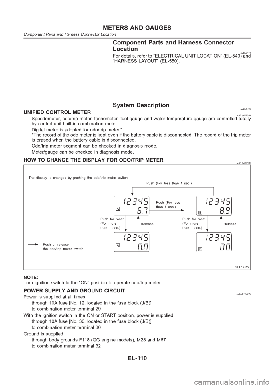
HOW TO CHANGE THE DISPLAY FOR ODO/TRIP METERNJEL0442S02
SEL175W
NOTE:
Turn ignition switch to the “ON” position to operate odo/trip meter.
POWER SUPPLY AND GROUND CIRCUITNJEL0442S03Power is supplied at all times
through 10A fuse [No. 12, located in the fuse block (J/B)]
to combination meter terminal 29
With the ignition switch in the ON or START position, power is supplied
through 10A fuse [No. 30, located in the fuse block (J/B)]
to combination meter terminal 30
Ground is supplied
through body grounds F118 (QG engine models), M28 and M67
to combination meter terminal 32
METERS AND GAUGES
Component Parts and Harness Connector Location
EL-110
Page 2447 of 3189
WATER TEMPERATURE GAUGE (QG AND YD ENGINE MODELS WITH COMMON RAIL)NJEL0442S09The water temperature gauge indicates the engine coolant temperature.
ECM provides a engine coolant temperature signal to combination meter forwater temperature gauge with
CAN communication line.
WATER TEMPERATURE GAUGE (YD ENGINE MODELS WITHOUT COMMON RAIL)NJEL0442S04The water temperature gauge indicates the engine coolant temperature. The reading on the gauge is based
on the resistance of the thermal transmitter.
As the temperature of the coolant increases, the resistance of the thermaltransmitter decreases. A variable
ground is supplied to terminal 35 of the combination meter for the water temperature gauge. The needle on
the gauge moves from “C” to “H”.
TACHOMETER (QG AND YD ENGINE MODELS WITH COMMON RAIL)NJEL0442S10The tachometer indicates engine speed in revolution per minutes (rpm). ECM provides an engine speed sig-
nal to combination meter for tachometer with CAN communication line.
TACHOMETER (YD ENGINE MODELS WITHOUT COMMON RAIL)NJEL0442S05The tachometer indicates engine speed in revolutions per minute (rpm).
The tachometer is regulated by a signal
from terminal 32 (Gasoline engine models) or 439 (Diesel engine models) ofthe ECM
to combination meter terminal 53 for the tachometer.
FUEL GAUGENJEL0442S06The fuel gauge indicates the approximate fuel level in the fuel tank.
The fuel gauge is regulated by a variable ground signal supplied
from body grounds F118 (QG engine models), M28 and M67
through terminals 33 and 32 of combination meter,
through terminal 1 of the fuel level sensor unit and
through terminal 4 of the fuel level sensor unit
to combination meter terminal 34 for the fuel gauge.
SPEEDOMETER (MODELS WITH ABS)NJEL0442S11The combination meter receives a signal from the ABS actuator and electricunit. The speedometer converts
the signal into the vehicle speed displayed.
SPEEDOMETER (MODELS WITHOUT ABS)NJEL0442S07The combination meter provides a voltage signal to the vehicle speed sensor for the speedometer.
The voltage is supplied
from combination meter terminal 13 for the speedometer
to terminal 1 of the vehicle speed sensor.
Ground is supplied
from body grounds F118 (QG engine models), M28 and M67
through terminals 32 and 14 of combination meter
to teminal 2 of the vehicle speed sensor.
The speedometer converts the voltage into the vehicle speed displayed.
GI
MA
EM
LC
EC
FE
CL
MT
AT
AX
SU
BR
ST
RS
BT
HA
SC
IDX
METERS AND GAUGES
System Description (Cont’d)
EL-111
Page 2453 of 3189
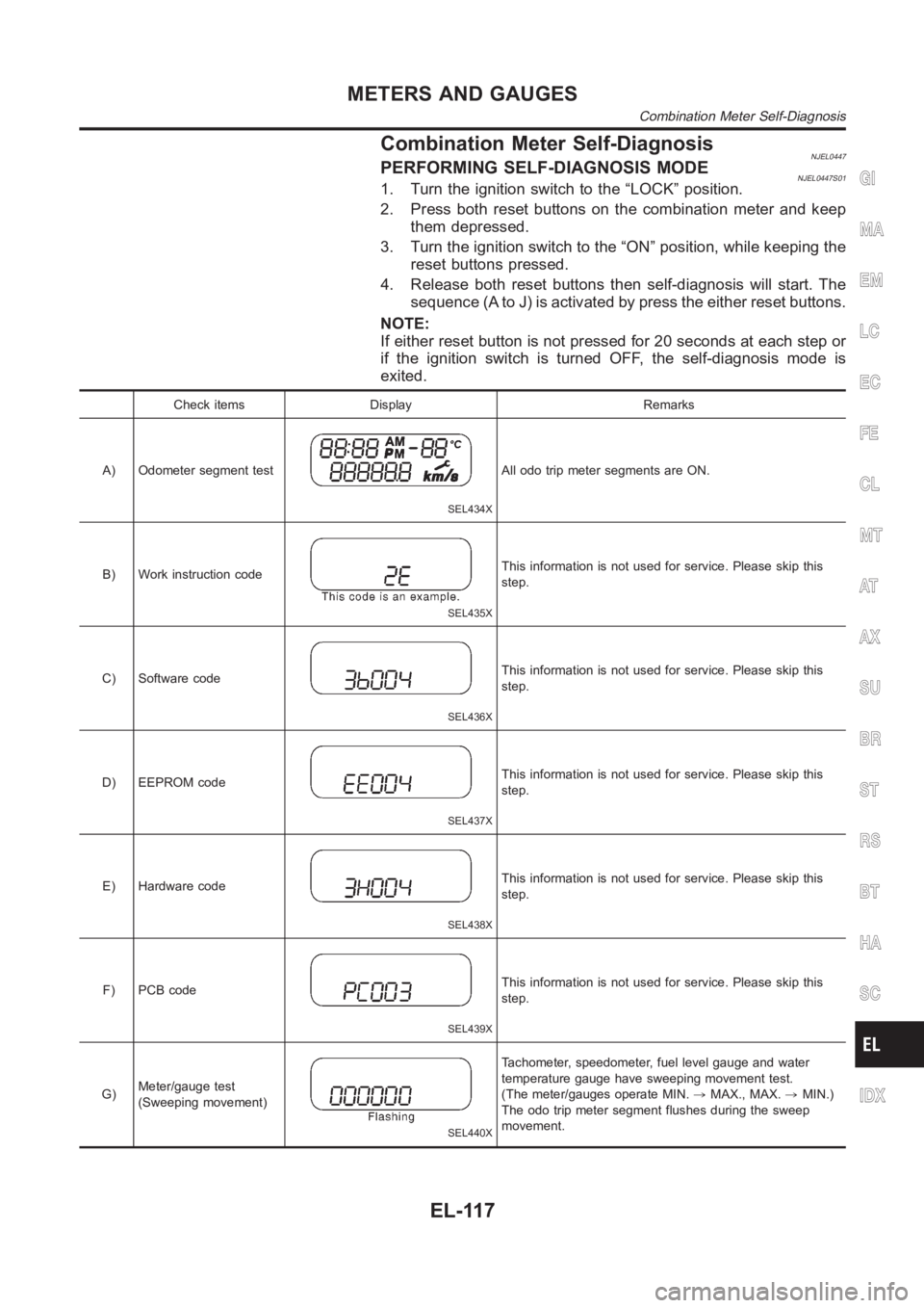
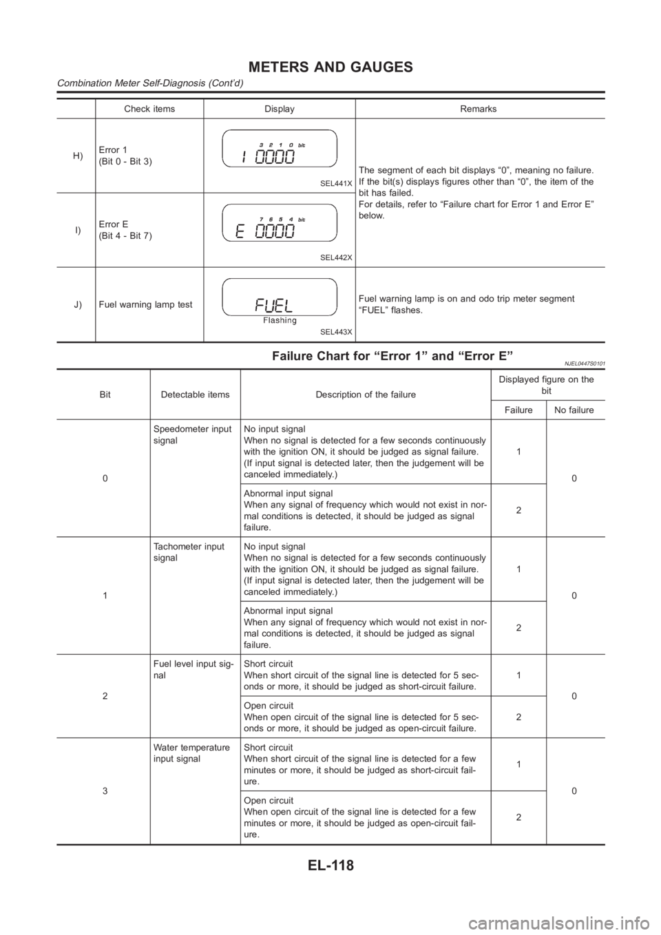
Combination Meter Self-DiagnosisNJEL0447PERFORMING SELF-DIAGNOSIS MODENJEL0447S011. Turn the ignition switch to the “LOCK” position.
2. Press both reset buttons on the combination meter and keep
them depressed.
3. Turn the ignition switch to the “ON” position, while keeping the
reset buttons pressed.
4. Release both reset buttons then self-diagnosis will start. The
sequence (A to J) is activated by press the either reset buttons.
NOTE:
If either reset button is not pressed for 20 seconds at each step or
if the ignition switch is turned OFF, the self-diagnosis mode is
exited.
Check items Display Remarks
A) Odometer segment test
SEL434X
All odo trip meter segments are ON.
B) Work instruction code
SEL435X
This information is not used for service. Please skip this
step.
C) Software code
SEL436X
This information is not used for service. Please skip this
step.
D) EEPROM code
SEL437X
This information is not used for service. Please skip this
step.
E) Hardware code
SEL438X
This information is not used for service. Please skip this
step.
F) PCB code
SEL439X
This information is not used for service. Please skip this
step.
G)Meter/gauge test
(Sweeping movement)
SEL440X
Tachometer, speedometer, fuel level gauge and water
temperature gauge have sweeping movement test.
(The meter/gauges operate MIN.,MAX., MAX.,MIN.)
The odo trip meter segment flushes during the sweep
movement.
GI
MA
EM
LC
EC
FE
CL
MT
AT
AX
SU
BR
ST
RS
BT
HA
SC
IDX
METERS AND GAUGES
Combination Meter Self-Diagnosis
EL-117
Page 2454 of 3189
Check items Display Remarks
H)Error 1
(Bit 0 - Bit 3)
SEL441X
The segment of each bit displays “0”, meaning no failure.
If the bit(s) displays figures other than “0”, the item of the
bit has failed.
For details, refer to “Failure chart for Error 1 and Error E”
below.
I)Error E
(Bit 4 - Bit 7)
SEL442X
J) Fuel warning lamp test
SEL443X
Fuel warning lamp is on and odo trip meter segment
“FUEL” flashes.
Failure Chart for “Error 1” and “Error E”NJEL0447S0101
Bit Detectable items Description of the failureDisplayed figure on the
bit
Failure No failure
0Speedometer input
signalNo input signal
When no signal is detected for a few seconds continuously
with the ignition ON, it should be judged as signal failure.
(If input signal is detected later, then the judgement will be
canceled immediately.)1
0
Abnormal input signal
When any signal of frequency which would not exist in nor-
mal conditions is detected, it should be judged as signal
failure.2
1Tachometer input
signalNo input signal
When no signal is detected for a few seconds continuously
with the ignition ON, it should be judged as signal failure.
(If input signal is detected later, then the judgement will be
canceled immediately.)1
0
Abnormal input signal
When any signal of frequency which would not exist in nor-
mal conditions is detected, it should be judged as signal
failure.2
2Fuel level input sig-
nalShort circuit
When short circuit of the signal line is detected for 5 sec-
onds or more, it should be judged as short-circuit failure.1
0
Open circuit
When open circuit of the signal line is detected for 5 sec-
onds or more, it should be judged as open-circuit failure.2
3Water temperature
input signalShort circuit
When short circuit of the signal line is detected for a few
minutes or more, it should be judged as short-circuit fail-
ure.1
0
Open circuit
When open circuit of the signal line is detected for a few
minutes or more, it should be judged as open-circuit fail-
ure.2
METERS AND GAUGES
Combination Meter Self-Diagnosis (Cont’d)
EL-118
Page 2457 of 3189
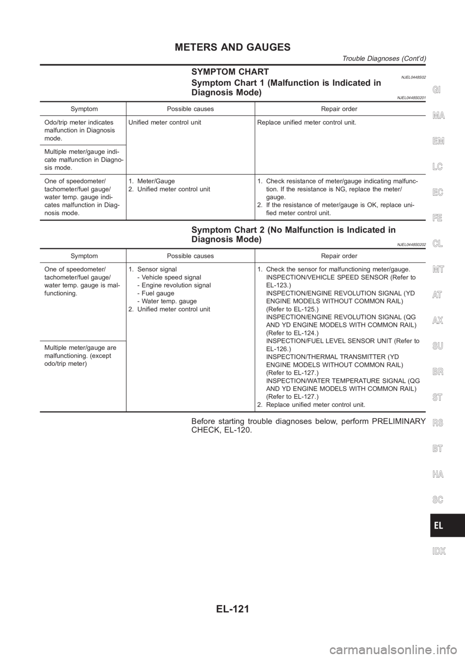
SYMPTOM CHARTNJEL0448S02Symptom Chart 1 (Malfunction is Indicated in
Diagnosis Mode)
NJEL0448S0201
Symptom Possible causes Repair order
Odo/trip meter indicates
malfunction in Diagnosis
mode.Unified meter control unit Replace unified meter control unit.
Multiple meter/gauge indi-
cate malfunction in Diagno-
sis mode.
One of speedometer/
tachometer/fuel gauge/
water temp. gauge indi-
cates malfunction in Diag-
nosis mode.1. Meter/Gauge
2. Unified meter control unit1. Check resistance of meter/gauge indicating malfunc-
tion. If the resistance is NG, replace the meter/
gauge.
2. If the resistance of meter/gauge is OK, replace uni-
fied meter control unit.
Symptom Chart 2 (No Malfunction is Indicated in
Diagnosis Mode)
NJEL0448S0202
Symptom Possible causes Repair order
One of speedometer/
tachometer/fuel gauge/
water temp. gauge is mal-
functioning.1. Sensor signal
- Vehicle speed signal
- Engine revolution signal
- Fuel gauge
- Water temp. gauge
2. Unified meter control unit1. Check the sensor for malfunctioning meter/gauge.
INSPECTION/VEHICLE SPEED SENSOR (Refer to
EL-123.)
INSPECTION/ENGINE REVOLUTION SIGNAL (YD
ENGINE MODELS WITHOUT COMMON RAIL)
(Refer to EL-125.)
INSPECTION/ENGINE REVOLUTION SIGNAL (QG
AND YD ENGINE MODELS WITH COMMON RAIL)
(Refer to EL-124.)
INSPECTION/FUEL LEVEL SENSOR UNIT (Refer to
EL-126.)
INSPECTION/THERMAL TRANSMITTER (YD
ENGINE MODELS WITHOUT COMMON RAIL)
(Refer to EL-127.)
INSPECTION/WATER TEMPERATURE SIGNAL (QG
AND YD ENGINE MODELS WITH COMMON RAIL)
(Refer to EL-127.)
2. Replace unified meter control unit. Multiple meter/gauge are
malfunctioning. (except
odo/trip meter)
Before starting trouble diagnoses below, perform PRELIMINARY
CHECK, EL-120.
GI
MA
EM
LC
EC
FE
CL
MT
AT
AX
SU
BR
ST
RS
BT
HA
SC
IDX
METERS AND GAUGES
Trouble Diagnoses (Cont’d)
EL-121
Page 2462 of 3189
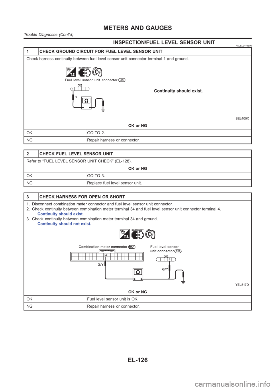
INSPECTION/FUEL LEVEL SENSOR UNIT=NJEL0448S06
1 CHECK GROUND CIRCUIT FOR FUEL LEVEL SENSOR UNIT
Check harness continuity between fuel level sensor unit connector terminal 1 and ground.
SEL400X
OK or NG
OK GO TO 2.
NG Repair harness or connector.
2 CHECK FUEL LEVEL SENSOR UNIT
Refer to “FUEL LEVEL SENSOR UNIT CHECK” (EL-128).
OK or NG
OK GO TO 3.
NG Replace fuel level sensor unit.
3 CHECK HARNESS FOR OPEN OR SHORT
1. Disconnect combination meter connector and fuel level sensor unit connector.
2. Check continuity between combination meter terminal 34 and fuel level sensor unit connector terminal 4.
Continuity should exist.
3. Check continuity between combination meter terminal 34 and ground.
Continuity should not exist.
YEL817D
OK or NG
OK Fuel level sensor unit is OK.
NG Repair harness or connector.
METERS AND GAUGES
Trouble Diagnoses (Cont’d)
EL-126
Page 2464 of 3189
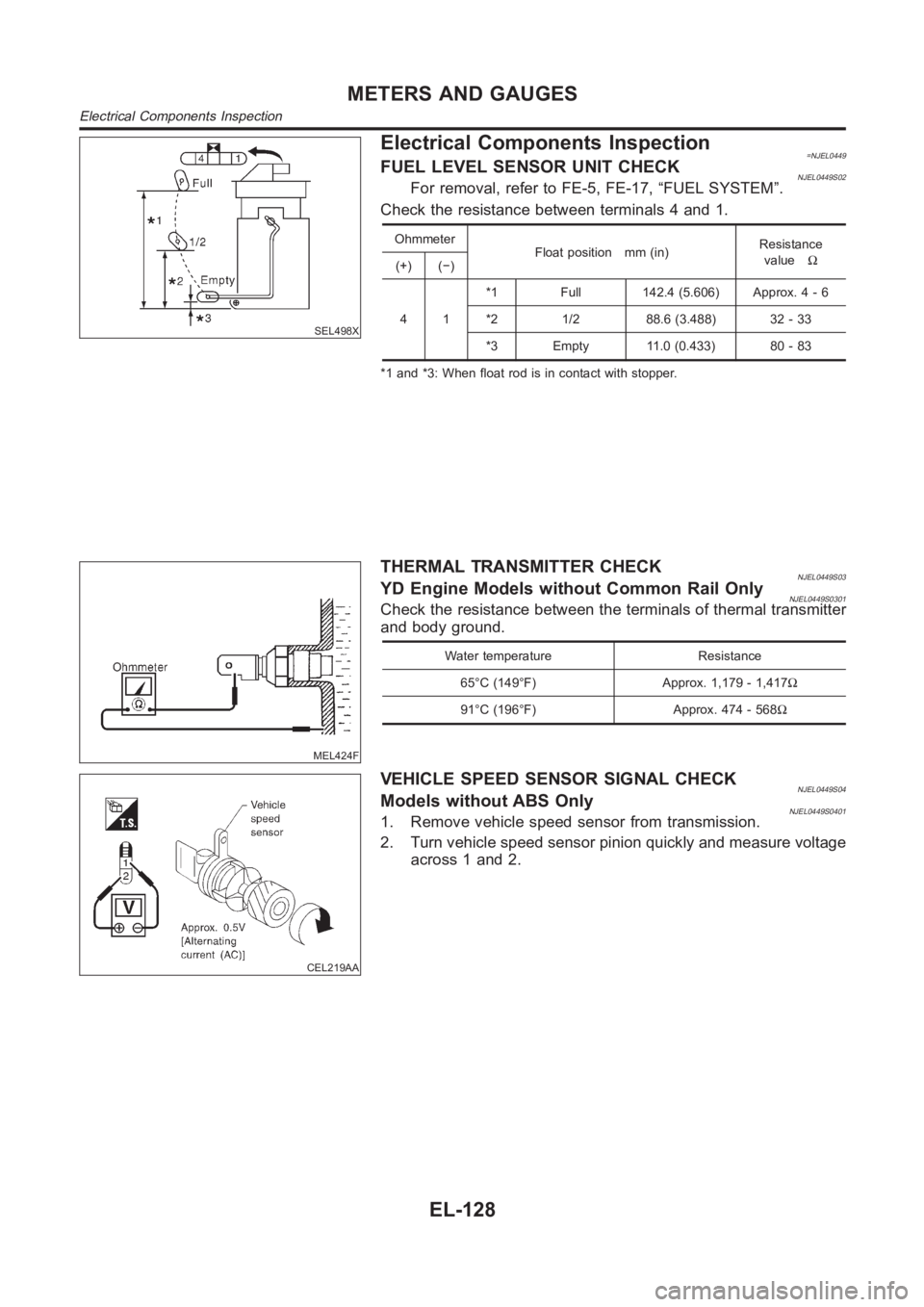
SEL498X
Electrical Components Inspection=NJEL0449FUEL LEVEL SENSOR UNIT CHECKNJEL0449S02For removal, refer to FE-5, FE-17, “FUEL SYSTEM”.
Check the resistance between terminals 4 and 1.
Ohmmeter
Float position mm (in)Resistance
valueΩ
(+) (−)
41*1 Full 142.4 (5.606) Approx. 4 - 6
*2 1/2 88.6 (3.488) 32 - 33
*3 Empty 11.0 (0.433) 80 - 83
*1 and *3: When float rod is in contact with stopper.
MEL424F
THERMAL TRANSMITTER CHECKNJEL0449S03YD Engine Models without Common Rail OnlyNJEL0449S0301Check the resistance between the terminals of thermal transmitter
and body ground.
Water temperature Resistance
65°C (149°F) Approx. 1,179 - 1,417Ω
91°C (196°F) Approx. 474 - 568Ω
CEL219AA
VEHICLE SPEED SENSOR SIGNAL CHECKNJEL0449S04Models without ABS OnlyNJEL0449S04011. Remove vehicle speed sensor from transmission.
2. Turn vehicle speed sensor pinion quickly and measure voltage
across 1 and 2.
METERS AND GAUGES
Electrical Components Inspection
EL-128