Page 2595 of 3189
YEL747D
GI
MA
EM
LC
EC
FE
CL
MT
AT
AX
SU
BR
ST
RS
BT
HA
SC
IDX
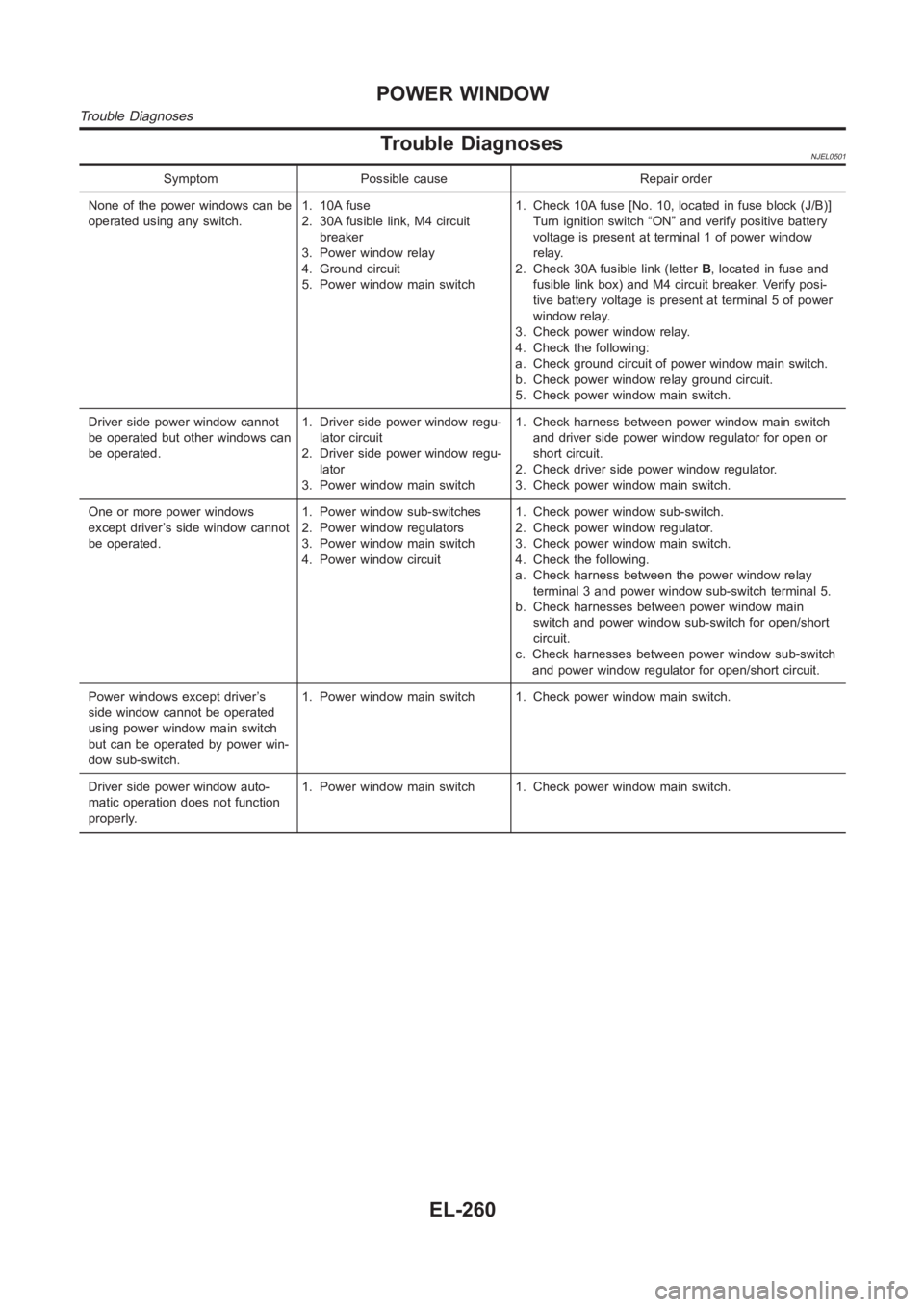
POWER WINDOW
Wiring Diagram — WINDOW — (Cont’d)
EL-259
Page 2596 of 3189

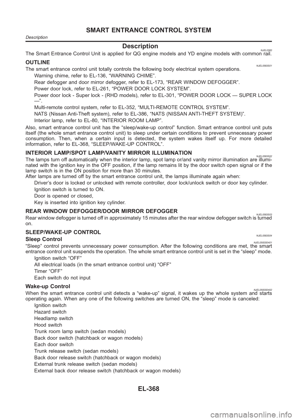
Trouble DiagnosesNJEL0501
Symptom Possible cause Repair order
None of the power windows can be
operated using any switch.1. 10A fuse
2. 30A fusible link, M4 circuit
breaker
3. Power window relay
4. Ground circuit
5. Power window main switch1. Check 10A fuse [No. 10, located in fuse block (J/B)]
Turn ignition switch “ON” and verify positive battery
voltage is present at terminal 1 of power window
relay.
2. Check 30A fusible link (letterB, located in fuse and
fusible link box) and M4 circuit breaker. Verify posi-
tive battery voltage is present at terminal 5 of power
window relay.
3. Check power window relay.
4. Check the following:
a. Check ground circuit of power window main switch.
b. Check power window relay ground circuit.
5. Check power window main switch.
Driver side power window cannot
be operated but other windows can
be operated.1. Driver side power window regu-
lator circuit
2. Driver side power window regu-
lator
3. Power window main switch1. Check harness between power window main switch
and driver side power window regulator for open or
short circuit.
2. Check driver side power window regulator.
3. Check power window main switch.
One or more power windows
except driver’s side window cannot
be operated.1. Power window sub-switches
2. Power window regulators
3. Power window main switch
4. Power window circuit1. Check power window sub-switch.
2. Check power window regulator.
3. Check power window main switch.
4. Check the following.
a. Check harness between the power window relay
terminal 3 and power window sub-switch terminal 5.
b. Check harnesses between power window main
switch and power window sub-switch for open/short
circuit.
c. Check harnesses between power window sub-switch
and power window regulator for open/short circuit.
Power windows except driver’s
side window cannot be operated
using power window main switch
but can be operated by power win-
dow sub-switch.1. Power window main switch 1. Check power window main switch.
Driver side power window auto-
matic operation does not function
properly.1. Power window main switch 1. Check power window main switch.
POWER WINDOW
Trouble Diagnoses
EL-260
Page 2612 of 3189
2 CHECK DOOR LOCK/UNLOCK SWITCH
1. Disconnect door lock/unlock switch harness connector.
2. Check continuity between each door lock/unlock switch terminals.
Power window main switch (Door lock/unlock switch) (With power window system)
YEL803C
Door lock/unlock switch (Without power window system)
SEL469X
OK or NG
OKCheck the following.
Ground circuit for door lock/unlock switch
Harness for open or short between door lock/unlock switch and smart entrance control
unit connector
NG Replace power window main switch (door lock/unlock switch).
POWER DOOR LOCK
Trouble Diagnosis/QG and YD Engine Models with Common Rail (Cont’d)
EL-276
Page 2630 of 3189
DOOR LOCK/UNLOCK SWITCH CHECK=NJEL0505S04
1 CHECK DOOR LOCK/UNLOCK SWITCH INPUT SIGNAL
1. Disconnect time control unit harness connector.
2. Check continuity between time control unit harness connector terminal37 or 38 and ground.
SEL468X
Refer to wiring diagram in EL-266.
OK or NG
OK Door lock/unlock switch is OK.
NG GO TO 2.
2 CHECK DOOR LOCK/UNLOCK SWITCH
1. Disconnect door lock/unlock switch harness connector.
2. Check continuity between each door lock/unlock switch terminals.
Power window main switch (Door lock/unlock switch) (With power window)
YEL801C
Door lock/unlock switch (Without power window)
SEL469X
OK or NG
OKCheck the following.
Ground circuit for door lock/unlock switch
Harness for open or short between door lock/unlock switch and time controlunit con-
nector
NG Replace door lock/unlock switch.
POWER DOOR LOCK
Trouble Diagnoses/YD Engine Models with Common Rail and K9K Engine Models(Cont’d)
EL-294
Page 2656 of 3189
2 CHECK DOOR LOCK/UNLOCK SWITCH
1. Disconnect door lock/unlock switch harness connector.
2. Check continuity between each door lock/unlock switch terminals.
Power window main switch (Door lock/unlock switch) (With power window system)
YEL803C
Door lock/unlock switch (Without power window system)
SEL469X
OK or NG
OKCheck the following.
Ground circuit for door lock/unlock switch
Harness for open or short between door lock/unlock switch and smart entrance control
unit connector
NG Replace power window main switch (door lock/unlock switch).
POWER DOOR LOCK — SUPER LOCK —
Trouble Diagnosis/QG and YD Engine Models with Common Rail (Cont’d)
EL-320
Page 2678 of 3189
DOOR LOCK/UNLOCK SWITCH CHECK=NJEL0477S04
1 CHECK DOOR LOCK/UNLOCK SWITCH INPUT SIGNAL
1. Disconnect time control unit harness connector.
2. Check continuity between time control unit harness connector terminal37 or 38 and ground.
SEL468X
Refer to wiring diagram in EL-308.
OK or NG
OK Door lock/unlock switch is OK.
NG GO TO 2.
2 CHECK DOOR LOCK/UNLOCK SWITCH
1. Disconnect door lock/unlock switch harness connector.
2. Check continuity between each door lock/unlock switch terminals.
Power window main switch (Door lock/unlock switch) (With power window)
YEL803C
Door lock/unlock switch (Without power window)
SEL469X
OK or NG
OKCheck the following.
Ground circuit for door lock/unlock switch
Harness for open or short between door lock/unlock switch and time controlunit con-
nector
NG Replace door lock/unlock switch.
POWER DOOR LOCK — SUPER LOCK —
Trouble Diagnoses/YD Engine Models without Common Rail and K9K Engine Models (Cont’d)
EL-342
Page 2704 of 3189

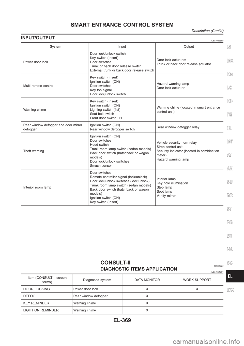
DescriptionNJEL0583The Smart Entrance Control Unit is applied for QG engine models and YD engine models with common rail.
OUTLINENJEL0583S01The smart entrance control unit totally controls the following body electrical system operations.
Warning chime, refer to EL-136, “WARNING CHIME”.
Rear defogger and door mirror defogger, refer to EL-173, “REAR WINDOW DEFOGGER”.
Power door lock, refer to EL-261, “POWER DOOR LOCK SYSTEM”.
Power door lock - Super lock - (RHD models), refer to EL-301, “POWER DOOR LOCK — SUPER LOCK
—”.
Multi-remote control system, refer to EL-352, “MULTI-REMOTE CONTROL SYSTEM”.
NATS (Nissan Anti-Theft system), refer to EL-386, “NATS (NISSAN ANTI-THEFT SYSTEM)”.
Interior lamp, refer to EL-80, “INTERIOR ROOM LAMP”.
Also, smart entrance control unit has the “sleep/wake-up control” function. Smart entrance control unit puts
itself (the whole smart entrance control unit) to sleep under certain conditions to prevent unnecessary power
consumption. Then, when a certain input is detected, the system wakes itself up. For more detailed
information, refer to EL-368, “SLEEP/WAKE-UP CONTROL”.
INTERIOR LAMP/SPOT LAMP/VANITY MIRROR ILLUMINATIONNJEL0583S02The lamps turn off automatically when the interior lamp, spot lamp or/and vanity mirror illumination are illumi-
nated with the ignition key in the OFF position, if the lamp remains lit by the door switch open signal or if the
lamp switch is in the ON position for more than 30 minutes.
After lamps are turned off by the smart entrance control unit, the lamps illuminate again when:
Driver’s door is locked or unlocked with remote controller, door lock/unlock switch or door key cylinder.
Ignition switch is turned to ON.
Door is opened or closed,
Key is inserted into ignition key cylinder.
REAR WINDOW DEFOGGER/DOOR MIRROR DEFOGGERNJEL0583S03Rear window defogger is turned off in approximately 15 minutes after the rear window defogger switch is turned
on.
SLEEP/WAKE-UP CONTROLNJEL0583S04Sleep ControlNJEL0583S0401“Sleep” control prevents unnecessary power consumption. After the following conditions are met, the smart
entrance control unit suspends the operation. The whole smart entrance control unit is set in the “sleep” mode.
Ignition switch “OFF”
All electrical loads (in the smart entrance control unit) “OFF”
Timer “OFF”
Each switch do not input
Wake-up ControlNJEL0583S0402When the smart entrance control unit detects a “wake-up” signal, it wakes up the whole system and starts
operating again. When any one of the following switches are turned ON, the “sleep” mode is canceled:
Ignition switch
Hazard switch
Headlamp switch
Hood switch
Trunk room lamp switch (sedan models)
Back door switch (hatchback or wagon models)
Each door switch
Trunk release switch (sedan models)
Back door release switch (hatchback or wagon models)
External trunk release switch (sedan models)
External back door release switch (hatchback or wagon models)
SMART ENTRANCE CONTROL SYSTEM
Description
EL-368
Page 2705 of 3189

INPUT/OUTPUTNJEL0583S05
System Input Output
Power door lockDoor lock/unlock switch
Key switch (Insert)
Door switches
Trunk or back door release switch
External trunk or back door release switchDoor lock actuators
Trunk or back door release actuator
Multi-remote controlKey switch (Insert)
Ignition switch (ON)
Door switches
Key fob signal
Door lock/unlock switchHazard warning lamp
Door lock actuator
Warning chimeKey switch (Insert)
Ignition switch (ON)
Lighting switch (1st)
Seat belt switch
Front door switch LHWarning chime (located in smart entrance
control unit)
Rear window defogger and door mirror
defoggerIgnition switch (ON)
Rear window defogger switchRear window defogger relay
Theft warningIgnition switch (ON)
Door switches
Hood switch
Trunk room lamp switch (sedan models)
Back door switch (hatchback or wagon
models)
Door lock/unlock switches
Smash sensorVehicle security horn relay
Siren control unit
Security indicator (located in combination
meter)
Hazard warning lamp
Interior room lampDoor switches
Remote controller signal (lock/unlock)
Door lock/unlock switches (lock/unlock)
Trunk room lamp switch (sedan models)
Back door switch (hatchback or wagon
models)
Ignition switch (ON)
Key switch (Insert)Interior lamp
Key hole illumination
Step lamp
Spot lamp
Vanity mirror
CONSULT-IINJEL0584DIAGNOSTIC ITEMS APPLICATIONNJEL0584S01
Item (CONSULT-II screen
terms)Diagnosed system DATA MONITOR WORK SUPPORT
DOOR LOCKING Power door lock X X
DEFOG Rear window defogger X
KEY REMINDER Warning chime X
LIGHT ON REMINDER Warning chime X
GI
MA
EM
LC
EC
FE
CL
MT
AT
AX
SU
BR
ST
RS
BT
HA
SC
IDX
SMART ENTRANCE CONTROL SYSTEM
Description (Cont’d)
EL-369