2003 NISSAN ALMERA N16 maintenance
[x] Cancel search: maintenancePage 417 of 3189
![NISSAN ALMERA N16 2003 Electronic Repair Manual TROUBLE DIAGNOSIS
EC-87
[QG (WITH EURO-OBD)]
C
D
E
F
G
H
I
J
K
L
MA
EC
: Average voltage for pulse signal (Actual pulse signal can be confirmed by oscilloscope.)
CONSULT-II FunctionEBS00K3U
FUNCTION
* NISSAN ALMERA N16 2003 Electronic Repair Manual TROUBLE DIAGNOSIS
EC-87
[QG (WITH EURO-OBD)]
C
D
E
F
G
H
I
J
K
L
MA
EC
: Average voltage for pulse signal (Actual pulse signal can be confirmed by oscilloscope.)
CONSULT-II FunctionEBS00K3U
FUNCTION
*](/manual-img/5/57350/w960_57350-416.png)
TROUBLE DIAGNOSIS
EC-87
[QG (WITH EURO-OBD)]
C
D
E
F
G
H
I
J
K
L
MA
EC
: Average voltage for pulse signal (Actual pulse signal can be confirmed by oscilloscope.)
CONSULT-II FunctionEBS00K3U
FUNCTION
*1: The following emission-related diagnostic information is cleared when the ECM memory is erased.
●Diagnostic trouble codes
●1st trip diagnostic trouble codes
●Freeze frame data
●1st trip freeze frame data
●System readiness test (SRT) codes
●Test values
●Others109 B/R Ignition switch[Ignition switch “OFF”]0V
[Ignition switch “ON”]BATTERY VOLTAGE
(11 - 14V)
111 W/G ECM relay (Self shut-off)[Engine is running]
[Ignition switch “OFF”]
●For 5 seconds after turning ignition switch
“OFF”.0 - 1.0V
[Ignition switch “OFF”]
●5 seconds passed after turning ignition
switch “OFF”.BATTERY VOLTAGE
(11 - 14V)
113 B/P Fuel pump relay[Ignition switch “ON”]
●For 1 second after turning ignition switch
“ON”.
[Engine is running]0 - 1.0V
[Ignition switch “ON”]
●More than 1 second after turning ignition
switch “ON”.BATTERY VOLTAGE
(11 - 14V)
11 5
11 6B
BECM ground[Engine is running]
●Idle speedEngine ground
11 9
120W
WPower supply for ECM[Ignition switch “ON”]BATTERY VOLTAGE
(11 - 14V)
121 W/LPower supply for ECM
(Buck-up)[Ignition switch “OFF”]BATTERY VOLTAGE
(11 - 14V) TERMI-
NAL
NO.WIRE
COLORITEM CONDITION DATA (DC Voltage)
Diagnostic test mode Function
Work supportThis mode enables a technician to adjust some devices faster and more accurately by following the
indications on the CONSULT-II unit.
Self-diagnostic resultsSelf-diagnostic results such as 1st trip DTC, DTCs and 1st trip freeze frame data or freeze frame data
can be read and erased quickly.
*1
Data monitor Input/Output data in the ECM can be read.
Data monitor (SPEC)Input/Output of the specification for Basic fuel schedule, AFM, A/F feedback control value and the
other data monitor items can be read.
Active testDiagnostic Test Mode in which CONSULT-II drives some actuators apart from the ECMs and also
shifts some parameters in a specified range.
Function test This mode is used to inform customers when their vehicle condition requires periodic maintenance.
DTC & SRT confirmation The status of system monitoring tests and the self-diagnosis status/result can be confirmed.
ECM part number ECM part number can be read.
Page 739 of 3189
![NISSAN ALMERA N16 2003 Electronic Repair Manual PRECAUTIONS
EC-409
[QG (WITHOUT EURO-OBD)]
C
D
E
F
G
H
I
J
K
L
MA
EC
PRECAUTIONSPFP:00001
Precautions for Supplemental Restraint System (SRS) “AIR BAG” and “SEAT
BELT PRE-TENSIONER”
EBS00KE2
NISSAN ALMERA N16 2003 Electronic Repair Manual PRECAUTIONS
EC-409
[QG (WITHOUT EURO-OBD)]
C
D
E
F
G
H
I
J
K
L
MA
EC
PRECAUTIONSPFP:00001
Precautions for Supplemental Restraint System (SRS) “AIR BAG” and “SEAT
BELT PRE-TENSIONER”
EBS00KE2](/manual-img/5/57350/w960_57350-738.png)
PRECAUTIONS
EC-409
[QG (WITHOUT EURO-OBD)]
C
D
E
F
G
H
I
J
K
L
MA
EC
PRECAUTIONSPFP:00001
Precautions for Supplemental Restraint System (SRS) “AIR BAG” and “SEAT
BELT PRE-TENSIONER”
EBS00KE2
The Supplemental Restraint System such as “AIR BAG” and “SEAT BELT PRE-TENSIONER”, used along
with a front seat belt, helps to reduce the risk or severity of injury to the driver and front passenger for certain
types of collision. Information necessary to service the system safely is included in the SRS and SB section of
this Service Manual.
WARNING:
●To avoid rendering the SRS inoperative, which could increase the risk of personal injury or death
in the event of a collision which would result in air bag inflation, all maintenance must be per-
formed by an authorized NISSAN/INFINITI dealer.
●Improper maintenance, including incorrect removal and installation of the SRS, can lead to per-
sonal injury caused by unintentional activation of the system. For removal of Spiral Cable and Air
Bag Module, see the SRS section.
●Do not use electrical test equipment on any circuit related to the SRS unless instructed to in this
Service Manual. SRS wiring harnesses can be identified by yellow and/or orange harness connec-
tors.
On Board Diagnostic (OBD) System of EngineEBS00KE3
The ECM has an on board diagnostic system. It will light up the malfunction indicator (MI) to warn the driver of
a malfunction causing emission deterioration.
CAUTION:
●Be sure to turn the ignition switch OFF and disconnect the battery ground cable before any repair
or inspection work. The open/short circuit of related switches, sensors, solenoid valves, etc. will
cause the MI to light up.
●Be sure to connect and lock the connectors securely after work. A loose (unlocked) connector will
cause the MI to light up due to the open circuit. (Be sure the connector is free from water, grease,
dirt, bent terminals, etc.)
●Certain systems and components, especially those related to OBD, may use a new style slide-
locking type harness connector. For description and how to disconnect, refer to EL-7.
●Be sure to route and secure the harnesses properly after work. The interference of the harness
with a bracket, etc. may cause the MI to light up due to the short circuit.
●Be sure to connect rubber tubes properly after work. A misconnected or disconnected rubber tube
may cause the MI to light up due to the malfunction of the fuel injection system, etc.
●Be sure to erase the unnecessary malfunction information (repairs completed) from the ECM
before returning the vehicle to the customer.
PrecautionEBS00KE4
●Always use a 12 volt battery as power source.
●Do not attempt to disconnect battery cables while engine is
running.
●Before connecting or disconnecting the ECM harness con-
nector, turn ignition switch OFF and disconnect battery
ground cable. Failure to do so may damage the ECM
because battery voltage is applied to ECM even if ignition
switch is turned off.
●Before removing parts, turn ignition switch OFF and then
disconnect battery ground cable.
SEF289H
Page 773 of 3189
![NISSAN ALMERA N16 2003 Electronic Repair Manual TROUBLE DIAGNOSIS
EC-443
[QG (WITHOUT EURO-OBD)]
C
D
E
F
G
H
I
J
K
L
MA
EC
Basic InspectionEBS00KEU
1.INSPECTION START
1. Check service records for any recent repairs that may indicate a related malfu NISSAN ALMERA N16 2003 Electronic Repair Manual TROUBLE DIAGNOSIS
EC-443
[QG (WITHOUT EURO-OBD)]
C
D
E
F
G
H
I
J
K
L
MA
EC
Basic InspectionEBS00KEU
1.INSPECTION START
1. Check service records for any recent repairs that may indicate a related malfu](/manual-img/5/57350/w960_57350-772.png)
TROUBLE DIAGNOSIS
EC-443
[QG (WITHOUT EURO-OBD)]
C
D
E
F
G
H
I
J
K
L
MA
EC
Basic InspectionEBS00KEU
1.INSPECTION START
1. Check service records for any recent repairs that may indicate a related malfunction, or a current need for
scheduled maintenance.
2. Open engine hood and check the following:
–Harness connectors for improper connections
–Wiring harness for improper connections, pinches and cut
–Vacuum hoses for splits, kinks and improper connections
–Hoses and ducts for leaks
–Air cleaner clogging
–Gasket
3. Confirm that electrical or mechanical loads are not applied.
–Headlamp switch is OFF.
–Air conditioner switch is OFF.
–Rear window defogger switch is OFF.
–Steering wheel is in the straight-ahead position, etc.
4. Start engine and warm it up until engine coolant temperature
indicator points the middle of gauge.
Ensure engine stays below 1,000 rpm.
5. Run engine at about 2,000 rpm for about 2 minutes under no-
load.
6. Make sure that no DTC is displayed with CONSULT-II or ECM.
OK or NG
OK >> GO TO 3.
NG >> GO TO 2.
2.REPAIR OR REPLACE
Repair or replace components as necessary according to corresponding “Diagnostic Procedure”.
>> GO TO 3.
SEF983U
SEF976U
SEF977U
Page 795 of 3189
![NISSAN ALMERA N16 2003 Electronic Repair Manual TROUBLE DIAGNOSIS
EC-465
[QG (WITHOUT EURO-OBD)]
C
D
E
F
G
H
I
J
K
L
MA
EC
: Average voltage for pulse signal (Actual pulse signal can be confirmed by oscilloscope.)
CONSULT-II FunctionEBS00KF0
FUNCTI NISSAN ALMERA N16 2003 Electronic Repair Manual TROUBLE DIAGNOSIS
EC-465
[QG (WITHOUT EURO-OBD)]
C
D
E
F
G
H
I
J
K
L
MA
EC
: Average voltage for pulse signal (Actual pulse signal can be confirmed by oscilloscope.)
CONSULT-II FunctionEBS00KF0
FUNCTI](/manual-img/5/57350/w960_57350-794.png)
TROUBLE DIAGNOSIS
EC-465
[QG (WITHOUT EURO-OBD)]
C
D
E
F
G
H
I
J
K
L
MA
EC
: Average voltage for pulse signal (Actual pulse signal can be confirmed by oscilloscope.)
CONSULT-II FunctionEBS00KF0
FUNCTION
*1: The following emission-related diagnostic information is cleared when the ECM memory is erased.
●Diagnostic trouble codes
●1st trip diagnostic trouble codes
●Freeze frame data
●1st trip freeze frame data
●Others109 B/R Ignition switch[Ignition switch “OFF”]0V
[Ignition switch “ON”]BATTERY VOLTAGE
(11 - 14V)
111 W/G ECM relay (Self shut-off)[Engine is running]
[Ignition switch “OFF”]
●For 5 seconds after turning ignition switch
“OFF”.0 - 1.0V
[Ignition switch “OFF”]
●5 seconds passed after turning ignition
switch “OFF”.BATTERY VOLTAGE
(11 - 14V)
113 B/P Fuel pump relay[Ignition switch “ON”]
●For 1 second after turning ignition switch
“ON”.
[Engine is running]0 - 1.0V
[Ignition switch “ON”]
●More than 1 second after turning ignition
switch “ON”.BATTERY VOLTAGE
(11 - 14V)
11 5
11 6B
BECM ground[Engine is running]
●Idle speedEngine ground
11 9
120W
WPower supply for ECM[Ignition switch “ON”]BATTERY VOLTAGE
(11 - 14V)
121 W/LPower supply for ECM
(Buck-up)[Ignition switch “OFF”]BATTERY VOLTAGE
(11 - 14V) TERMI-
NAL
NO.WIRE
COLORITEM CONDITION DATA (DC Voltage)
Diagnostic test mode Function
Work supportThis mode enables a technician to adjust some devices faster and more accurately by following the
indications on the CONSULT-II unit.
Self-diagnostic resultsSelf-diagnostic results such as 1st trip DTC, DTCs and 1st trip freeze frame data or freeze frame data
can be read and erased quickly.
*1
Data monitor Input/Output data in the ECM can be read.
Data monitor (SPEC)Input/Output of the specification for Basic fuel schedule, AFM, A/F feedback control value and the
other data monitor items can be read.
Active testDiagnostic Test Mode in which CONSULT-II drives some actuators apart from the ECMs and also
shifts some parameters in a specified range.
Function test This mode is used to inform customers when their vehicle condition requires periodic maintenance.
ECM part number ECM part number can be read.
Page 1060 of 3189

Supplemental Restraint System (SRS) “AIR
BAG” and “SEAT BELT PRE-TENSIONER”
NJEC0601The Supplemental Restraint System such as “AIR BAG” and “SEAT BELT PRE-TENSIONER” used along with
a seat belt, helps to reduce the risk or severity of injury to the driver and front passenger for certain types of
collision. The SRS system composition which is available to NISSAN MODEL N16 is as follows (The compo-
sition varies according to the destination and optional equipment.):
For a frontal collision
The Supplemental Restraint System consists of driver air bag module (located in the center of the steer-
ing wheel), front passenger air bag module (located on the instrument panel on passenger side), front seat
belt pre-tensioners, a diagnosis sensor unit, warning lamp, wiring harness and spiral cable.
For a side collision
The Supplemental Restraint System consists of front side air bag module (located in the outer side of front
seat), side air bag (satellite) sensor, diagnosis sensor unit (one of components of air bags for a frontal
collision), wiring harness, warning lamp (one of components of air bags for a frontal collision).
Information necessary to service the system safely is included in theRS sectionof this Service Manual.
WARNING:
To avoid rendering the SRS inoperative, which could increase the risk of personal injury or death
in the event of a collision which would result in air bag inflation, all maintenance should be per-
formed by an authorized NISSAN dealer.
Improper maintenance, including incorrect removal and installation of the SRS, can lead to per-
sonal injury caused by unintentional activation of the system. For removalofSpiralCableandAir
Bag Module, see the RS section.
Do not use electrical test equipment on any circuit related to the SRS unless instructed to in this
Service Manual. SRS wiring harness can be identified by yellow and/or orange harness connector.
PRECAUTIONSYD
Supplemental Restraint System (SRS) “AIR BAG” and “SEAT BELT PRE-TENSIONER”
EC-6
Page 1102 of 3189

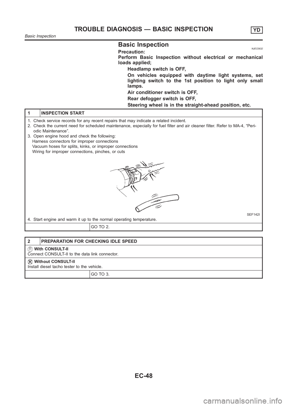
Basic InspectionNJEC0632Precaution:
Perform Basic Inspection without electrical or mechanical
loads applied;
Headlamp switch is OFF,
On vehicles equipped with daytime light systems, set
lighting switch to the 1st position to light only small
lamps.
Air conditioner switch is OFF,
Rear defogger switch is OFF,
Steering wheel is in the straight-ahead position, etc.
1 INSPECTION START
1. Check service records for any recent repairs that may indicate a relatedincident.
2. Check the current need for scheduled maintenance, especially for fuel filter and air cleaner filter. Refer to MA-4, “Peri-
odic Maintenance”.
3. Open engine hood and check the following:
Harness connectors for improper connections
Vacuum hoses for splits, kinks, or improper connections
Wiring for improper connections, pinches, or cuts
SEF142I
4. Start engine and warm it up to the normal operating temperature.
GO TO 2.
2 PREPARATION FOR CHECKING IDLE SPEED
With CONSULT-II
Connect CONSULT-II to the data link connector.
Without CONSULT-II
Install diesel tacho tester to the vehicle.
GO TO 3.
TROUBLE DIAGNOSIS — BASIC INSPECTIONYD
Basic Inspection
EC-48
Page 1461 of 3189

PRECAUTIONS
AT-5
D
E
F
G
H
I
J
K
L
MA
B
AT
PRECAUTIONSPFP:00001
Precautions for Supplemental Restraint System (SRS) “AIR BAG” and “SEAT
BELT PRE-TENSIONER”
ECS007N3
The Supplemental Restraint System such as “AIR BAG” and “SEAT BELT PRE-TENSIONER”, used along
with a front seat belt, helps to reduce the risk or severity of injury to the driver and front passenger for certain
types of collision. Information necessary to service the system safely is included in the SRS and SB section of
this Service Manual.
WARNING:
●To avoid rendering the SRS inoperative, which could increase the risk of personal injury or death
in the event of a collision which would result in air bag inflation, all maintenance must be per-
formed by an authorized NISSAN/INFINITI dealer.
●Improper maintenance, including incorrect removal and installation of the SRS, can lead to per-
sonal injury caused by unintentional activation of the system. For removal of Spiral Cable and Air
Bag Module, see the SRS section.
●Do not use electrical test equipment on any circuit related to the SRS unless instructed to in this
Service Manual. SRS wiring harnesses can be identified by yellow and/or orange harness connec-
tors.
Precautions for On Board Diagnostic (EURO-OBD) System of A/T and Engine —
Euro-OBD —
ECS007N4
The ECM has an on board diagnostic system. It will light up the malfunction indicator (MI) to warn the driver of
a malfunction causing emission deterioration.
CAUTION:
●Be sure to turn the ignition switch “OFF” and disconnect the negative battery terminal before any
repair or inspection work. The open/short circuit of related switches, sensors, solenoid valves,
etc. will cause the MI to light up.
●Be sure to connect and lock the connectors securely after work. A loose (unlocked) connector will
cause the MI to light up due to an open circuit. (Be sure the connector is free from water, grease,
dirt, bent terminals, etc.)
●Be sure to route and secure the harnesses properly after work. Interference of the harness with a
bracket, etc. may cause the MI to light up due to a short circuit.
●Be sure to connect rubber tubes properly after work. A misconnected or disconnected rubber tube
may cause the MI to light up due to a malfunction of the EGR system or fuel injection system, etc.
●Be sure to erase the unnecessary malfunction information (repairs completed) from the TCM and
ECM before returning the vehicle to the customer.
Precautions for Trouble DiagnosisECS007N5
CAN SYSTEM
●Do not apply voltage of 7.0V or higher to the measurement terminals.
●Use the tester with its open terminal voltage being 7.0V or less.
Precautions for Harness RepairECS007N6
CAN SYSTEM
●Solder the repaired parts, and wrap with tape. [Frays of twisted
line must be within 110 mm (4.33 in)]
PKIA0306E
Page 1981 of 3189

ATC-1
AUTOMATIC AIR CONDITIONER
J AIR CONDITIONER
CONTENTS
C
D
E
F
G
H
I
K
L
M
SECTION
A
B
AT C
AUTOMATIC AIR CONDITIONER
PRECAUTIONS .......................................................... 4
Precautions for Supplemental Restraint System
(SRS) “AIR BAG” and “SEAT BELT PRE-TEN-
SIONER” .................................................................. 4
Precautions for Working with HFC-134a (R-134a) ..... 4
General Refrigerant Precautions .............................. 4
Lubricant Precautions .............................................. 5
Precautions for Refrigerant Connection ................... 5
FEATURES OF NEW TYPE REFRIGERANT
CONNECTION ...................................................... 5
O-RING AND REFRIGERANT CONNECTION ..... 6
Precautions for Servicing Compressor ..................... 7
Precautions for Service Equipment .......................... 7
RECOVERY/RECYCLING EQUIPMENT .............. 7
ELECTRONIC LEAK DETECTOR ........................ 8
VACUUM PUMP ................................................... 8
MANIFOLD GAUGE SET ...................................... 8
SERVICE HOSES ................................................. 8
SERVICE COUPLERS .......................................... 9
REFRIGERANT WEIGHT SCALE ........................ 9
CALIBRATING ACR4 WEIGHT SCALE ................ 9
CHARGING CYLINDER ........................................ 9
Precautions for Leak Detection Dye ......................... 9
IDENTIFICATION ................................................ 10
IDENTIFICATION LABEL FOR VEHICLE ........... 10
Wiring Diagrams and Trouble Diagnosis ................ 10
PREPARATION ..........................................................11
Special Service Tools .............................................. 11
HFC-134a (R-134a) Service Tools and Equipment .... 11
REFRIGERATION SYSTEM ..................................... 15
Refrigerant Cycle ................................................... 15
REFRIGERANT FLOW ....................................... 15
FREEZE PROTECTION ..................................... 15
Refrigerant System Protection ............................... 15
REFRIGERANT PRESSURE SENSOR (WITH
GASOLINE ENGINE) .......................................... 15
DUAL-PRESSURE SWITCH (WITH DIESEL
ENGINE) ............................................................. 15
PRESSURE RELIEF VALVE ............................... 15
CSV613 Variable Displacement Compressor ......... 16GENERAL INFORMATION ................................. 16
DESCRIPTION .................................................... 16
Component Layout ................................................. 19
LUBRICANT .............................................................. 20
Maintenance of Lubricant Quantity in Compressor ... 20
LUBRICANT ........................................................ 20
LUBRICANT RETURN OPERATION .................. 20
LUBRICANT ADJUSTING PROCEDURE FOR
COMPONENTS REPLACEMENT EXCEPT
COMPRESSOR .................................................. 21
LUBRICANT ADJUSTING PROCEDURE FOR
COMPRESSOR REPLACEMENT ....................... 21
AIR CONDITIONER CONTROL ............................... 22
Overview Air Conditioner LAN Control System ...... 22
System Construction .............................................. 22
OPERATION ........................................................ 22
TRANSMISSION DATA AND TRANSMISSION
ORDER ............................................................... 23
AIR MIX DOOR CONTROL (AUTOMATIC TEM-
PERATURE CONTROL) ..................................... 23
FAN SPEED CONTROL ...................................... 24
INTAKE DOOR CONTROL ................................. 24
OUTLET DOOR CONTROL ................................ 24
MAGNET CLUTCH CONTROL ........................... 24
SELF-DIAGNOSTIC SYSTEM ............................ 24
Overview of Control system .................................... 24
Control Operation ................................................... 25
DISPLAY SCREEN .............................................. 25
AUTO SWITCH ................................................... 25
TEMPERATURE DIAL (POTENTIO TEMPERA-
TURE CONTROL) ............................................... 25
A/C SWITCH ....................................................... 25
DEFROSTER (DEF) SWITCH ............................. 25
MODE SWITCH .................................................. 25
FAN SWITCH ...................................................... 25
OFF SWITCH ...................................................... 25
FRESH (FRE) SWITCH ...................................... 25
RECIRCULATION (REC) SWITCH ..................... 26
REAR WINDOW DEFOGGER SWITCH ............. 26
Fail-safe Function ................................................... 26