2003 NISSAN ALMERA N16 maintenance
[x] Cancel search: maintenancePage 2796 of 3189
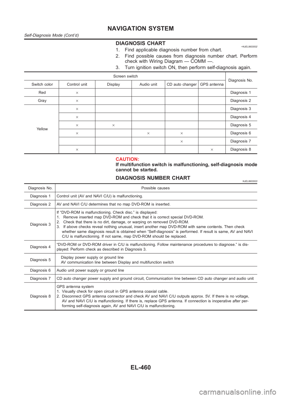
DIAGNOSIS CHART=NJEL0603S021. Find applicable diagnosis number from chart.
2. Find possible causes from diagnosis number chart. Perform
check with Wiring Diagram — COMM —.
3. Turn ignition switch ON, then perform self-diagnosis again.
Screen switch
Diagnosis No.
Switch color Control unit Display Audio unit CD auto changer GPS antenna
Red×Diagnosis 1
Gray×Diagnosis 2
Yellow×Diagnosis 3
×Diagnosis 4
××Diagnosis 5
×××Diagnosis 6
×Diagnosis 7
××Diagnosis 8
CAUTION:
If multifunction switch is malfunctioning, self-diagnosis mode
cannot be started.
DIAGNOSIS NUMBER CHARTNJEL0603S03
Diagnosis No. Possible causes
Diagnosis 1 Control unit (AV and NAVI C/U) is malfunctioning.
Diagnosis 2 AV and NAVI C/U determines that no map DVD-ROM is inserted.
Diagnosis 3If “DVD-ROM is malfunctioning. Check disc.” is displayed:
1. Remove inserted map DVD-ROM and check that it is correct special DVD-ROM.
2. Check that there is no dirt, damage, or warping on removed DVD-ROM.
3. If above checks reveal nothing unusual, insert another map DVD-ROM withsame contents. Then check
whether same diagnosis result is obtained when “Self-diagnosis” is performed. If result is same, AV and NAVI
C/U is malfunctioning. If not same, map DVD-ROM should be replaced.
Diagnosis 4“DVD-ROM or DVD-ROM driver in C/U is malfunctioning. Follow maintenance procedures to diagnose.” is dis-
played: Perform check as described in Diagnosis 3.
Diagnosis 5Display power supply or ground line
AV communication line between Display and multifunction switch
Diagnosis 6 Audio unit power supply or ground line
Diagnosis 7 CD auto changer power supply and ground circuit, Communication line between CD auto changer and audio unit
Diagnosis 8GPS antenna system
1. Visually check for open circuit in GPS antenna coaxial cable.
2. Disconnect GPS antenna connector and check AV and NAVI C/U outputs approx. 5V. If there is no voltage,
AV and NAVI C/U is malfunctioning. If there is, replace GPS antenna. If connection is inoperative after per-
forming self-diagnosis again, AV and NAVI C/U is malfunctioning.
NAVIGATION SYSTEM
Self-Diagnosis Mode (Cont’d)
EL-460
Page 2832 of 3189
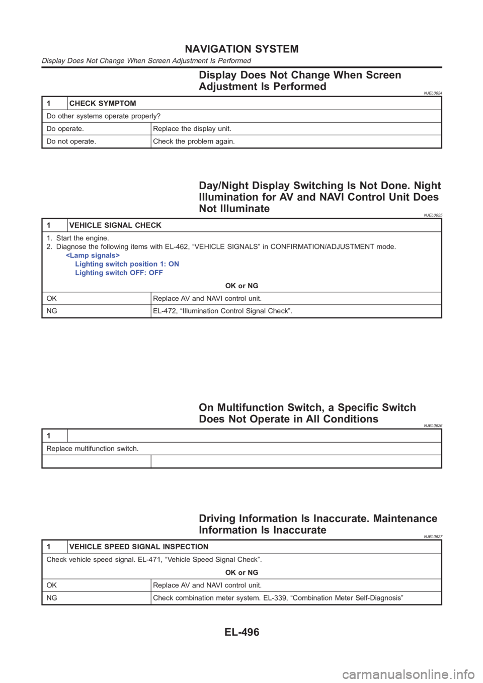
Display Does Not Change When Screen
Adjustment Is Performed
NJEL0624
1 CHECK SYMPTOM
Do other systems operate properly?
Do operate. Replace the display unit.
Do not operate. Check the problem again.
Day/Night Display Switching Is Not Done. Night
Illumination for AV and NAVI Control Unit Does
Not Illuminate
NJEL0625
1 VEHICLE SIGNAL CHECK
1. Start the engine.
2. Diagnose the following items with EL-462, “VEHICLE SIGNALS” in CONFIRMATION/ADJUSTMENT mode.
Lighting switch position 1: ON
Lighting switch OFF: OFF
OK or NG
OK Replace AV and NAVI control unit.
NG EL-472, “Illumination Control Signal Check”.
On Multifunction Switch, a Specific Switch
Does Not Operate in All Conditions
NJEL0626
1
Replace multifunction switch.
Driving Information Is Inaccurate. Maintenance
Information Is Inaccurate
NJEL0627
1 VEHICLE SPEED SIGNAL INSPECTION
Check vehicle speed signal. EL-471, “Vehicle Speed Signal Check”.
OK or NG
OK Replace AV and NAVI control unit.
NG Check combination meter system. EL-339, “Combination Meter Self-Diagnosis”
NAVIGATION SYSTEM
Display Does Not Change When Screen Adjustment Is Performed
EL-496
Page 2937 of 3189
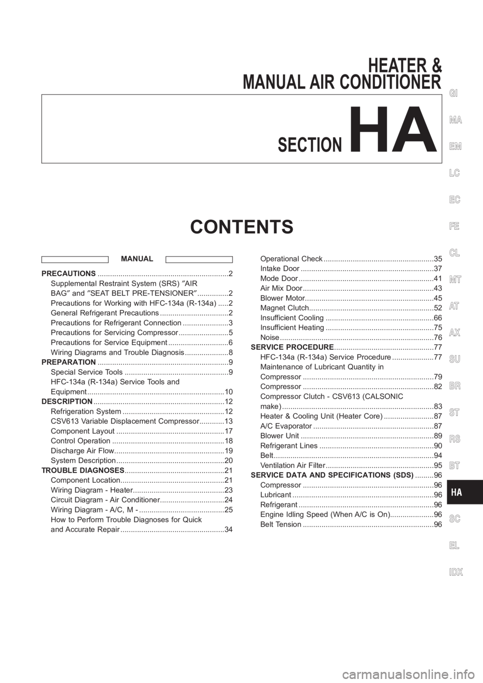
HEATER &
MANUAL AIR CONDITIONER
SECTION
HA
CONTENTS
MANUAL
PRECAUTIONS<0011001100110011001100110011001100110011001100110011001100110011001100110011001100110011001100110011001100110011001100110011001100110011001100110011001100110011001100110011001100110011001100110011001100
11001100110011001100110011001100110011001100110011[2
Supplemental Restraint System (SRS)″AIR
BAG″and″SEAT BELT PRE-TENSIONER″...............2
Precautions for Working with HFC-134a (R-134a) .....2
General Refrigerant Precautions .................................2
Precautions for Refrigerant Connection ......................3
Precautions for Servicing Compressor ........................5
Precautions for Service Equipment .............................6
Wiring Diagrams and Trouble Diagnosis .....................8
PREPARATION<0011001100110011001100110011001100110011001100110011001100110011001100110011001100110011001100110011001100110011001100110011001100110011001100110011001100110011001100110011001100110011001100110011001100
11001100110011001100110011001100110011001100110011[9
Special Service Tools ..................................................9
HFC-134a (R-134a) Service Tools and
Equipment <0011001100110011001100110011001100110011001100110011001100110011001100110011001100110011001100110011001100110011001100110011001100110011001100110011001100110011001100110011001100110011001100110011001100
11001100110011[............10
DESCRIPTION<0011001100110011001100110011001100110011001100110011001100110011001100110011001100110011001100110011001100110011001100110011001100110011001100110011001100110011001100110011001100110011001100110011001100
11001100110011001100110011001100110011001100110011[12
Refrigeration System .................................................12
CSV613 Variable Displacement Compressor............13
Component Layout ....................................................17
Control Operation ......................................................18
Discharge Air Flow.....................................................19
System Description ....................................................20
TROUBLE DIAGNOSES................................................21
Component Location..................................................21
Wiring Diagram - Heater............................................23
Circuit Diagram - Air Conditioner...............................24
Wiring Diagram - A/C, M - .........................................25
How to Perform Trouble Diagnoses for Quick
and Accurate Repair ..................................................34Operational Check .....................................................35
Intake Door <0011001100110011001100110011001100110011001100110011001100110011001100110011001100110011001100110011001100110011001100110011001100110011001100110011001100110011001100110011001100110011001100110011001100
1100110011[...........37
Mode Door <0011001100110011001100110011001100110011001100110011001100110011001100110011001100110011001100110011001100110011001100110011001100110011001100110011001100110011001100110011001100110011001100110011001100
110011001100110011[..........41
Air Mix Door <0011001100110011001100110011001100110011001100110011001100110011001100110011001100110011001100110011001100110011001100110011001100110011001100110011001100110011001100110011001100110011001100110011001100
1100110011[..........43
Blower Motor<0011001100110011001100110011001100110011001100110011001100110011001100110011001100110011001100110011001100110011001100110011001100110011001100110011001100110011001100110011001100110011001100110011001100
110011[..........45
Magnet Clutch<0011001100110011001100110011001100110011001100110011001100110011001100110011001100110011001100110011001100110011001100110011001100110011001100110011001100110011001100110011001100110011001100110011001100
11[.........52
Insufficient Cooling ....................................................66
Insufficient Heating ....................................................75
Noise <0011001100110011001100110011001100110011001100110011001100110011001100110011001100110011001100110011001100110011001100110011001100110011001100110011001100110011001100110011001100110011001100110011001100
110011001100110011001100110011[................76
SERVICE PROCEDURE................................................77
HFC-134a (R-134a) Service Procedure ....................77
Maintenance of Lubricant Quantity in
Compressor <0011001100110011001100110011001100110011001100110011001100110011001100110011001100110011001100110011001100110011001100110011001100110011001100110011001100110011001100110011001100110011001100110011001100
1100110011[..........79
Compressor <0011001100110011001100110011001100110011001100110011001100110011001100110011001100110011001100110011001100110011001100110011001100110011001100110011001100110011001100110011001100110011001100110011001100
1100110011[..........82
Compressor Clutch - CSV613 (CALSONIC
make) <0011001100110011001100110011001100110011001100110011001100110011001100110011001100110011001100110011001100110011001100110011001100110011001100110011001100110011001100110011001100110011001100110011001100
110011001100110011001100110011[...............83
Heater & Cooling Unit (Heater Core) ........................87
A/C Evaporator ..........................................................87
Blower Unit <0011001100110011001100110011001100110011001100110011001100110011001100110011001100110011001100110011001100110011001100110011001100110011001100110011001100110011001100110011001100110011001100110011001100
1100110011[...........89
Refrigerant Lines .......................................................90
Belt <0011001100110011001100110011001100110011001100110011001100110011001100110011001100110011001100110011001100110011001100110011001100110011001100110011001100110011001100110011001100110011001100110011001100
1100110011001100110011001100110011[..................94
Ventilation Air Filter ....................................................95
SERVICE DATA AND SPECIFICATIONS (SDS).........96
Compressor <0011001100110011001100110011001100110011001100110011001100110011001100110011001100110011001100110011001100110011001100110011001100110011001100110011001100110011001100110011001100110011001100110011001100
1100110011[..........96
Lubricant <0011001100110011001100110011001100110011001100110011001100110011001100110011001100110011001100110011001100110011001100110011001100110011001100110011001100110011001100110011001100110011001100110011001100
11001100110011[..............96
Refrigerant <0011001100110011001100110011001100110011001100110011001100110011001100110011001100110011001100110011001100110011001100110011001100110011001100110011001100110011001100110011001100110011001100110011001100
110011[.............96
Engine Idling Speed (When A/C is On).....................96
Belt Tension <0011001100110011001100110011001100110011001100110011001100110011001100110011001100110011001100110011001100110011001100110011001100110011001100110011001100110011001100110011001100110011001100110011001100
110011[...........96
GI
MA
EM
LC
EC
FE
CL
MT
AT
AX
SU
BR
ST
RS
BT
SC
EL
IDX
Page 2938 of 3189
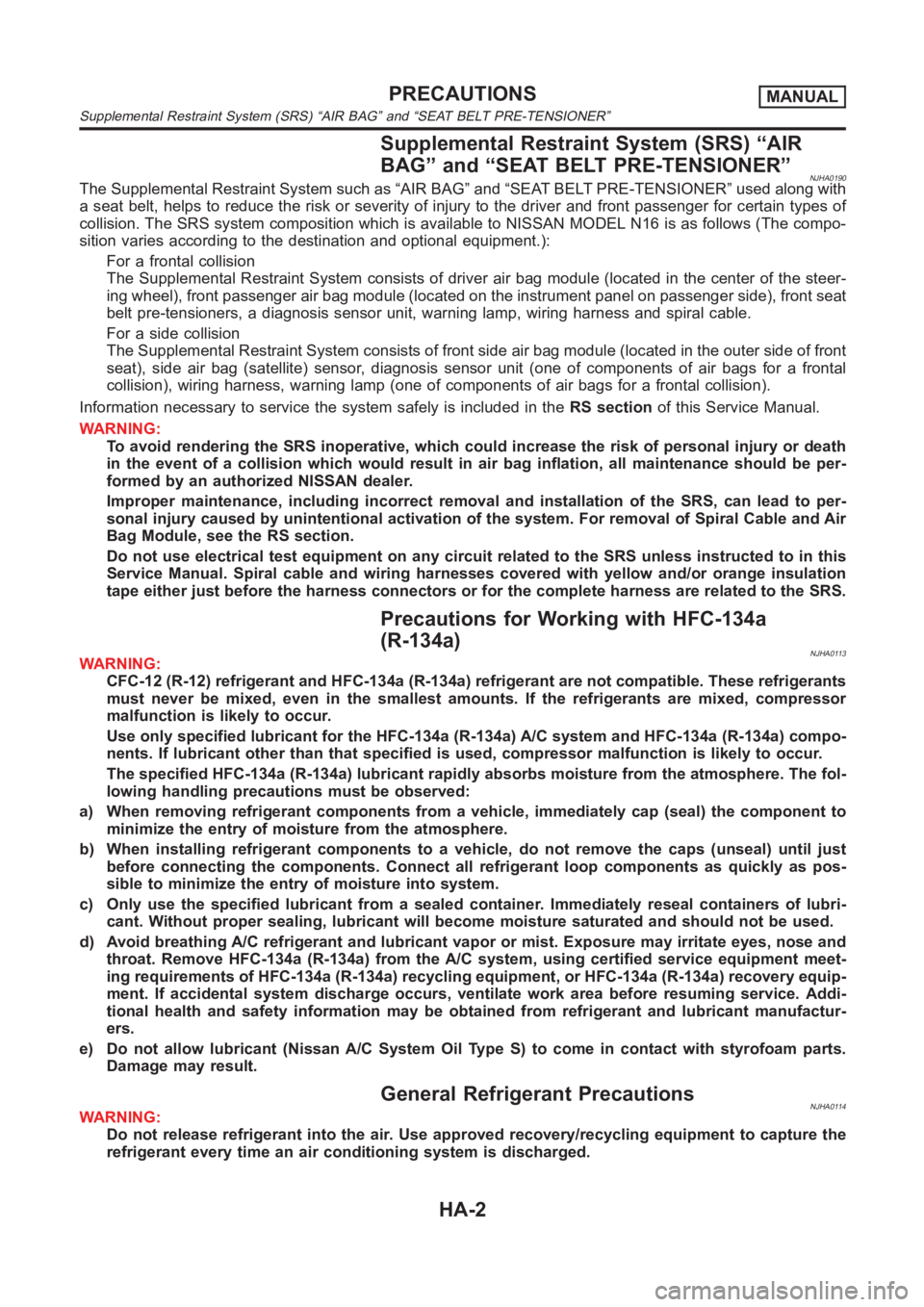
Supplemental Restraint System (SRS) “AIR
BAG” and “SEAT BELT PRE-TENSIONER”
NJHA0190The Supplemental Restraint System such as “AIR BAG” and “SEAT BELT PRE-TENSIONER” used along with
a seat belt, helps to reduce the risk or severity of injury to the driver and front passenger for certain types of
collision. The SRS system composition which is available to NISSAN MODEL N16 is as follows (The compo-
sition varies according to the destination and optional equipment.):
For a frontal collision
The Supplemental Restraint System consists of driver air bag module (located in the center of the steer-
ing wheel), front passenger air bag module (located on the instrument panel on passenger side), front seat
belt pre-tensioners, a diagnosis sensor unit, warning lamp, wiring harness and spiral cable.
For a side collision
The Supplemental Restraint System consists of front side air bag module (located in the outer side of front
seat), side air bag (satellite) sensor, diagnosis sensor unit (one of components of air bags for a frontal
collision), wiring harness, warning lamp (one of components of air bags for a frontal collision).
Information necessary to service the system safely is included in theRS sectionof this Service Manual.
WARNING:
To avoid rendering the SRS inoperative, which could increase the risk of personal injury or death
in the event of a collision which would result in air bag inflation, all maintenance should be per-
formed by an authorized NISSAN dealer.
Improper maintenance, including incorrect removal and installation of the SRS, can lead to per-
sonal injury caused by unintentional activation of the system. For removalofSpiralCableandAir
Bag Module, see the RS section.
Do not use electrical test equipment on any circuit related to the SRS unless instructed to in this
Service Manual. Spiral cable and wiring harnesses covered with yellow and/or orange insulation
tape either just before the harness connectors or for the complete harnessare related to the SRS.
Precautions for Working with HFC-134a
(R-134a)
NJHA0113WARNING:
CFC-12 (R-12) refrigerant and HFC-134a (R-134a) refrigerant are not compatible. These refrigerants
must never be mixed, even in the smallest amounts. If the refrigerants are mixed, compressor
malfunction is likely to occur.
Use only specified lubricant for the HFC-134a (R-134a) A/C system and HFC-134a (R-134a) compo-
nents. If lubricant other than that specified is used, compressor malfunction is likely to occur.
The specified HFC-134a (R-134a) lubricant rapidly absorbs moisture fromthe atmosphere. The fol-
lowing handling precautions must be observed:
a) When removing refrigerant components from a vehicle, immediately cap (seal) the component to
minimize the entry of moisture from the atmosphere.
b) When installing refrigerant components to a vehicle, do not remove the caps (unseal) until just
before connecting the components. Connect all refrigerant loop components as quickly as pos-
sible to minimize the entry of moisture into system.
c) Only use the specified lubricant from a sealed container. Immediately reseal containers of lubri-
cant. Without proper sealing, lubricant will become moisture saturated and should not be used.
d) Avoid breathing A/C refrigerant and lubricant vapor or mist. Exposure may irritate eyes, nose and
throat. Remove HFC-134a (R-134a) from the A/C system, using certified service equipment meet-
ing requirements of HFC-134a (R-134a) recycling equipment, or HFC-134a (R-134a) recovery equip-
ment. If accidental system discharge occurs, ventilate work area before resuming service. Addi-
tional health and safety information may be obtained from refrigerant andlubricant manufactur-
ers.
e) Do not allow lubricant (Nissan A/C System Oil Type S) to come in contact with styrofoam parts.
Damage may result.
General Refrigerant PrecautionsNJHA0114WARNING:
Do not release refrigerant into the air. Use approved recovery/recyclingequipment to capture the
refrigerant every time an air conditioning system is discharged.
PRECAUTIONSMANUAL
Supplemental Restraint System (SRS) “AIR BAG” and “SEAT BELT PRE-TENSIONER”
HA-2
Page 2941 of 3189
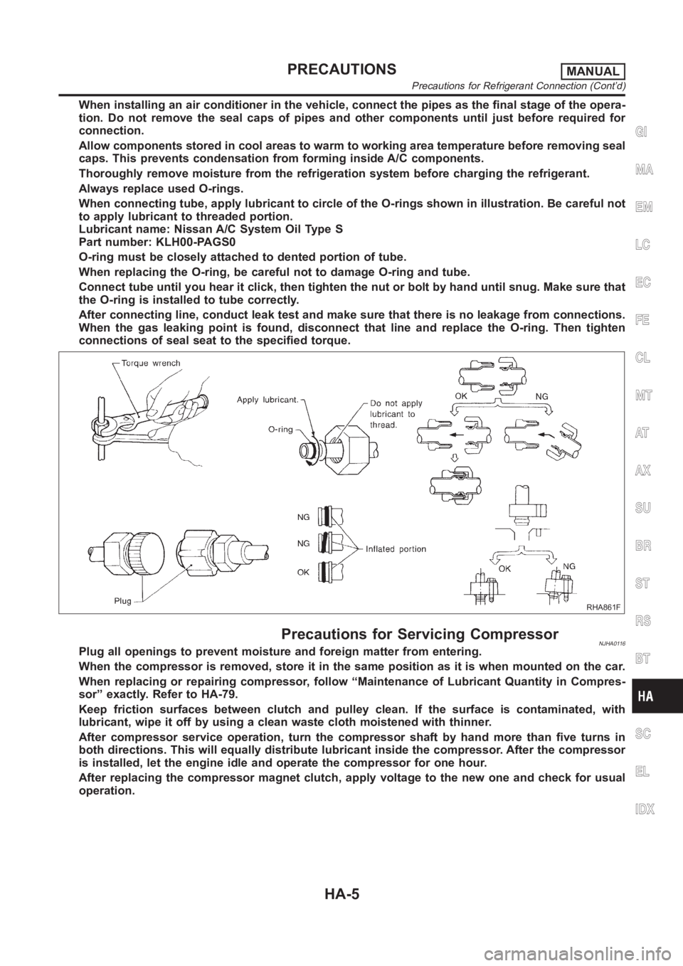
When installing an air conditioner in the vehicle, connect the pipes as thefinal stage of the opera-
tion. Do not remove the seal caps of pipes and other components until just before required for
connection.
Allow components stored in cool areas to warm to working area temperature before removing seal
caps. This prevents condensation from forming inside A/C components.
Thoroughly remove moisture from the refrigeration system before charging the refrigerant.
Always replace used O-rings.
When connecting tube, apply lubricant to circle of the O-rings shown in illustration. Be careful not
to apply lubricant to threaded portion.
Lubricant name: Nissan A/C System Oil Type S
Part number: KLH00-PAGS0
O-ring must be closely attached to dented portion of tube.
When replacing the O-ring, be careful not to damage O-ring and tube.
Connect tube until you hear it click, then tighten the nut or bolt by hand until snug. Make sure that
the O-ring is installed to tube correctly.
After connecting line, conduct leak test and make sure that there is no leakage from connections.
When the gas leaking point is found, disconnect that line and replace the O-ring. Then tighten
connections of seal seat to the specified torque.
RHA861F
Precautions for Servicing CompressorNJHA0116Plug all openings to prevent moisture and foreign matter from entering.
When the compressor is removed, store it in the same position as it is when mounted on the car.
When replacing or repairing compressor, follow “Maintenance of Lubricant Quantity in Compres-
sor” exactly. Refer to HA-79.
Keep friction surfaces between clutch and pulley clean. If the surface is contaminated, with
lubricant, wipe it off by using a clean waste cloth moistened with thinner.
After compressor service operation, turn the compressor shaft by hand more than five turns in
both directions. This will equally distribute lubricant inside the compressor. After the compressor
is installed, let the engine idle and operate the compressor for one hour.
After replacing the compressor magnet clutch, apply voltage to the new oneand check for usual
operation.
GI
MA
EM
LC
EC
FE
CL
MT
AT
AX
SU
BR
ST
RS
BT
SC
EL
IDX
PRECAUTIONSMANUAL
Precautions for Refrigerant Connection (Cont’d)
HA-5
Page 2942 of 3189
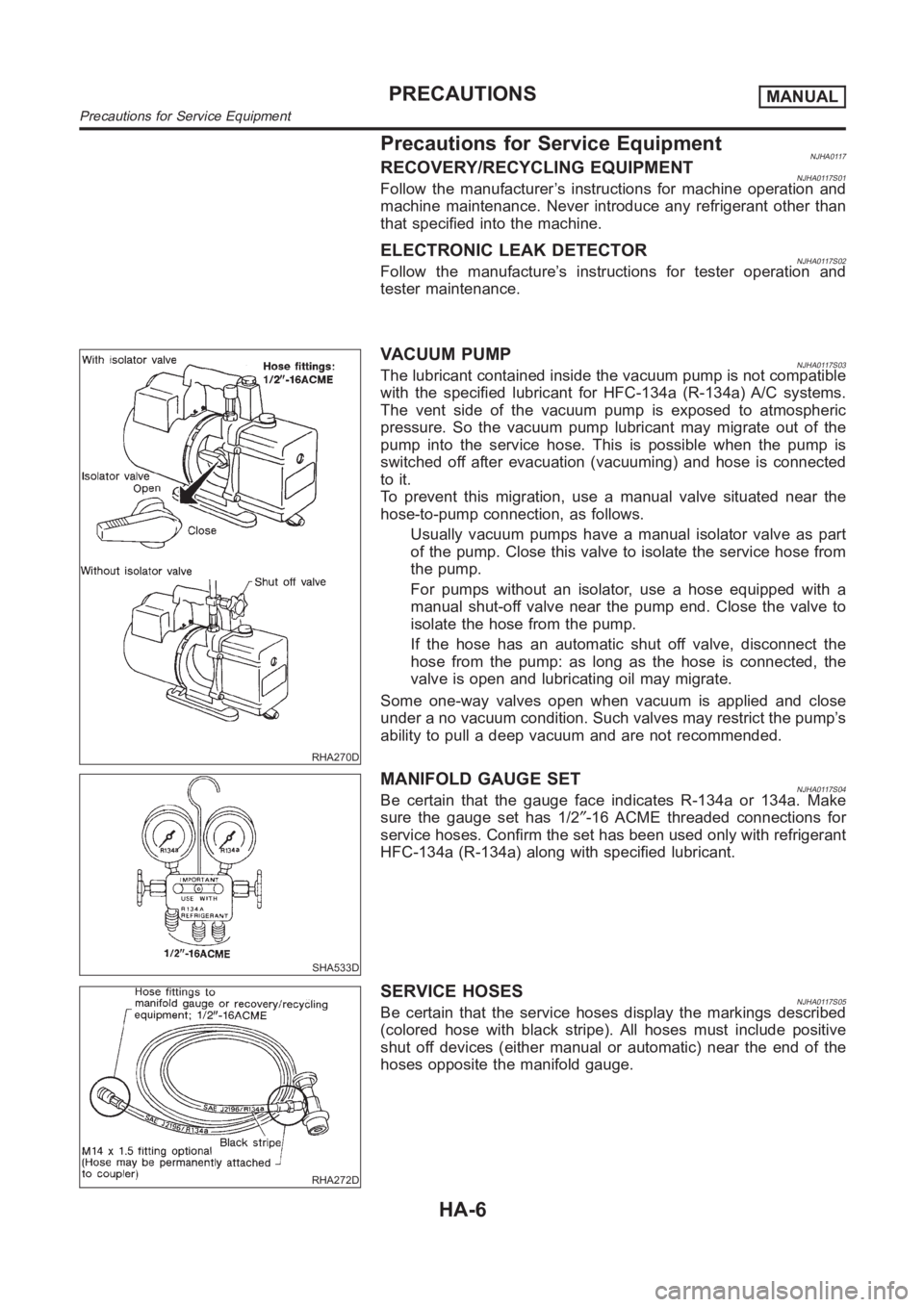
Precautions for Service EquipmentNJHA0117RECOVERY/RECYCLING EQUIPMENTNJHA0117S01Follow the manufacturer’s instructions for machine operation and
machine maintenance. Never introduce any refrigerant other than
that specified into the machine.
ELECTRONIC LEAK DETECTORNJHA0117S02Follow the manufacture’s instructions for tester operation and
tester maintenance.
RHA270D
VACUUM PUMPNJHA0117S03The lubricant contained inside the vacuum pump is not compatible
with the specified lubricant for HFC-134a (R-134a) A/C systems.
The vent side of the vacuum pump is exposed to atmospheric
pressure. So the vacuum pump lubricant may migrate out of the
pump into the service hose. This is possible when the pump is
switched off after evacuation (vacuuming) and hose is connected
to it.
To prevent this migration, use a manual valve situated near the
hose-to-pump connection, as follows.
Usually vacuum pumps have a manual isolator valve as part
of the pump. Close this valve to isolate the service hose from
the pump.
For pumps without an isolator, use a hose equipped with a
manual shut-off valve near the pump end. Close the valve to
isolate the hose from the pump.
If the hose has an automatic shut off valve, disconnect the
hose from the pump: as long as the hose is connected, the
valve is open and lubricating oil may migrate.
Some one-way valves open when vacuum is applied and close
under a no vacuum condition. Such valves may restrict the pump’s
ability to pull a deep vacuum and are not recommended.
SHA533D
MANIFOLD GAUGE SETNJHA0117S04Be certain that the gauge face indicates R-134a or 134a. Make
sure the gauge set has 1/2″-16 ACME threaded connections for
service hoses. Confirm the set has been used only with refrigerant
HFC-134a (R-134a) along with specified lubricant.
RHA272D
SERVICE HOSESNJHA0117S05Be certain that the service hoses display the markings described
(colored hose with black stripe). All hoses must include positive
shut off devices (either manual or automatic) near the end of the
hoses opposite the manifold gauge.
PRECAUTIONSMANUAL
Precautions for Service Equipment
HA-6
Page 3015 of 3189
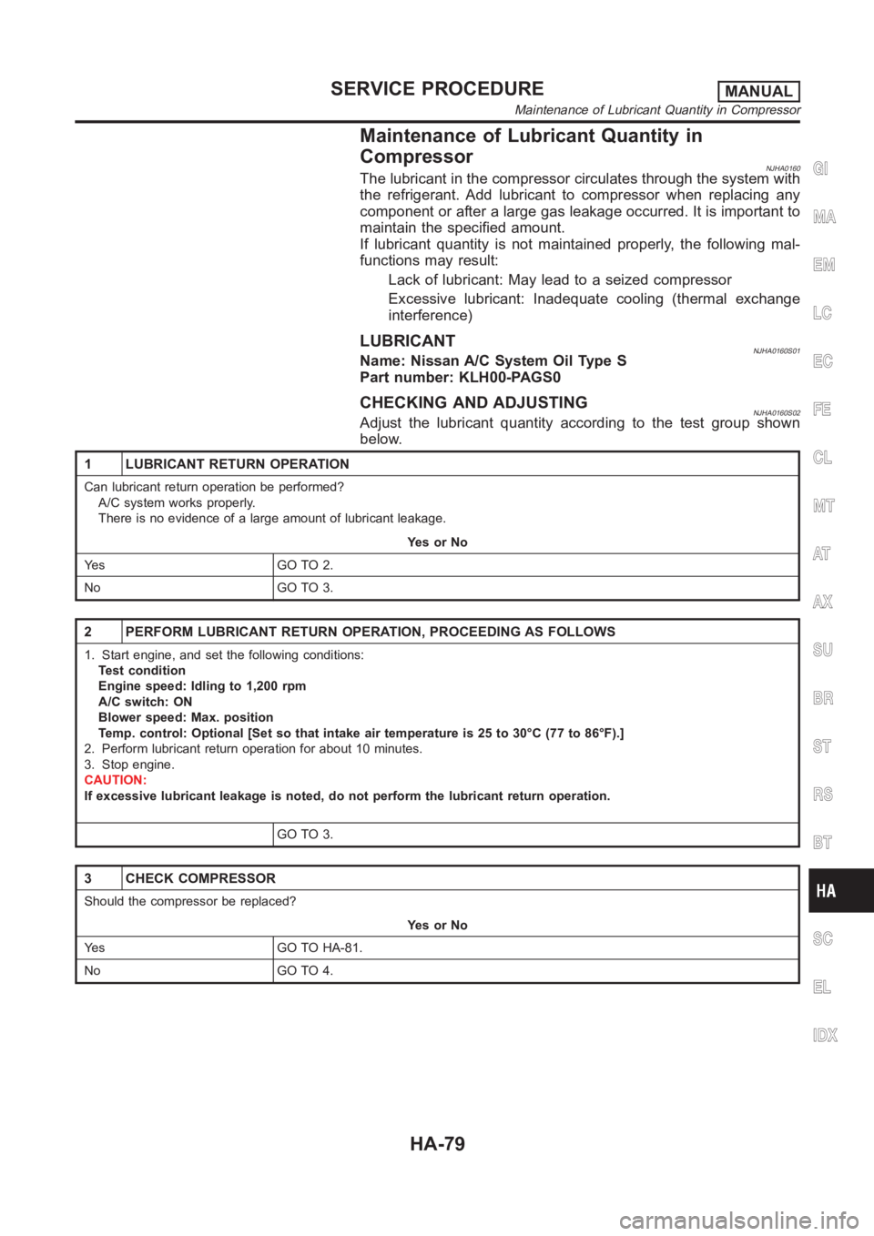
Maintenance of Lubricant Quantity in
Compressor
NJHA0160The lubricant in the compressor circulates through the system with
the refrigerant. Add lubricant to compressor when replacing any
component or after a large gas leakage occurred. It is important to
maintain the specified amount.
If lubricant quantity is not maintained properly, the following mal-
functions may result:
Lack of lubricant: May lead to a seized compressor
Excessive lubricant: Inadequate cooling (thermal exchange
interference)
LUBRICANTNJHA0160S01Name: Nissan A/C System Oil Type S
Part number: KLH00-PAGS0
CHECKING AND ADJUSTINGNJHA0160S02Adjust the lubricant quantity according to the test group shown
below.
1 LUBRICANT RETURN OPERATION
Can lubricant return operation be performed?
A/C system works properly.
There is no evidence of a large amount of lubricant leakage.
YesorNo
Ye s G O T O 2 .
No GO TO 3.
2 PERFORM LUBRICANT RETURN OPERATION, PROCEEDING AS FOLLOWS
1. Start engine, and set the following conditions:
Test condition
Engine speed: Idling to 1,200 rpm
A/C switch: ON
Blower speed: Max. position
Temp. control: Optional [Set so that intake air temperature is 25 to 30°C (77 to 86°F).]
2. Perform lubricant return operation for about 10 minutes.
3. Stop engine.
CAUTION:
If excessive lubricant leakage is noted, do not perform the lubricant return operation.
GO TO 3.
3 CHECK COMPRESSOR
Should the compressor be replaced?
YesorNo
Yes GO TO HA-81.
No GO TO 4.
GI
MA
EM
LC
EC
FE
CL
MT
AT
AX
SU
BR
ST
RS
BT
SC
EL
IDX
SERVICE PROCEDUREMANUAL
Maintenance of Lubricant Quantity in Compressor
HA-79
Page 3016 of 3189
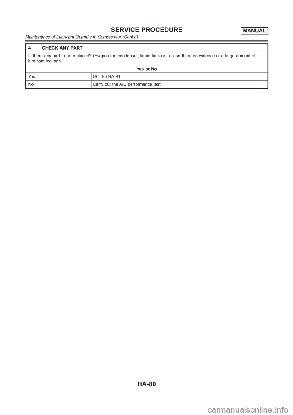
4 CHECK ANY PART
Is there any part to be replaced? (Evaporator, condenser, liquid tank or incase there is evidence of a large amount of
lubricant leakage.)
YesorNo
Yes GO TO HA-81.
No Carry out the A/C performance test.
SERVICE PROCEDUREMANUAL
Maintenance of Lubricant Quantity in Compressor (Cont’d)
HA-80