2003 NISSAN ALMERA N16 fuse block
[x] Cancel search: fuse blockPage 1260 of 3189
Diagnostic ProcedureNJEC0770
1 CHECK START SIGNAL OVERALL FUNCTION
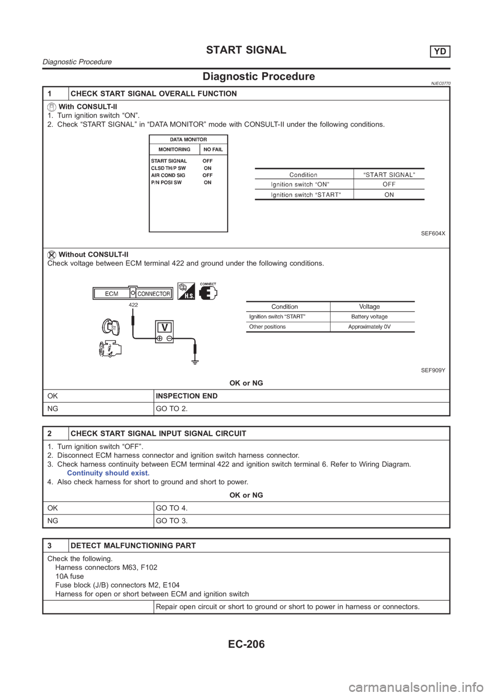
With CONSULT-II
1. Turn ignition switch “ON”.
2. Check “START SIGNAL” in “DATA MONITOR” mode with CONSULT-II under the following conditions.
SEF604X
Without CONSULT-II
Check voltage between ECM terminal 422 and ground under the following conditions.
SEF909Y
OK or NG
OKINSPECTION END
NG GO TO 2.
2 CHECK START SIGNAL INPUT SIGNAL CIRCUIT
1. Turn ignition switch “OFF”.
2. Disconnect ECM harness connector and ignition switch harness connector.
3. Check harness continuity between ECM terminal 422 and ignition switch terminal 6. Refer to Wiring Diagram.
Continuity should exist.
4. Also check harness for short to ground and short to power.
OK or NG
OK GO TO 4.
NG GO TO 3.
3 DETECT MALFUNCTIONING PART
Check the following.
Harness connectors M63, F102
10A fuse
Fuse block (J/B) connectors M2, E104
Harness for open or short between ECM and ignition switch
Repair open circuit or short to ground or short to power in harness or connectors.
START SIGNALYD
Diagnostic Procedure
EC-206
Page 2036 of 3189
ATC-56
TROUBLE DIAGNOSIS
DIAGNOSTIC PROCEDURE FOR A/C SYSTEM
SYMPTOM: A/C system does not come on.
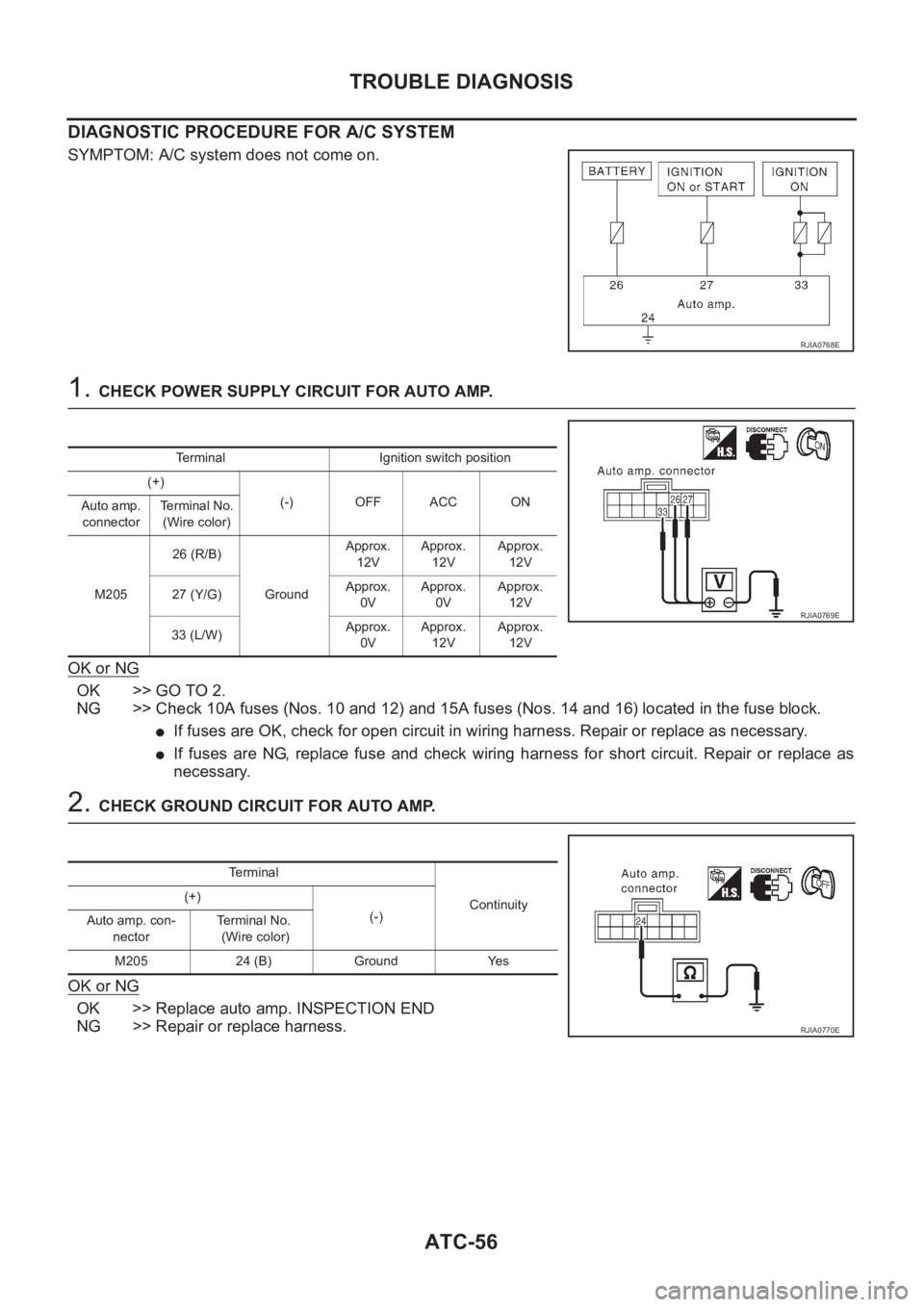
1. CHECK POWER SUPPLY CIRCUIT FOR AUTO AMP.
OK or NG
OK >> GO TO 2.
NG >> Check 10A fuses (Nos. 10 and 12) and 15A fuses (Nos. 14 and 16) located in the fuse block.
●If fuses are OK, check for open circuit in wiring harness. Repair or replace as necessary.
●If fuses are NG, replace fuse and check wiring harness for short circuit. Repair or replace as
necessary.
2. CHECK GROUND CIRCUIT FOR AUTO AMP.
OK or NG
OK >> Replace auto amp. INSPECTION END
NG >> Repair or replace harness.
RJIA0768E
Terminal Ignition switch position
(+)
(-) OFF ACC ON
Auto amp.
connectorTerminal No.
(Wire color)
M20526 (R/B)
GroundApprox.
12VApprox.
12VApprox.
12V
27 (Y/G)Approx.
0VApprox.
0VApprox.
12V
33 (L/W)Approx.
0VApprox.
12VApprox.
12V
RJIA0769E
Terminal
Continuity (+)
(-)
Auto amp. con-
nectorTe r m i n a l N o .
(Wire color)
M205 24 (B) Ground Yes
RJIA0770E
Page 2052 of 3189
ATC-72
TROUBLE DIAGNOSIS
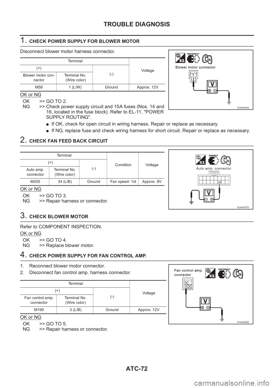
1. CHECK POWER SUPPLY FOR BLOWER MOTOR
Disconnect blower motor harness connector.
OK or NG
OK >> GO TO 2.
NG >> Check power supply circuit and 15A fuses (Nos. 14 and
16, located in the fuse block). Refer to EL-11, "POWER
SUPPLY ROUTING".
●If OK, check for open circuit in wiring harness. Repair or replace as necessary.
●If NG, replace fuse and check wiring harness for short circuit. Repair or replace as necessary.
2. CHECK FAN FEED BACK CIRCUIT
OK or NG
OK >> GO TO 3.
NG >> Repair harness or connector.
3. CHECK BLOWER MOTOR
Refer to COMPONENT INSPECTION.
OK or NG
OK >> GO TO 4.
NG >> Replace blower motor.
4. CHECK POWER SUPPLY FOR FAN CONTROL AMP.
1. Reconnect blower motor connector.
2. Disconnect fan control amp. harness connector.
OK or NG
OK >> GO TO 5.
NG >> Repair harness or connector.
Terminal
Vo l ta g e (+)
(-)
Blower motor con-
nectorTerminal No.
(Wire color)
M59 1 (L/W) Ground Approx. 12V
RJIA0524E
Te r m i n a l
Condition Voltage (+)
(-)
Auto amp.
connectorTerminal No.
(Wire color)
M205 34 (L/B) Ground Fan speed: 1st Approx. 8V
RJIA0787E
Te r m i n a l
Voltag e (+)
(-)
Fan control amp.
connectorTerminal No.
(Wire color)
M190 3 (L/B) Ground Approx. 12V
RJIA0526E
Page 2057 of 3189
TROUBLE DIAGNOSIS
ATC-77
C
D
E
F
G
H
I
K
L
MA
B
AT C
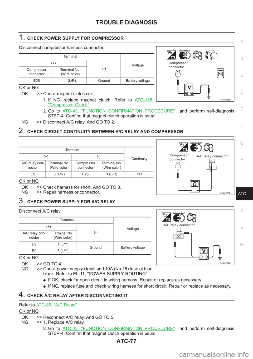
1.CHECK POWER SUPPLY FOR COMPRESSOR
Disconnect compressor harness connector.
OK or NG
OK >> Check magnet clutch coil.
1. If NG, replace magnet clutch. Refer to ATC-138,
"Compressor Clutch" .
2. Go to AT C - 4 3 , "
FUNCTION CONFIRMATION PROCEDURE" and perform self-diagnosis
STEP-4. Confirm that magnet clutch operation is usual.
NG >> Disconnect A/C relay. And GO TO 2.
2.CHECK CIRCUIT CONTINUITY BETWEEN A/C RELAY AND COMPRESSOR
OK or NG
OK >> Check harness for short. And GO TO 3.
NG >> Repair harness or connector.
3.CHECK POWER SUPPLY FOR A/C RELAY
Disconnect A/C relay.
OK or NG
OK >> GO TO 4.
NG >> Check power supply circuit and 10A (No.15) fuse at fuse
block. Refer to EL-11, "POWER SUPPLY ROUTING" .
●If OK, check for open circuit in wiring harness. Repair or replace as necessary.
●If NG, replace fuse and check wiring harness for short circuit. Repair or replace as necessary.
4.CHECK A/C RELAY AFTER DISCONNECTING IT
Refer to ATC-85, "
A/C Relay" .
OK or NG
OK >> Reconnect A/C relay. And GO TO 5.
NG >> 1. Replace A/C relay.
2. Go to AT C - 4 3 , "
FUNCTION CONFIRMATION PROCEDURE" and perform self-diagnosis
STEP-4. Confirm that magnet clutch operation is usual.
Terminal
Vo lta g e (+)
(-)
Compressor
connectorTe r m i n a l N o .
(Wire color)
E25 1 (L/R) Ground Battery voltage
RJIA0295E
Terminal
Continuity (+) (-)
A/C relay con-
nectorTerminal No.
(Wire color)Compressor
connectorTerminal No.
(Wire color)
E9 3 (L/R) E25 1 (L/R) Yes
RJIA0793E
Terminal
Vo l ta g e (+)
(-)
A/C relay con-
nectorTerminal No.
(Wire color)
E9 1 (L/Y)
Ground Battery voltage
E9 5 (L/Y)
RJIA0794E
Page 2062 of 3189
ATC-82
TROUBLE DIAGNOSIS
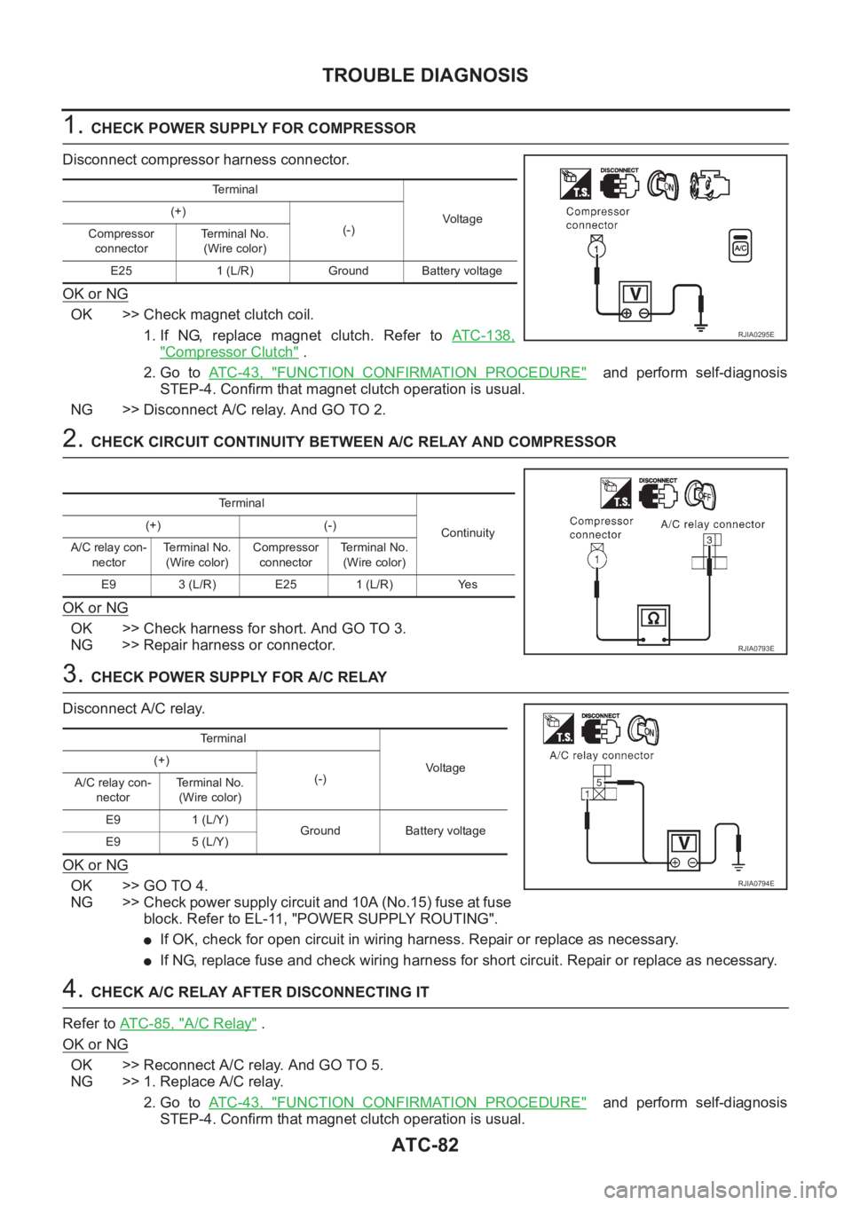
1. CHECK POWER SUPPLY FOR COMPRESSOR
Disconnect compressor harness connector.
OK or NG
OK >> Check magnet clutch coil.
1. If NG, replace magnet clutch. Refer to ATC-138,
"Compressor Clutch" .
2. Go to AT C - 4 3 , "
FUNCTION CONFIRMATION PROCEDURE" and perform self-diagnosis
STEP-4. Confirm that magnet clutch operation is usual.
NG >> Disconnect A/C relay. And GO TO 2.
2. CHECK CIRCUIT CONTINUITY BETWEEN A/C RELAY AND COMPRESSOR
OK or NG
OK >> Check harness for short. And GO TO 3.
NG >> Repair harness or connector.
3. CHECK POWER SUPPLY FOR A/C RELAY
Disconnect A/C relay.
OK or NG
OK >> GO TO 4.
NG >> Check power supply circuit and 10A (No.15) fuse at fuse
block. Refer to EL-11, "POWER SUPPLY ROUTING".
●If OK, check for open circuit in wiring harness. Repair or replace as necessary.
●If NG, replace fuse and check wiring harness for short circuit. Repair or replace as necessary.
4. CHECK A/C RELAY AFTER DISCONNECTING IT
Refer to AT C - 8 5 , "
A/C Relay" .
OK or NG
OK >> Reconnect A/C relay. And GO TO 5.
NG >> 1. Replace A/C relay.
2. Go to AT C - 4 3 , "
FUNCTION CONFIRMATION PROCEDURE" and perform self-diagnosis
STEP-4. Confirm that magnet clutch operation is usual.
Te r m i n a l
Voltag e (+)
(-)
Compressor
connectorTerminal No.
(Wire color)
E25 1 (L/R) Ground Battery voltage
RJIA0295E
Terminal
Continuity (+) (-)
A/C relay con-
nectorTerminal No.
(Wire color)Compressor
connectorTe r m i n a l N o .
(Wire color)
E9 3 (L/R) E25 1 (L/R) Yes
RJIA0793E
Te r m i n a l
Voltage (+)
(-)
A/C relay con-
nectorTerminal No.
(Wire color)
E9 1 (L/Y)
Ground Battery voltage
E9 5 (L/Y)
RJIA0794E
Page 2382 of 3189
System DescriptionNJEL0351The headlamp system on vehicles for cold spec. option contains a daytime light unit. The unit activates the
following whenever the engine is running with the lighting switch in the OFF position:
Low beam headlamps
Parking, license, tail and illumination lamps
Power is supplied at all times
through 10A fuse (No. 38, located in the fusible link and fuse box)
to daytime light unit terminal 1 and
to lighting switch terminal 11.
Power is also supplied at all times
through 15A fuse (No. 36, located in the fusible link and fuse box)
to daytime light unit terminal 3 and
to lighting switch terminal 5.
Power is also supplied at all times
through 15A fuse (No. 35, located in the fusible link and fuse box)
to daytime light unit terminal 2 and
to lighting switch terminal 8.
With the ignition switch in the ON or START position, power is supplied
through 10A fuse [No. 20, located in the fuse block (J/B)]
to daytime light unit terminal 7.
With the ignition switch in the START position, power is supplied
through 10A fuse [No. 21, located in the fuse block (J/B)]
to daytime light unit terminal 6.
Ground is supplied to daytime light unit terminal 9 through body grounds E30 and E73.
HEADLAMP OPERATION (DAYTIME LIGHT CANCEL OPERATION)NJEL0351S01When the lighting switch is turned to the 1st or 2nd position, power is supplied
through lighting switch terminal 12,
to daytime light unit terminal 11.
Then daytime light will be canceled. And the lighting system operation will be the same as no daytime light
system.
DAYTIME LIGHT OPERATIONNJEL0351S02With the engine running and the lighting switch in the OFF position, power is supplied
from alternator terminal 3
to daytime light unit terminal 8,
through daytime light unit terminal 5
to terminal 4 of headlamp LH,
through daytime light unit terminal 4
to terminal 2 of headlamp RH and
through daytime light unit terminal 10
to tail lamp and illumination.
Ground is supplied to terminal 5 of headlamp LH and terminal 1 of headlamp RHthrough body grounds E30
and E73.
HEADLAMP — DAYTIME LIGHT SYSTEM —
System Description
EL-46
Page 2403 of 3189
System Description/QG Engine Models and YD
Engine Models with Common Rail
NJEL0430TURN SIGNAL OPERATIONNJEL0430S01The turn signal lamps operation is controlled by the lighting switch whichis built into the combination switch
and smart entrance control unit.
Power is supplied at all times
through 15A fuse [No. 5, located in fuse block (J/B)]
to smart entrance control unit terminal 56
With the ignition switch in the ON or START position, power is supplied
through 10A fuse [No. 10, located in fuse block (J/B)]
to smart entrance control unit terminal 29
Ground is supplied to smart entrance control unit terminal 53 through bodygrounds F118 (QG engine models),
M28 and M67.
LH TurnNJEL0430S0101When the turn signal switch is moved to the L position, ground is supplied from body grounds E30 and E73
to
smart entrance control unit terminal 25
through turn signal switch terminal 3
With ground is supplied, smart entrance control unit controls the flashing of the LH turn signal lamps.
Power is supplied from smart entrance control unit terminal 64
to front turn signal lamp LH terminal 1,
to side turn signal lamp LH terminal 2,
to rear combination lamp LH terminal 2 (for sedan models) or
to rear combination lamp LH terminal 5 (for hatchback models).
Ground is supplied to the front turn signal lamp LH terminal 2 through body grounds E30 and E73.
Ground is supplied to the side turn signal lamp LH terminal 1 through body grounds E30 and E73.
Ground is supplied to the rear combination lamp LH terminal 1 through body grounds B9, B21 and B308 (for
sedan models).
Ground is supplied to the rear combination lamp LH terminal 4 through body grounds B9, B21 and D96 (for
hatchback models).
With power and ground supplied, the smart entrance control unit controls the flashing of the LH turn signal
lamps, and smart entrance control unit sent flashing indicator signal (LHturn signal) to combination meter with
CAN communication line.
to combination meter terminal 26 and 27
from smart entrance control unit terminal 8 and 11.
Turn signal LH is flushing of combination meter.
RH TurnNJEL0430S0102When the turn signal switch is moved to the R position, ground is supplied from body grounds E30 and E73
to
smart entrance control unit terminal 26
through turn signal switch terminal 2
With ground is supplied, smart entrance control unit controls the flashing of the RH turn signal lamps.
Power is supplied from smart entrance control unit terminal 63
to front turn signal lamp RH terminal 1,
to side turn signal lamp RH terminal 2,
to rear combination lamp RH terminal 2 (for sedan models) or
to rear combination lamp RH terminal 5 (for hatchback models).
Ground is supplied to the front turn signal lamp RH terminal 2 through body grounds E30 and E73.
Ground is supplied to the side turn signal lamp RH terminal 1 through body grounds E30 and E73.
Ground is supplied to the rear combination lamp RH terminal 1 through body grounds B9, B21 and B21 (for
sedan models).
Ground is supplied to the rear combination lamp RH terminal 4 through body grounds B9, B21 and D96 (for
GI
MA
EM
LC
EC
FE
CL
MT
AT
AX
SU
BR
ST
RS
BT
HA
SC
IDX
TURN SIGNAL AND HAZARD WARNING LAMPS
System Description/QG Engine Models and YD Engine Models with Common Rail
EL-67
Page 2404 of 3189
hatchback models).
With power and ground supplied, the smart entrance control unit controls the flashing of the RH turn signal
lamps, and smart entrance control unit sent RH turn signal to combination meter with CAN communication
line.
to combination meter terminal 26 and 27
from smart entrance control unit terminal 8 and 11.
HAZARD LAMP OPERATIONNJEL0430S02Power is supplied at all times
through 15A fuse [No. 5, located in fuse block (J/B)]
to smart entrance control unit terminal 56
With the hazard switch in the ON position, ground is supplied from body grounds F118 (QG engine models),
M28 and M67 to
smart entrance control unit terminal 30
through hazard switch terminals 1 and 3
With ground is supplied, smart entrance control unit controls the flashing of the hazard warning lamps.
Power is supplied from smart entrance control unit terminal 64
to front turn signal lamp LH terminal 1,
to side turn signal lamp LH terminal 2,
to rear combination lamp LH terminal 2 (for sedan models) or
to rear combination lamp LH terminal 5 (for hatchback models).
Power is supplied from smart entrance control unit terminal 63
to front turn signal lamp RH terminal 1,
to side turn signal lamp RH terminal 2,
to rear combination lamp RH terminal 2 (for sedan models) or
to rear combination lamp RH terminal 5 (for hatchback models).
Ground is supplied to terminal 2 each front turn signal lamp through body grounds E30 and E73.
Ground is supplied to terminal 1 each side turn signal lamp through body grounds E30 and E73.
Ground is supplied to terminal 1 of rear combination lamp through body grounds B9 and B21 and B308 (for
sedan models).
Ground is supplied to terminal 4 of rear combination lamp through body grounds B9, B21 and D96 (for hatch-
back models).
With power and ground supplied, the smart entrance control unit controls the flashing of the hazard warning
lamps, and smart entrance control unit sent flashing indicator signal (hazard warning signal) to combination
meter with CAN communication line.
to combination meter terminal 26 and 27
from smart entrance control unit terminals 8 and 11.
HAZARD REMINDER OPERATION FOR MULTI-REMOTE CONTROL SYSTEMNJEL0430S04When the doors are locked or unlocked by multi-remote controller, smart entrance control unit controls turn
lamps hazard reminder flashes as follows.
Locked operation: Flash once
Unlock operation: Flash twice
TURN SIGNAL AND HAZARD WARNING LAMPS
System Description/QG Engine Models and YD Engine Models with Common Rail(Cont’d)
EL-68