2003 NISSAN ALMERA N16 fuse block
[x] Cancel search: fuse blockPage 2551 of 3189
System DescriptionNJEL0555MULTIFUNCTION SWITCH SYSTEMNJEL0555S01Refer to Owner′s Manual for multifunction switch operating instruc-
tions.
Using the multifunction switch at the center of the instrument panel,
it can be operating the following systems:
Auto A/C system
Board computer
Audio system
POWER SUPPLY AND GROUNDNJEL0555S02Power is Supplied at All TimesNJEL0555S0201through 15A fuse (No. 40, located in fuse and fusible link box)
to display unit terminal 23
to audio unit terminals 3 and 4.
When Ignition Switch is in ACC or ON Position, Power
is Supplied
NJEL0555S0202through 10A fuse [No. 1, located in fuse block (J/B)]
to display unit terminal 24,
to multifunction switch terminal 6 and
to audio unit terminal 2.
When Ignition Switch is in ON or START Position,
Power is Supplied
NJEL0555S0203through 10A fuse [No. 1, located in fuse block (J/B)]
to display unit terminal 22.
Ground is SuppliedNJEL0555S0204to multifunction switch terminal 1 and
to display unit terminal 21
through body grounds M28, M67 and F118 (Gasoline engine
models).
AV COMMUNICATION LINENJEL0555S03Display unit is communicated by the following unit with communi-
cation line.
Multifunction switch
Audio unit
Auto A/C unit
Combination meter
Display unit received operation signal from multifunction switch,
and it send operation signal to audio unit, auto A/C unit or combi-
nation meter.
BOARD COMPUTERNJEL0555S04Refer to Owner′s Manual for board computer operating instruc-
tions.
Board computer is monitoring to the following five type information.
GI
MA
EM
LC
EC
FE
CL
MT
AT
AX
SU
BR
ST
RS
BT
HA
SC
IDX
VFD DISPLAY
System Description
EL-215
Page 2574 of 3189
System DescriptionNJEL0571MULTIFUNCTION SWITCH SYSTEMNJEL0571S01Refer to Owner′s Manual for multifunction switch operating instruc-
tions.
Using the multifunction switch at the center of the instrument panel,
the controls of the following systems are centralized:
Auto A/C system
Vehicle information system
Audio system
Navigation system
PRECAUTION OF LCD MONITORNJEL0571S02When passenger compartment temperature is low, the LCD
monitor sometimes dims because of the brightness of the back
light (small fluorescent light) integrated into the LCD monitor
decrease. In this case, the refreshing rate of the picture also
becomes low because of the low response of the LCD moni-
tor. When passenger compartment becomes warm, however,
the LCD recovers the normal display.
Sometimes, black or bright dots peculiar to LCD monitor can
be seen on the display.
Back light sometimes flickers or darkens according to the total
consumption hours and the number of ON and OFF switching.
In this case, the back light should be replaced (display unit
assembly).
POWER SUPPLY AND GROUNDNJEL0571S03Power is Supplied at All TimesNJEL0571S0301through 15A fuse (No. 40, located in fuse and fusible link box)
to display unit terminals 21 and 23
to audio unit terminals 3 and 4.
When Ignition Switch is in ACC or ON Position, Power
is Supplied
NJEL0571S0302through 10A fuse [No. 1, located in fuse block (J/B)]
to display unit terminal 19,
to multifunction switch terminal 6 and
to audio unit terminal 2.
When Ignition Switch is in ON or START Position,
Power is Supplied
NJEL0571S0303through 10A fuse [No. 10, located in fuse block (J/B)]
to display unit terminal 27.
Ground is SuppliedNJEL0571S0304to multifunction switch terminal 1 and
to display unit terminals 22 and 24
through body grounds M28, M67 and F118 (QG engine mod-
els).
AV COMMUNICATION LINENJEL0571S04Display unit is controlled by the following unit with AV communica-
tion line.
Multifunction switch
Audio unit
AV and NAVI control unit
LCD DISPLAY
System Description
EL-238
Page 2586 of 3189
Trouble DiagnosesNJEL0225
Symptom Possible cause Repair order
Power sunroof cannot be operated
using any switch.1. 10A fuse, 30A fusible link and
M4 circuit breaker
2. Sunroof motor ground circuit
3. Sunroof switch
4. Sunroof switch circuit
5. Sunroof motor1. Check 10A fuse [No. 10, located in fuse block
(J/B)], 30A fusible link (letterB, located in fuse and
fusible link box) and M4 circuit breaker. Verify bat-
tery positive voltage is present at terminal 5 of sun-
roof motor. And then turn ignition switch “ON” and
verify battery positive voltage is present at terminal
2 of sunroof switch.
2. Check sunroof motor ground circuit.
3. Check sunroof switch.
4. Check harness between sunroof switch and sunroof
motor.
5. Check sunroof motor.
Power sunroof cannot be operated
using one of the sunroof switches.1. Sunroof switch
2. Sunroof switch circuit1. Check sunroof switch.
2. Check the harness between sunroof motor and sun-
roof switch.
POWER SUNROOF
Trouble Diagnoses
EL-250
Page 2589 of 3189
System Description=NJEL0498Power is supplied at all times
from 30A fusible link (letterB, located in the fuse and fusible link box)
to circuit breaker terminal 1
through circuit breaker terminal 2
to power window relay terminal 5
With ignition switch in ON or START position, power is supplied
through 10A fuse [No. 10, located in the fuse block (J/B)]
to power window relay terminal 1
Ground is supplied to power window relay terminal 2
through body grounds F118 (QG engine models), M28 and M67.
The power window relay is energized and power is supplied
through power window relay terminal 3
to power window main switch terminal 1,
to front power window sub-switch terminal 5,
to rear power window sub-switch LH and RH terminals 5 (models with rear power window).
MANUAL OPERATIONNJEL0498S01Front Door (Driver Side)NJEL0498S0101Ground is supplied
to power window main switch terminal 3
through body grounds F118 (QG engine models), M28 and M67.
WINDOW UP
When the driver’s window switch in the power window main switch is pressed in the up position, power is
supplied
through power window main switch terminal 9
to driver side power window regulator terminal 2.
Ground is supplied
through power window main switch terminal 1
to driver side power window regulator terminal 8.
Then, the motor raises the window until the switch is released.
WINDOW DOWN
When the driver’s window switch in the power window main switch is pressed in the down position, power is
supplied
through power window main switch terminal 8
to driver side power window regulator terminal 1.
Ground is supplied
to driver side power window regulator terminal 2
through power window main switch terminal 9.
Then, the motor lowers the window until the switch is released.
Front Door (Passenger Side)NJEL0498S0102Ground is supplied
to power window main switch terminal 3
through body grounds F118 (QG engine models), M28 and M67.
NOTE:
Numbers in parentheses are terminal numbers, when power window switch is pressed in the UP and DOWN
positions respectively.
POWER WINDOW MAIN SWITCH OPERATION
Power is supplied
through power window main switch (5, 6)
to front power window sub-switch (3, 4).
GI
MA
EM
LC
EC
FE
CL
MT
AT
AX
SU
BR
ST
RS
BT
HA
SC
IDX
POWER WINDOW
System Description
EL-253
Page 2596 of 3189
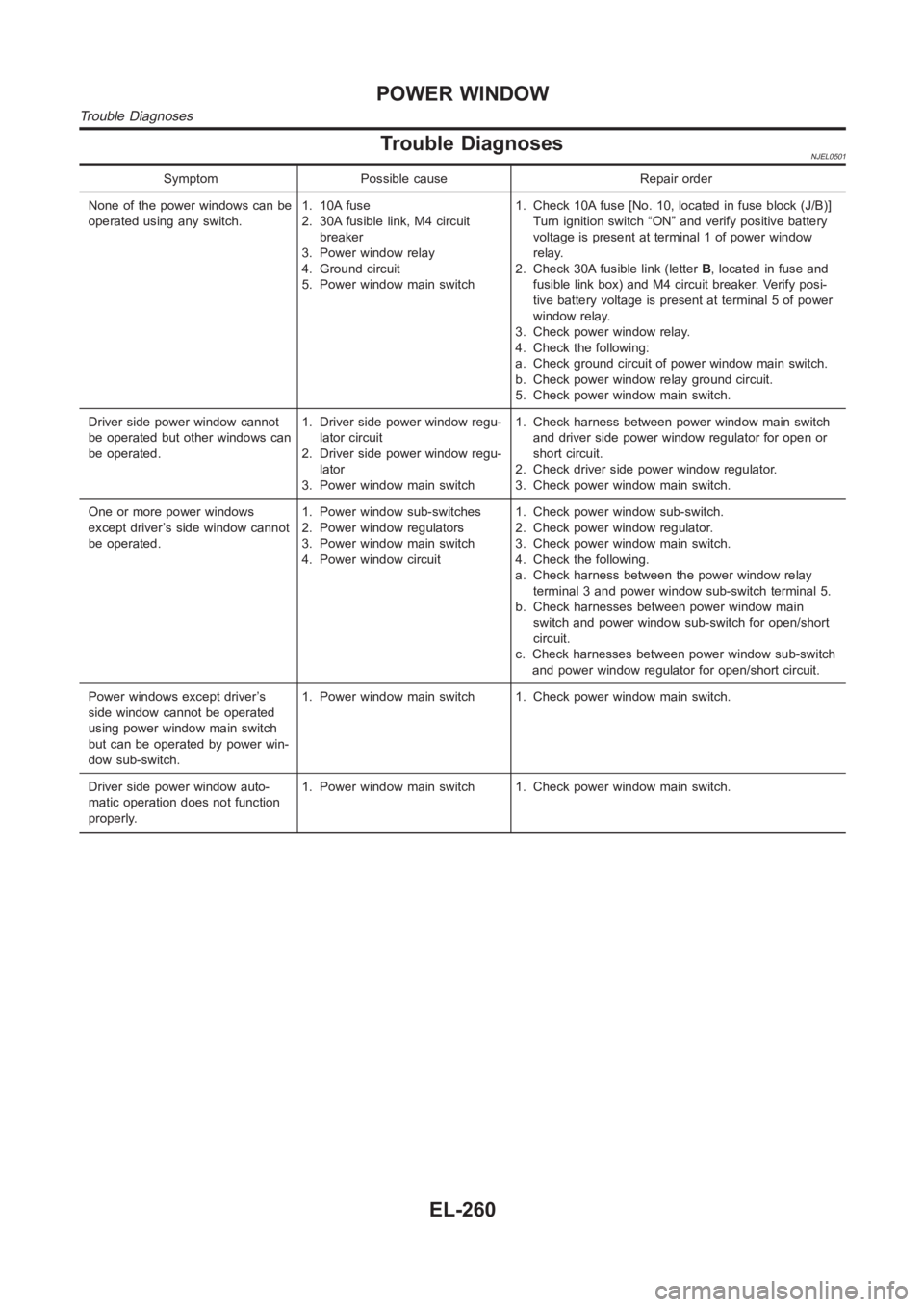
Trouble DiagnosesNJEL0501
Symptom Possible cause Repair order
None of the power windows can be
operated using any switch.1. 10A fuse
2. 30A fusible link, M4 circuit
breaker
3. Power window relay
4. Ground circuit
5. Power window main switch1. Check 10A fuse [No. 10, located in fuse block (J/B)]
Turn ignition switch “ON” and verify positive battery
voltage is present at terminal 1 of power window
relay.
2. Check 30A fusible link (letterB, located in fuse and
fusible link box) and M4 circuit breaker. Verify posi-
tive battery voltage is present at terminal 5 of power
window relay.
3. Check power window relay.
4. Check the following:
a. Check ground circuit of power window main switch.
b. Check power window relay ground circuit.
5. Check power window main switch.
Driver side power window cannot
be operated but other windows can
be operated.1. Driver side power window regu-
lator circuit
2. Driver side power window regu-
lator
3. Power window main switch1. Check harness between power window main switch
and driver side power window regulator for open or
short circuit.
2. Check driver side power window regulator.
3. Check power window main switch.
One or more power windows
except driver’s side window cannot
be operated.1. Power window sub-switches
2. Power window regulators
3. Power window main switch
4. Power window circuit1. Check power window sub-switch.
2. Check power window regulator.
3. Check power window main switch.
4. Check the following.
a. Check harness between the power window relay
terminal 3 and power window sub-switch terminal 5.
b. Check harnesses between power window main
switch and power window sub-switch for open/short
circuit.
c. Check harnesses between power window sub-switch
and power window regulator for open/short circuit.
Power windows except driver’s
side window cannot be operated
using power window main switch
but can be operated by power win-
dow sub-switch.1. Power window main switch 1. Check power window main switch.
Driver side power window auto-
matic operation does not function
properly.1. Power window main switch 1. Check power window main switch.
POWER WINDOW
Trouble Diagnoses
EL-260
Page 2628 of 3189
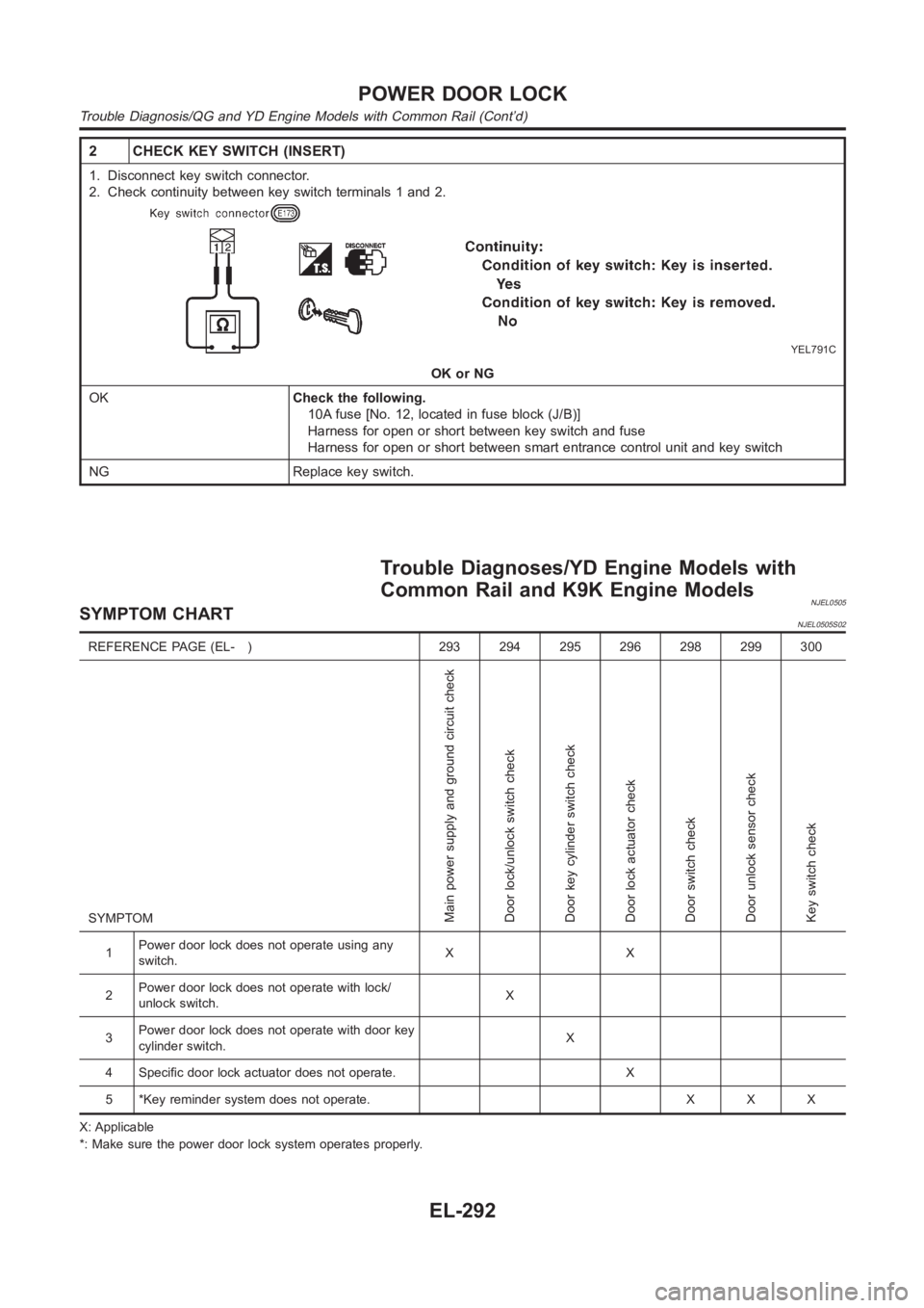
2 CHECK KEY SWITCH (INSERT)
1. Disconnect key switch connector.
2. Check continuity between key switch terminals 1 and 2.
YEL791C
OK or NG
OKCheck the following.
10A fuse [No. 12, located in fuse block (J/B)]
Harness for open or short between key switch and fuse
Harness for open or short between smart entrance control unit and key switch
NG Replace key switch.
Trouble Diagnoses/YD Engine Models with
Common Rail and K9K Engine Models
NJEL0505SYMPTOM CHARTNJEL0505S02
REFERENCE PAGE (EL- ) 293 294 295 296 298 299 300
SYMPTOM
Main power supply and ground circuit check
Door lock/unlock switch check
Door key cylinder switch check
Door lock actuator check
Door switch check
Door unlock sensor check
Key switch check
1Power door lock does not operate using any
switch.XX
2Power door lock does not operate with lock/
unlock switch.X
3Power door lock does not operate with door key
cylinder switch.X
4 Specific door lock actuator does not operate. X
5 *Key reminder system does not operate. X X X
X: Applicable
*: Make sure the power door lock system operates properly.
POWER DOOR LOCK
Trouble Diagnosis/QG and YD Engine Models with Common Rail (Cont’d)
EL-292
Page 2636 of 3189
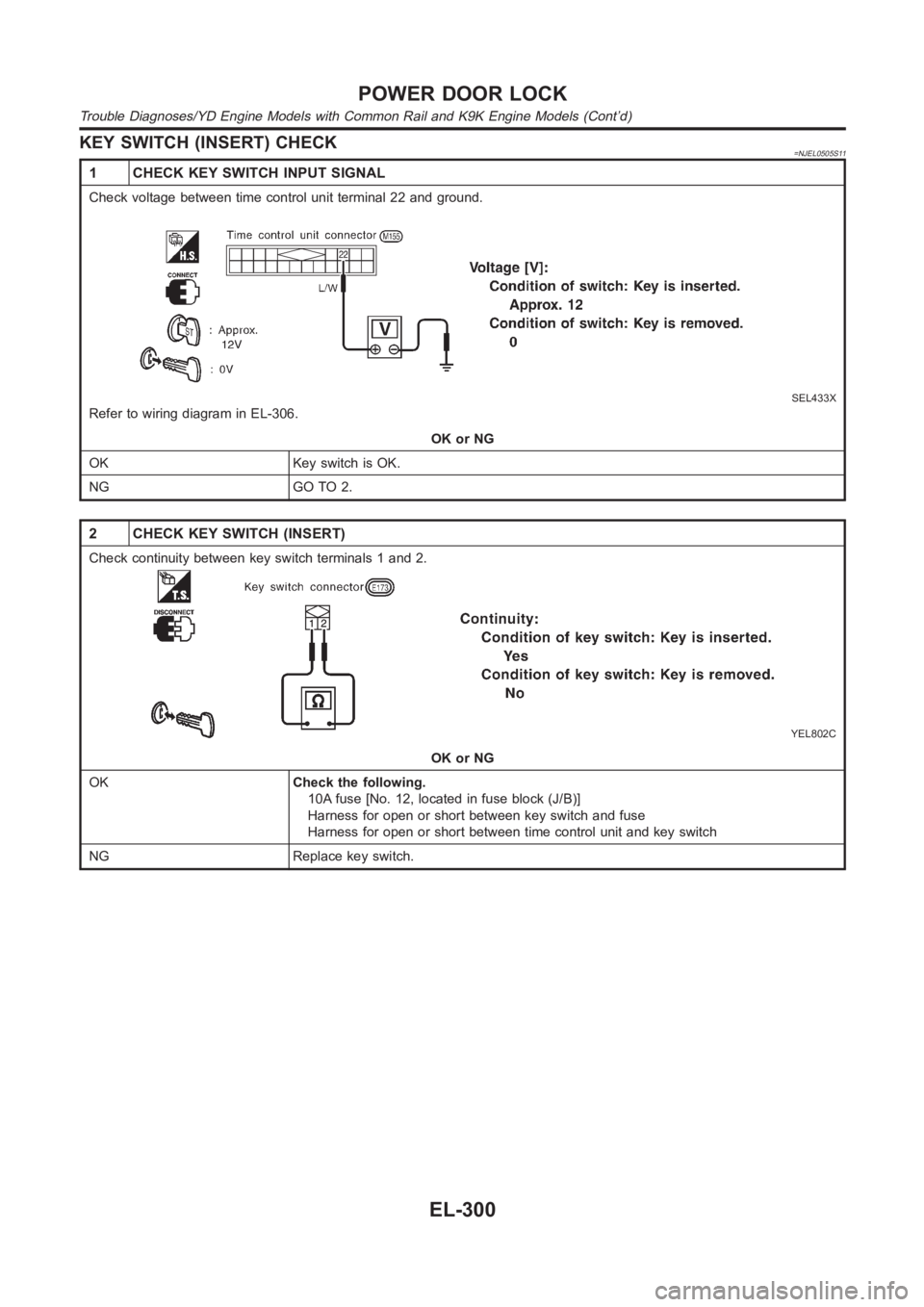
KEY SWITCH (INSERT) CHECK=NJEL0505S11
1 CHECK KEY SWITCH INPUT SIGNAL
Check voltage between time control unit terminal 22 and ground.
SEL433X
Refer to wiring diagram in EL-306.
OK or NG
OK Key switch is OK.
NG GO TO 2.
2 CHECK KEY SWITCH (INSERT)
Check continuity between key switch terminals 1 and 2.
YEL802C
OK or NG
OKCheck the following.
10A fuse [No. 12, located in fuse block (J/B)]
Harness for open or short between key switch and fuse
Harness for open or short between time control unit and key switch
NG Replace key switch.
POWER DOOR LOCK
Trouble Diagnoses/YD Engine Models with Common Rail and K9K Engine Models(Cont’d)
EL-300
Page 2654 of 3189
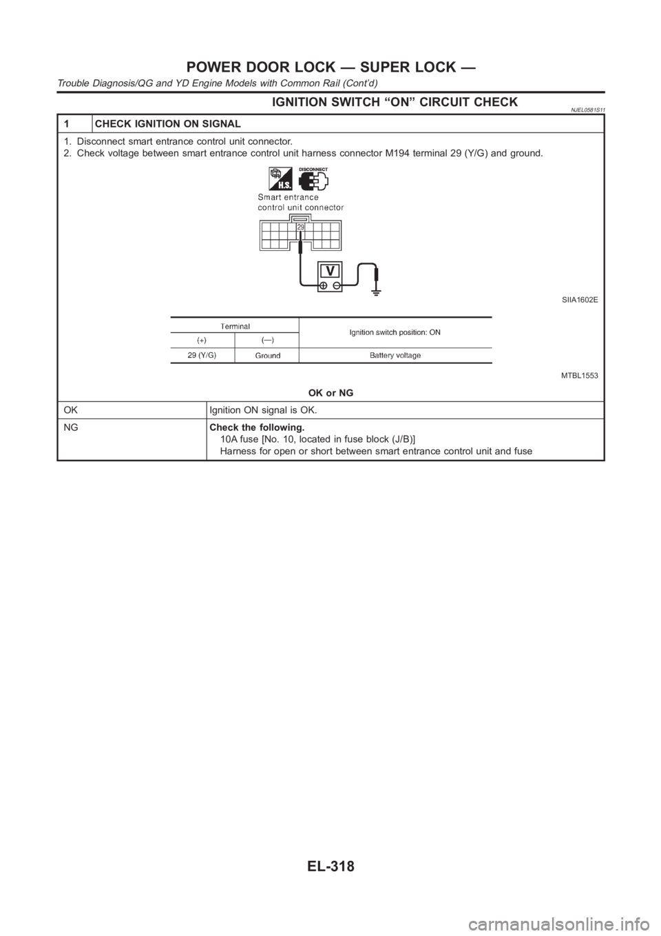
IGNITION SWITCH “ON” CIRCUIT CHECKNJEL0581S11
1 CHECK IGNITION ON SIGNAL
1. Disconnect smart entrance control unit connector.
2. Check voltage between smart entrance control unit harness connector M194 terminal 29 (Y/G) and ground.
SIIA1602E
MTBL1553
OK or NG
OK Ignition ON signal is OK.
NGCheck the following.
10A fuse [No. 10, located in fuse block (J/B)]
Harness for open or short between smart entrance control unit and fuse
POWER DOOR LOCK — SUPER LOCK —
Trouble Diagnosis/QG and YD Engine Models with Common Rail (Cont’d)
EL-318